Directed CHRYSLER4 User manual

CHRYSLER4
INSTALLATION GUIDE
This product is intended for installation by a professional installer only! Attempts to install this
product by a person other than a trained professional may result in severe damage to a vehicle’s
electrical system and components.
2019-05-15
© 2019 Directed, Vista CA
Directed Digital
Solutions
Designed by Installers for Installers

Contents
Warning! Safety first ....................................................................................................................... 3
Introduction .................................................................................................................................... 4
Pre-installation and application warnings ..................................................................................... 4
Vehicle application guide........................................................................................................... 5
Wiring connections ......................................................................................................................... 6
Main power harness (H1), 12-pin thick gauge connector ............................................................... 6
Auxiliary output harness (H2), 16-pin black connector ................................................................... 6
Analog harness (H3), 18-pin white connector ............................................................................... 7
MC501 harness (H4), 8 thick-gauge wires (optional)..................................................................... 7
Installation (wiring diagrams & vehicle wiring reference charts) ............................................................ 8
Type 1 ..................................................................................................................................... 8
Type 2 ................................................................................................................................... 10
Type 3 ................................................................................................................................... 12
Connecting the module .................................................................................................................. 14
Important! .............................................................................................................................. 14
Manual or automatic transmission selection ................................................................................ 14
Optional sensors ..................................................................................................................... 15
RF Systems ............................................................................................................................. 15
When used in conjunction with SmartStart.................................................................................. 15
Module programming.............................................................................................................. 16
LED diagnostics and troubleshooting.......................................................................................... 17
Soft reset................................................................................................................................ 19
Hard reset .............................................................................................................................. 19
Learning the Tach (not needed with Virtual Tach) ............................................................................... 20
Initializing Virtual Tach (not needed with hardwired or data tach applications) ..................................... 20
Limited lifetime consumer warranty .................................................................................................. 21
Quick Reference Guide.................................................................................................................. 22

Warning! Safety first
The following safety warnings must be observed at all times:
• Due to the complexity of this system, installation of this product must only be performed by an authorized Directed dealer.
• When properly installed, this system can start the vehicle via a command signal from the remote control. Therefore, never
operate the system in an area that does not have adequate ventilation.
The following precautions are the sole responsibility of the user; however, authorized Directed dealers should:
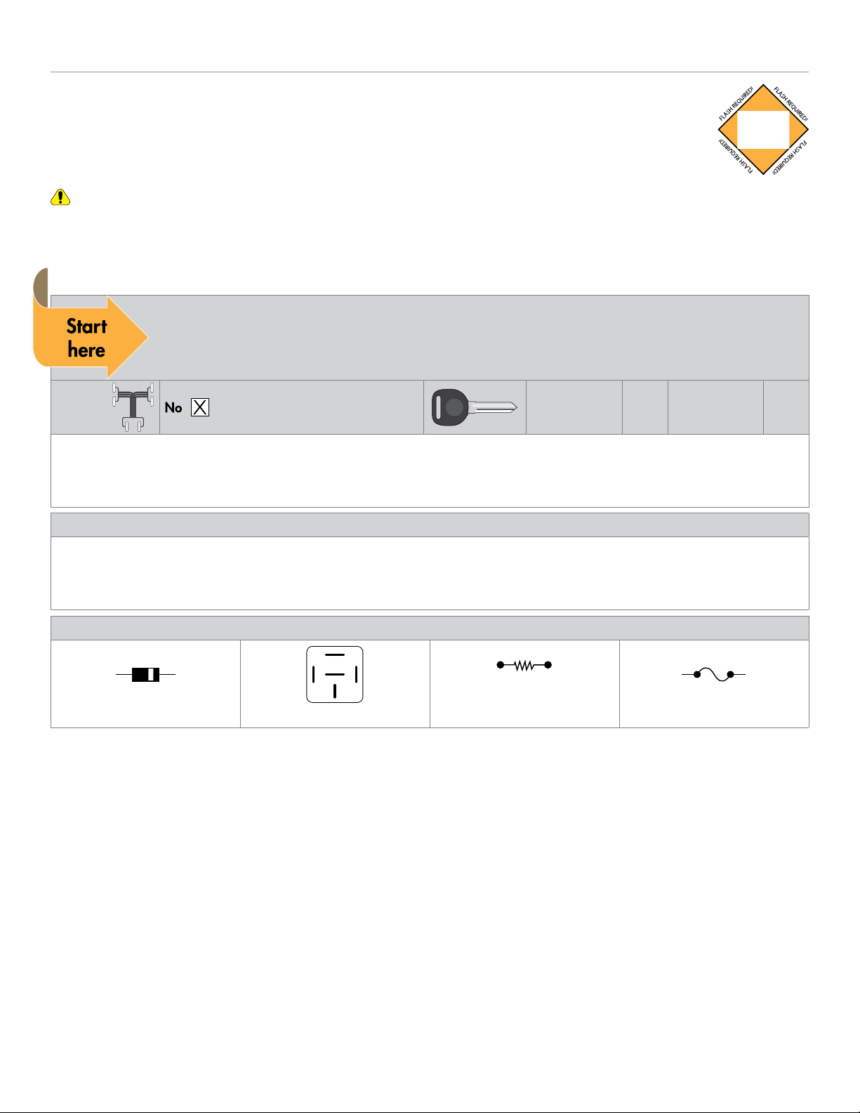
• Never use a test light or logic probe when installing this unit. Always use a multimeter.
• Never operate the system in an enclosed or partially enclosed area without ventilation (such as a garage).
• When parking in an enclosed or partially enclosed area or when having the vehicle serviced, the remote start system must
be disabled using the installed toggle switch. It is the user’s sole responsibility to properly handle and keep out of reach from
children all remote controls to assure that the system does not unintentionally remote start the vehicle.
• USER MUST INSTALL A CARBON MONOXIDE DETECTOR IN OR ABOUT THE LIVING AREA ADJACENT TO THE VEHICLE.
ALL DOORS LEADING FROM ADJACENT LIVING AREAS TO THE ENCLOSED OR PARTIALLY ENCLOSED VEHICLE
STORAGE AREA MUST REMAIN CLOSED AT ALL TIMES.
Use of this product in a manner contrary to its intended mode of operation may result in property damage, personal injury, or
death. Except when performing the Safety Check outlined in this installation guide, (1) Never remotely start the vehicle with
the vehicle in gear, and (2) Never remotely start the vehicle with the keys in the ignition. The user is responsible for having the
neutral safety feature of the vehicle periodically checked, wherein the vehicle must not remotely start while the car is in gear.
This testing should be performed by an authorized Directed dealer in accordance with the Safety Check outlined in this product
installation guide. If the vehicle starts in gear, cease remote start operation immediately and consult with the user to fix the problem
immediately.
OPERATION OF THE REMOTE START MODULE IF THE VEHICLE STARTS IN GEAR IS CONTRARY TO ITS INTENDED MODE OF
OPERATION. OPERATING THE REMOTE START SYSTEM UNDER THESE CONDITIONS MAY RESULT IN PROPERTY DAMAGE
OR PERSONAL INJURY. IMMEDIATELY CEASE THE USE OF THE UNIT AND REPAIR OR DISCONNECT THE INSTALLED REMOTE
START MODULE. DIRECTED WILL NOT BE HELD RESPONSIBLE OR PAY FOR INSTALLATION OR REINSTALLATION COSTS.
Remote starters for manual transmission pose significant risks if not properly installed and operated. When testing to ensure the
installation is working properly, only remote start the vehicle in neutral gear, on a flat surface and with a functional, fully engaged
parking brake. Do not allow anyone to stand in front of or behind the vehicle.
This product should not be installed in any convertible vehicles, soft or hard top with a manual transmission. Installation in such
vehicles may pose certain risk.
3Directed Digital Solutions CHRYSLER4
© 2019-05-15 Directed. All rights reserved.

Introduction
The CHRYSLER4 firmware for Directed Digital Solutions is compatible with specific Chrysler, Dodge/Ram
and Jeep vehicles. It is a complete solution for remote start, security (if applicable), bypass interface, and
convenience. This guide provides information on the installation of the module using CHRYSLER4. If you would
prefer using this system as a digital solution, go to www.directechs.com and search for the make, model and
year of the vehicle. This will allow you to find the proper firmware and corresponding installation guide.
Warning! This module can only be programmed via the web tool, which can be found on www.directechs.com or using the
Directechs Mobile application for mobile devices. Features and functions will become accessible when you connect the module
using the XKLoader.
Pre-installation and application warnings
Firmware notes: This section highlights important information for this specific firmware and will assist in
pricing accordingly, as well as bringing awareness to any operational or vehicle limitations.
T-Harness
compatible
Keys required for
programming 1Keys required for
operation 0
Unless specified otherwise, all connectors are displayed from the wire side, with the exception of the OBDII diagnostic
connector.
Refer to the "Vehicle wiring reference chart" following each installation type.
General notes: This section highlights important information for this specific firmware.
[1] The installation of an aftermarket hood pin is ONLY required on vehicles that are NOT equipped with a factory hood pin.
[2] The siren is ONLY required when enabling the security features during module flashing.
[3] The Green wire is ONLY required for starter disable and antigrind applications.
Additional parts required (maximum required):
Diode 6A
0 x 1A Diodes 86 85
30
87a
87
1 x Relay
Resistor 100Ω
1 x Resistor
2100 or 1K or 910 Ω
Fuse 7.5A
0 x Fuse
4Directed Digital Solutions CHRYSLER4
© 2019-05-15 Directed. All rights reserved.

Vehicle application guide
The following table lists the vehicles and features which are compatible with this product. The number assigned to each year
allows you to determine which installation type should be used for your vehicle.
Vehicles
2008
2007
2006
2005
2004
PK-Immobilizer Bypass-Data No Key Req'd
DL-Arm Factory Security
DL-Disarm Factory Security
DL-Door Lock Control
DL-Door Unlock
DL-Driver Priority Unlock
DL-Sliding Door Control Driver
DL-Sliding Door Control Passenger
DL-Trunk / Hatch Release
FOB-Control of aftermarket alarm with OEM remote
RS-3x LOCK START (Start control using OEM Remote)
RS-3x LOCK STOP (Stop control using OEM Remote)
RS-SmartStart
RS-Tach / RPM Output
SS-Entry Monitoring ALL Door Pins
SS-Entry Monitoring Trunk/Hatch Pin
ST-Brake Status (foot brake)
ST-Ignition Status
Chrysler
Pacifica 22222
•••••• ••••••••••
Town & Country 1111
••••••••••••••••••
Dodge/Ram
Caravan 1111
••••••••••••••••••
Grand Caravan 1111
••••••••••••••••••
Jeep
Liberty 3 3 3
•••••• •••••••••
Le
g
end:
DL: OE Door Lock & Alarm Controls
FOB: S
y
nc CAN Interface w/ FOB Remote
PK: Trans
p
onder & Immobilizer Override
RS: Remote Start & En
g
ine Controls
SS: Inte
g
rated Securit
y
& Monitorin
g
ST: Function/Feature Status
5Directed Digital Solutions CHRYSLER4
© 2019-05-15 Directed. All rights reserved.

Wiring connections
The wiring connections listed below are specific to this firmware.
Main power harness (H1), 12-pin thick gauge connector
Conn./Pin Color Description
H1/1 White Relay 3 COM – (+) Parking Light Output 1
H1/2 White/Brown Relay 3 N.O.– (+) 2V Input 1
H1/3 Brown/Red Relay 2 N.O (+) 12V Input
H1/4 Yellow/Red Relay 2 COM – (+) Starter Ouput
H1/5 Orange/Red Relay 2 N.C. – No Connection
H1/6 Yellow Relay 1 COM – (+) Ignition Interrupt (conn. side) 1
H1/7 White Relay 3 COM – (+) Parking Light Output 1
H1/8 White/Brown Relay 3 N.O.– (+) 12V Input 1
H1/9 Black (-) Ground
H1/10 Red (+) 12 Volt (Battery)
H1/11 Orange/Yellow Relay 1 N.C. – (+) Ignition Interrupt (vehicle side) 1
H1/12 Brown Relay 1 N.O.– No Connection 1
Auxiliary output harness (H2), 16-pin black connector
Conn./Pin Color Description
H2/1 Violet/Brown MUX Starter/Ignition Output or MUX Parking Light Output
H2/2 Yellow/Black No Connection
H2/3 Orange/Black No Connection
H2/4 Tan No Connection
H2/5 Tan/Black No Connection
H2/6 Light Green No Connection
H2/7 Orange/Green No Connection
H2/8 Orange/Brown No Connection
H2/9 Violet/Green MUX Starter/Ignition Input
H2/10 Green/Black (-) RAP Off Output 2
H2/11 White/Violet No Connection 2
H2/12 White/Red (+) Ignition Output 2
H2/13 Lt. Blue/Black No Connection 2
H2/14 Green/Red No Connection 2
H2/15 N/A No Connection
H2/16 Violet/Yellow J1850
1. If these outputs are not used by the firmware, they can be configured by the installer when the module is flashed.
2. If these outputs are not used by the firmware, they can be configured by the installer when the module is flashed. Note that they are low current and a relay
may be necessary.
6Directed Digital Solutions CHRYSLER4
© 2019-05-15 Directed. All rights reserved.

Analog harness (H3), 18-pin white connector
Conn./Pin Color Description
H3/1 Lt. Blue/Red No Connection
H3/2 Black/White (-) Parking Brake Input (Manual Transmission) 2
H3/3 Gray (-) Hood Input 2
H3/4 N/A No Connection
H3/5 Gray/Black (+) Glow Plug Input 2
H3/6 Violet/White (AC) Tach Input 2
H3/7 Dark Blue No Connection 1
H3/8 Brown/Black No Connection 1
H3/9 Red/White No Connection 1
H3/10 White/Green (-) Door Input 2
H3/11 Yellow/Green (+) Door Input 2
H3/12 Blue/Red No Connection
H3/13 Light Blue (-) Trunk Trigger Input 2
H3/14 Pink/Yellow No Connection 1
H3/15 Dark Green No Connection 1
H3/16 Brown/White (+) Brake Input 2
H3/17 Brown (+) Siren Output 1
H3/18 Blue/White No Connection 1
MC501 harness (H4), 8 thick-gauge wires (optional)
Conn./Pin Color Description
H4/1 Pink/White (+) Ignition 2/Flex Relay Output 3
H4/2 Red/White (+) Fused (30A) Ignition 2/Flex Relay Input
H4/3 Pink (+) Ignition Output (also input to Yellow in ribbon cable)
H4/4 Red (+) 12 Volt (battery) Input
H4/5 Orange (+) Accessory Output
H4/6 Red (+) 12 Volt (battery) Input
H4/7 Green Starter Input (from key switch) 4
H4/8 Violet (+) Starter Output (to starter)
1. If these outputs are not used by the firmware, they can be configured by the installer when the module is flashed. Note that they are low current and a relay
may be necessary.
2. These connections are only required if the corresponding statuses are not supported by the firmware. See "Vehicle application guide" on page 5 for a
list of compatible features.
3. If these outputs are not used by the firmware, they can be configured by the installer when the module is flashed.
4. The Green wire is only required for starter disable and anti-grind applications.
7Directed Digital Solutions CHRYSLER4
© 2019-05-15 Directed. All rights reserved.

Installation (wiring diagrams & vehicle wiring reference charts)
Type 1
Refer to "Pre-installation and application warnings" on page 4 for important information, such as the description of special notes referenced in the diagram ( ).
Refer to "Pre-installation and application warnings" for important information, such as the description of each special note referenced in the diagram ( ).
4: Yellow/Red: (+) Start Output
(+) Ignition Output: White/Red: 12
(-) RAP Off Output: Green/Black: 10
9: Black: (-) Ground
10: Red: (+) 12V Input
(-) Hood Input: Gray: 3
Hood pin
(MUX) Starter/Ignition Input: Violet/Green: 9
(MUX) Starter/Ignition Output: Violet/Brown: 1
J1850: Violet/Yellow: 16
3: Brown/Red: (+) 12V Input
6: Yellow: Ignition Interrupt (conn. side)
11: Orange/Yellow: Ignition Interrupt (veh. side)
SKIM (Sentry Key Immobilizer Module)
(black conn. at ignition switch)
J1850:
White/Violet,
pin 2
Immo. Ignition:
Pink/White or Pink/Gray,
pin 4
(MUX) Starter/Ignition:
Violet /Brown, pin 2
(+) Start:
Yellow, pin 4
(+) Ignition:
Pink/White or
Pink/Gray, pin 3
Ignition
Switch
(Connector
Side View)
Module-Sentry Key
Ignition Switch
Ignition
Cylinder
The Remote Start
Safety Override
Switch MUST be in
the ON position.
Remote Start Safety
Override Switch
2 & 8: White/Brown: (+) 12V Input
1 & 7: White: (+) Parking Light Output
(+) Siren Output: Brown: 17
Siren
(-) Driver’s Door Trigger: Violet, pin 6
126
34 9
BCM
(Black conn. third
down from top)
BCM Power Connector
(Black top conn. at BCM)
(+) 12V: Violet/Red, pin 5
5
Cut
86 85
30
87a
87
(MUX) Parking Light:
White/Brown, pin 11
1
6
13 7
Headlight Switch
(black conn.
headlight switch)
Cut
Resistor 2100Ω
8Directed Digital Solutions CHRYSLER4
© 2019-05-15 Directed. All rights reserved.

Vehicle wiring reference chart
This section provides vehicle wiring information to guide you through the various stages of your installation. Refer to
www.directechs.com for additional information.
Wire Information Connector Information
Function Color Pin Polarity Location Color Pins Ref.
Chrysler Town & Country 2004-2007
Starter Yellow 4 (+) Ignition switch. Black 5 A
Ignition Pink/White 3 (+) Ignition switch. Black 5 A
MUX Starter/Ignition Violet/Brown 2 MUX Ignition switch. Black 5 A
12V Violet/Red 5 (+) Top connector on BCM. Black 6 B
J1850 White/Violet 2 Data SKIM (Sentry Key Immobilizer Module) Black 6 C
Immo. Ignition Pink/White or Pink/Gray 4 Cut SKIM (Sentry Key Immobilizer Module) Black 6 C
Parking Lights White/Brown or White/
Orange N/A (+) Drivers kick panel. N/A N/A D
Driver Door Trigger Violet 6 (-) Third connector from top of BCM. Black 34 E
Dodge Caravan 2004-2007
Starter Yellow 4 (+) Ignition switch. Black 5 A
Ignition Pink/White 3 (+) Ignition switch. Black 5 A
MUX Starter/Ignition Violet/Brown 2 MUX Ignition switch. Black 5 A
12V Violet/Red 5 (+) Top connector on BCM. Black 6 B
J1850 White/Violet 2 Data SKIM (Sentry Key Immobilizer Module) Black 6 C
Immo. Ignition Pink/White 4 Cut SKIM (Sentry Key Immobilizer Module) Black 6 C
Parking Lights White/Orange N/A (+) Drivers kick panel. N/A N/A D
Driver Door Trigger Violet 6 (-) Third connector from top of BCM. Black 34 E
Dodge Grand Caravan 2004-2007
Starter Yellow 4 (+) Ignition switch. Black 5 A
Ignition Pink/White or Pink/Gray 3 (+) Ignition switch. Black 5 A
MUX Starter/Ignition Violet/Brown 2 MUX Ignition switch. Black 5 A
12V Violet/Red 5 (+) Top connector on BCM. Black 6 B
J1850 White/Violet 2 Data SKIM (Sentry Key Immobilizer Module) Black 6 C
Immo. Ignition Pink/White 4 Cut SKIM (Sentry Key Immobilizer Module) Black 6 C
Parking Lights White/Orange N/A (+) Drivers kick panel. N/A N/A D
Driver Door Trigger Violet 6 (-) Third connector from top of BCM. Black 34 E
9Directed Digital Solutions CHRYSLER4
© 2019-05-15 Directed. All rights reserved.

Type 2
Refer to "Pre-installation and application warnings" on page 4 for important information, such as the description of special notes referenced in the diagram ( ).
4: Yellow/Red: (+) Start Output
(+) Ignition Output: White/Red: 12
(-) RAP Off Output: Green/Black: 10
9: Black: (-) Ground
10: Red: (+) 12V Input
(-) Hood Input: Gray: 3
Hood pin
(MUX) Starter/Ignition Input: Violet/Green: 9
(MUX) Starter/Ignition Output: Violet/Brown: 1
J1850: Violet/Yellow: 16
3: Brown/Red: (+) 12V Input
6: Yellow: Ignition Interrupt (conn. side)
11: Orange/Yellow: Ignition Interrupt (veh. side)
SKIM (Sentry Key Immobilizer Module)
(black conn. at ignition switch)
J1850:
White/Violet,
pin 2
Immo. Ignition:
Pink/White or Pink/Gray,
pin 4
(MUX) Starter/Ignition:
Violet /Brown, pin 2
(+) Start:
Yellow, pin 4
(+) Ignition: Pink/Blue
or Pink/Gray, pin 3
Ignition
Switch
(Connector
Side View)
Module-Sentry Key
Ignition Switch
Ignition
Cylinder
The Remote Start
Safety Override
Switch MUST be in
the ON position.
Remote Start Safety
Override Switch
2 & 8: White/Brown: (+) 12V Input
1 & 7: White: (+) Parking Light Output
(+) Siren Output: Brown: 17
Siren
BCM Power Connector
(Black top conn. at BCM)
(+) 12V: Violet/Red, pin 5
5
(-) Driver’s Door Trigger:
Violet, pin 11
1
11
20
10
Drivers Door Module
(Black conn. in driver’s door)
Headlight switch
(Black conn. at headlights)
1
7
2
8
3
9
4
10
5
11
6
12
30
86 85
87
87a
Cut
Resistor 1K Ω
MUX Parking
Lights: Brown/White, pin 6
Cut
10 Directed Digital Solutions CHRYSLER4
© 2019-05-15 Directed. All rights reserved.

Vehicle wiring reference chart
This section provides vehicle wiring information to guide you through the various stages of your installation. Refer to
www.directechs.com for additional information.
Wire Information Connector Information
Function Color Pin Polarity Location Color Pins Ref.
Chrysler Pacifica 2004-2008
Starter Yellow 4 (+) Ignition switch. Black 5 A
Ignition Pink/Blue or Pink/Gray 3 (+) Ignition switch. Black 5 A
MUX Starter/Ignition Violet/Brown 2 MUX Ignition switch. Black 5 A
12V Violet/Red 5 (+) Top connector on BCM. Black 6 B
J1850 White/Violet 2 Data SKIM (Sentry Key Immobilizer Module) Black 6 C
Immo. Ignition Pink/White or Pink/Gray 4 Cut SKIM (Sentry Key Immobilizer Module) Black 6 C
Parking Lights Brown/White 6 MUX Headlight switch. Black 12 D
Driver Door Trigger Violet 11 (-) Drivers Door Module Black 20 E
11 Directed Digital Solutions CHRYSLER4
© 2019-05-15 Directed. All rights reserved.

Type 3
Refer to "Pre-installation and application warnings" on page 4 for important information, such as the description of special notes referenced in the diagram ( ).
9: Black: (-) Ground
10: Red: (+) 12V Input (+) 12V
Hood Pin
(-) Hood Input: Gray: 3
(-) RAP Off Output: Green/Black: 10
J1850: Violet/Yellow: 16
6: Yellow: Ignition Interrupt (connector side)
11: Orange/Yellow: Ignition Interrupt (vehicle side)
SKIM (Sentry Key Immobilizer Module)
(black connector at ignition switch)
J1850:
White/Violet,
pin 2
Immo. Ignition:
Pink/Lt. Green or
White/Violet, pin 4
(+) 12V:
Red,pin 1
Ignition Switch
BCM
(black top connector on BCM)
2 & 8: White/Brown: (+) 12V Input (+) 12V
Module-Sentry Key
Ignition Switch
Ignition
Cylinder
10
5
9
4
8
3
7
2
6
1
(+) Accessory 2/Flex Relay
Output: Pink/White
(+) Ignition Output (also input
to Yellow wire in ribbon
cable): Pink
(+) 12V Input: Red
(+) Accessory Output: Orange
(+) 12V Input: Red
Starter Input (from
key switch): Green
(+) Starter Output
(to starter): Violet
(+) Fused (30A) Accessory 2/
Flex Relay Input: Red/White
(+) Start:
Lt. Blue/Red, pin 6
(+) Accessory 2:
Pink/Yellow, pin 7
(+) Accessory 1:
Pink/Yellow, pin 8
(+) Ignition:
Pink/Lt. Green,pin 2
The Remote Start
Safety Override
Switch MUST be in
the ON position.
Remote Start Safety
Override Switch
(+) Siren Output: Brown: 17
Siren
(MUX) Parking Lights:
Pink/Red, pin 5
BCM
(gray bottom
connector at BCM)
1213
12
22
11 3
14
4
15
5
16
6
17
7
18
8
19
9
20
10
21
7 White4 White
8 thick-gauge wires
MC501
(-) Drivers Door
Trigger:
Violet, pin 4
1326
14 1
Cut
1 & 7: White: (+) Parking Light Output
30
86 85
87
87a
Cut
Resistor 910 Ω
12 Directed Digital Solutions CHRYSLER4
© 2019-05-15 Directed. All rights reserved.

Vehicle wiring reference chart
This section provides vehicle wiring information to guide you through the various stages of your installation. Refer to
www.directechs.com for additional information.
Wire Information Connector Information
Function Color Pin Polarity Location Color Pins Ref.
Jeep Liberty 2005-2007
12V Red 1 (+) Ignition switch. Black 10 A
Starter Lt. Blue/Red 6 (+) Ignition switch. Black 10 A
Ignition Pink/Lt. Green 2 (+) Ignition switch. Black 10 A
Accessory 1 Pink/Yellow 7 (+) Ignition switch. Black 10 A
Accessory 2 Pink/Yellow 8 (+) Ignition switch. Black 10 A
J1850 White/Violet 2 Data SKIM (Sentry Key Immobilizer Module) Black 6 B
Immo. Ignition Pink/Lt. Green or White/
Violet 4 Cut SKIM (Sentry Key Immobilizer Module) Black 6 B
Parking Lights Pink/Red 5 MUX Bottom connector on BCM Gray 22 C
Driver Door Trigger Violet 4 (-) Top connector on BCM Gray 26 D
13 Directed Digital Solutions CHRYSLER4
© 2019-05-15 Directed. All rights reserved.

Connecting the module
Important!
Before connecting the Directed Digital Solutions, it is important to ensure that the proper feature and function programming is
selected using the configuration wizard. Visit www.directechs.com to use the latest version of the online tool.
Flashing a module using your computer:
1. Disconnect the main module from any (+) 12V power source, then connect it to your computer using the XKLoader2.
2. Go to www.directechs.com using Internet Explorer; the configuration wizard will be displayed automatically.
3. Follow the instructions in the pop up window that will be displayed when the module is detected.
Flashing a module using your smartphone or tablet:
1. Disconnect the main module from any (+) 12V power source, then connect it to the XKLoader3.
2. Launch the Directechs Mobile app on your smartphone or tablet.
3. Select FLASH YOUR MODULE and follow the on-screen instructions.
When the flashing operation is successful, you can proceed with the instructions below.
Manual or automatic transmission selection
The yellow loop on the Directed Digital Solutions controls which transmission type the unit is configured for. The state of the loop
(uncut or cut) when the main module is powered up will determine which type is selected.
• Uncut (default): Manual transmission.
• Cut: Automatic transmission.
For safety reasons, all Directed Digital Solutions are shipped ready to use with a manual transmission (the yellow loop is
untouched). If the loop is cut after power has been applied, it is necessary to cycle power to the main module (via the white 12-
pin main power harness) so the unit will see the state change on the loop and appropriately configure the transmission type.
Ready mode
To successfully remote start a vehicle equipped with a manual transmission, the Ready Mode feature must be enabled before
exiting the vehicle. Please refer to the Owner’s Guide for more details on this required process.
Additional connections required for vehicles equipped with a manual transmission (if not supported by firmware)
Connection Description
(-) E-Brake Status Input
(Black/White, pin 2)
Must be connected to a working emergency brake in the vehicle. Although most vehicles have simple
(-) trigger emergency brake circuits note some vehicles do not and may require unique integration
methodologies.
(-) Door Trigger Input
(White/Green, pin 10)
OR (+) Door Input (Yellow/
Green, pin 11)
Must be connected to a working door trigger in the vehicle, which monitors all doors. The unit must monitor
the door pins to allow the Ready Mode process to be enabled.
Note: Some vehicles may require unique integration methodologies for this circuit. For more information, refer
to www.directechs.com.
(AC) Tachometer Input
(Violet/White, pin 6)
Must be connected to a working tachometer signal in the vehicle (fuel injector, ignition coil, true tach, etc.)
and learned successfully to the Directed Digital Solutions.
14 Directed Digital Solutions CHRYSLER4
© 2019-05-15 Directed. All rights reserved.

Optional sensors
Note: The sensor port is only active on hybrid systems.
The 4-pin sensor port is compatible with a number of different Directed sensors including, but not limited to:
• Shock Sensor – 504D
• Field Disturbance Sensor – 508D
• Ultrasonic Sensor – 509U
Note: In the case of 508D, power and ground must be hardwired to the vehicle – power and ground should NOT be obtained
from the 4-pin sensor port.
Each sensor will have its own instructions, which must be followed for installation and adjustment.
RF Systems
An RF System consists of one or multiple remotes, a Control Center (antenna), and an antenna cable – various combinations exist.
An RF System allows the vehicle owner to control the system with enhanced range. Two-way models are available. Please follow
the instructions included with the kit for appropriate installation and programming information.
When flashing the Directed Digital Solutions, make sure to pick the remote you will be using. This way the main module will have
the necessary firmware to interact with the remote and Control Center (antenna) combination.
When used in conjunction with SmartStart
Disconnect power from the Directed Digital Solutions before connecting the SmartStart module. Failing to do so could damage
main module. To enable D2D communication between the Directed Digital Solutions and the SmartStart one of the following
actions must be executed:
• SmartStart with Loops – The brown loop must be cut.
• SmartStart with Pigtails – The gray wire must be connected to a ground source.
Loops Pigtails
DO NOT connect the SmartStart 2-pin power harness when using the Directed Digital Solutions. Power and ground will be
provided by the D2D connector on main module. Refer to the SmartStart documentation for further details.
15 Directed Digital Solutions CHRYSLER4
© 2019-05-15 Directed. All rights reserved.

Module programming
Refer to "LED diagnostics and troubleshooting" on page 17 for more information and for troubleshooting purposes.
To connect the module:
1
Please ensure that the vehicle is in a safe location and cannot move forward during
programming. For vehicles equipped with a manual transmission, make sure the gearshift
lever is in the neutral position.
2Connect all the harnesses to the Directed Digital Solutions, EXCEPT the 12-pin main power
harness.
Connect all but the
12-pin harness
3Connect the 12-pin main power harness, and wait until the LED turns ON solid red.
Must be connected LAST
&Solid
4Insert the key in the ignition without turning it ON, wait for the LED to flash orange. Flash
&
START
Key OUT
ON
OFF
START
Key IN
ON
OFF
START
Key IN
ON
OFF
START
Key IN
ON
OFF
5Turn the key to the ON position. The LED will continue to flash orange. It will
then turn ON solid green or orange for 3 seconds before turning OFF. Continue to
flash Solid Solid
&OR
&
START
Key OUT
ON
OFF
START
Key IN
ON
OFF
START
Key IN
ON
OFF
START
Key IN
ON
OFF
6When green LED turns OFF, turn the ignition OFF and remove the key from the ignition.
The module is successfully programmed. Off &
START
Key OUT
ON
OFF
START
Key IN
ON
OFF
START
Key IN
ON
OFF
START
Key IN
ON
OFF
7
Pair remotes (if applicable). For information on how to pair a specific remote, please
refer to its corresponding owner documentation, which can be found inside the product
packaging of the complete system or on www.directechs.com.*
Pair
remotes*
8
DATA Tach: Firmware using DATA Tach, the tachometer is preprogrammed for the
vehicle and no further action is required. For instructions on how to adjust tach or use
Virtual tach, see page 20 (not needed with hardwired or data tach applications).
Hardwire Tach: Firmware using the Violet/White Hardwire Tach input will require
programming. For instructions on how to program or adjust tach or use Virtual tach, see
page 20 (not needed with hardwired or data tach applications).
Initialize
tachometer
* Your aftermarket remote may differ from the model shown in the illustrations.
You have successfully completed the module programming sequence.
16 Directed Digital Solutions CHRYSLER4
© 2019-05-15 Directed. All rights reserved.

LED diagnostics and troubleshooting
This section provides LED diagnostics and troubleshooting information to guide you through the various stages of your installation.
Module programming
LED Description Troubleshooting
Off Module has no power. Make sure the D2D harness is connected and that 12 Volt is present between the red and black
wires. If 12 Volt is present, the module may be defective.
Solid red
Waiting to begin the programming
sequence. Ensure the correct programming procedure is being followed.
Flashes red &
green
Initialization failed. Reset the module and complete the programming again. If the issue persists, please contact
Technical Support.
Solid orange Transponder functions were skipped. (If compatible) when the RXT mode is not desired or convenience features are needed, please
reset and reprogram the module.
Flashes green
All required CAN networks has been
detected. Normal operation.
Flashes orange 1 of 2 CAN networks has been detected. Normal operation.
Flashes orange
slowly
Key2GO initiated. Please follow the steps indicated in "Module programming" on page 16 to complete the
Key2GO programming.
Solid green x
3 secs
Module was successfully programmed
with all functions. Normal operation.
Solid orange x
3 secs
Module was successfully
programmed without transponder
functions.
Normal operation.
Module programming – Error codes
LED Description Troubleshooting
Flashes red x 1 CAN2 not detected.
Check the CAN2 Orange/Green and Orange/Brown wire connections. Wake up the data bus
by turning the ignition on and try again. If your installation does not require this connection, skip
this step by pressing the programming button 5 times.
Flashes red x 1 J1850 not detected. Check the J1850 wire connection. Wake up the data bus by turning the ignition on and try
again.
Flashes red x 2 CAN1 not detected.
Check the CAN1 Tan and Tan/Black wire connections. Wake up the data bus by turning the
ignition on and try again. If your installation does not require this connection, skip this step by
pressing the programming button 5 times.
Flashes red x 3 Bypass data not detected. Check the bypass line connection. If more than one wire is used, make sure they are not inverted.
Ensure the vehicle still operates correctly using the factory key.
Flashes red x 4 Bypass processing error. The bypass calculation failed. Reset the module and try again. If the condition persists, please
contact Technical Support.
Flashes red x 5 ISO 1 not detected. The Yellow/Black wire did not detect the expected signal. Refer to "Installation (wiring diagrams &
vehicle wiring reference charts)" on page 8 to check the connections.
Flashes red x 6 ISO 2 not detected. The Orange/Black wire did not detect the expected signal. Refer to "Installation (wiring diagrams
& vehicle wiring reference charts)" on page 8 to check the connections.
Flashes red x 7 MUX not detected.
The Violet/Green or Violet/Brown wire did not detect the expected voltage value. Refer to
"Installation (wiring diagrams & vehicle wiring reference charts)" on page 8 to check the
connections.
External module synchronization
LED Description Troubleshooting
(Flashes red, red,
then orange) x 10
OBDII feature not supported. The diagnostic data bus was not detected, therefore the SmartStart features will be limited.
17 Directed Digital Solutions CHRYSLER4
© 2019-05-15 Directed. All rights reserved.

Active Ground When Running (Status)
LED Description Troubleshooting
Flashes green
Ground When Running (Status) command
received. The module has initialized the remote start sequence.
Flashes red &
orange
Ignition ON command received. The module has received the Ignition ON command and is processing the remote start sequence.
Flashes green
quickly
Start ON command received. The module has received the Start ON command and is processing the remote start sequence.
Flashes red x 10 PTS shutdown error. The PTS output from the module was not activated due to safety protection.
Flashes red x 21 CAN bus incorrectly detected. Verify the CAN1 and CAN2 connections. Refer to "Installation (wiring diagrams & vehicle wiring
reference charts)" on page 8 to check the connections.
Commands
LED Description Troubleshooting
Flashes orange x 1 LOCK command received.
If the bypass module fails to flash, it did not receive the signal.
Commands can come from RF or D2D.
Flashes orange x 2 UNLOCK command received.
Flashes orange x 3 TRUNK command received.
Flashes orange x 4 AUX1 command received.
Flashes orange x 5 AUX2 command received.
Flashes orange x 6 AUX3 command received.
Shutdown codes
LED Description Troubleshooting
Flashes green x 1 Takeover successful. Normal operation.
Flashes red x 1 Runsafe was not disabled. No UNLOCK command was received prior to opening the door, or the 45 second timer expired
in takeover mode.
Flashes red x 2 Brake was not detected. The brakes were not detected, which prevents the system from shutting down the vehicle.
Flashes red x 3 Smart key was not detected. The smart key was not detected, which prevents the system from shutting down the vehicle.
Flashes red x 4 Speed was detected. The vehicle was detected as moving, which prevents the system from shutting it down.
Analog error codes
LED Description Troubleshooting
Flashes red, green
& orange
DEI feature error. A feature config file mismatch was detected. Please contact Technical Support.
18 Directed Digital Solutions CHRYSLER4
© 2019-05-15 Directed. All rights reserved.

Soft reset
A module reset will only erase the steps performed in "Module programming" on page 16. The firmware and settings flashed to
the module will not be affected.
1
If required for your installation, connect all the harnesses to the Directed Digital Solutions,
EXCEPT the 12-pin main power harness. Press and hold the programming button, then
connect the 12-pin harness to the module.
Connect all but the
12-pin harness
2Wait 3 seconds until the LED turns ON solid orange then release the programming button.
The LED turns ON solid red. &&
ReleaseSolid Solid
Hard reset
Warning Against Executing a Hard Reset!
A hard reset will revert the flashed firmware back to its default settings. Depending on the installation, some settings may need to
be reconfigured. Connect your module to a computer and use the web configuration tool to edit its programmable features.
1
If required for your installation, connect all the harnesses to the Directed Digital Solutions,
EXCEPT the 12-pin main power harness. Press and hold the programming button, then
connect the 12-pin harness to the module.
Connect all but the
12-pin harness
2After 3 seconds the LED turns ON solid orange. Keep holding the programming button until
the LED flashes red, then orange slowly. HoldSolid Flashes
&&
3Release the programming button. The LED turns ON solid red.
Release
&
Solid
19 Directed Digital Solutions CHRYSLER4
© 2019-05-15 Directed. All rights reserved.

Learning the Tach (not needed with Virtual Tach)
Tach comes preprogrammed, therefore learning is not required; however, it can be readjusted with the following operations:
1. Start the vehicle using the key.
2. Within 5 seconds, press and hold the Control Center (antenna) or the main module programming button, until the LED on the
Control Center (antenna) or the main module turns ON solid.
3. Release the button. The tachometer value is now stored in memory.
If the LED does not turn ON solid, find an alternate tach source.
Note: When the tachometer is programmed, the main module automatically enters the Tachometer engine checking mode.
Initializing Virtual Tach (not needed with hardwired or data tach applications)
To program Virtual Tach:
1. After the install is complete, remote start the engine. The programming operation may require 3 cranks of the starter before
the engine starts and runs. Do not turn off the remote start if this happens, it is a normal programming operation.
2. Once the engine begins running, let it run for at least 30 seconds.
3. Using the Remote, send the Remote start command to turn remote start off. Virtual Tach is programmed. To reset Virtual Tach, a
module reset must be done.
Note: Virtual Tach cannot be used in Manual Transmission Mode. It is also not recommended for diesel trucks.
Virtual Tach handles disengaging the starter motor during remote starting – it does not address over-rev. If the customer wants to
have the over-rev protection capability, the tach wire or data tach must be used.
Important! After successfully learning Virtual Tach, a small minority of vehicle starters may over crank or under crank during remote
start. Use the VirtualTach Fine tune feature in the configuration wizard to adjust the starter output time in 50mS increments to
compensate for such an occurrence.
20 Directed Digital Solutions CHRYSLER4
© 2019-05-15 Directed. All rights reserved.
Table of contents
Other Directed Automobile Electronic manuals

Directed
Directed Directechs DB3 User manual

Directed
Directed DS3+ User manual

Directed
Directed Directechs DB3 User manual

Directed
Directed DS4+ User manual

Directed
Directed CHRYSLER5 User manual

Directed
Directed DIRECTECHS HK14 User manual

Directed
Directed DS4+ User manual

Directed
Directed Directechs DB3 User manual

Directed
Directed 403.CHRYSLER3 User manual
Popular Automobile Electronic manuals by other brands

Lippert
Lippert ConnectAnywhere 2.0 All-in-One installation manual

Blaupunkt
Blaupunkt VW / AUDI 7 607 545 550 user manual

Skoda
Skoda BEA 800 003 Fitting instructions - Instruction manual

Conrad
Conrad 85 69 98 operating instructions

Saab
Saab 12 787 887 installation instructions

VDO
VDO QUARTZ CLOCK installation instructions