90-1244
1. D tach th cov r ass mbly by
lifting th latch at th bottom.
R mov th Wat r Pan l®
vaporator ass mbly by grasping
at top and tipping out. S Figur 1.
2. Position t mplat on supply
pl num. Mak sur t mplat is
l v l. Allow cl aranc for drain lin
and for s rvicing. S “Installation
Options” on opposit sid for
position r lativ to cooling coil.
Trac t mplat outlin . Cut 14-3/4”
wid x 14-5/16” high op ning. Avoid
injury from sharp dg s.
3. Position bas (2) in duct op ning
top-first so hooks ngag sh t m tal
at top. S Figur 2. Ins rt bottom of
bas and slid down to ngag hooks
at bottom.
4. Rotat swing locks to s cur bas
to duct. S Figur 3. Fast n bas to
duct using 4 sh t m tal scr ws in
hol s provid d.
5. Ins rt Wat r Pan l Evaporator
ass mbly into bas . Mak sur bottom of
scal control ins rt (5) is ov r drain
op ning. Snap top of vaporator ass mbly
into bas .
6. Control installation and wiring.
Disconn ct l ctrical pow r to furnac
b for wiring control. In ord r for
humidifi r to op rat , furnac must b on
and RH must b b low s t-point of control.
Wiring diagrams illustrat r comm nd d
m thod of d t cting furnac op ration.
MANUAL HUMIDIFIER CONTROL,
MODEL 700M:
Manual Control can b mount d in
r turn duct or on wall in living spac .
Knob and cov r must b r mov d to
mount control. S wiring diagram for
24V control conn ctions.
• For r turn duct mounting, position
t mplat in conv ni nt location on duct.
Avoid injury from sharp dg s wh n
cutting op ning. Mak sur foam
gask t is in plac and s cur control to
duct using 2 scr ws in hol s provid d.
• For wall-mount, s l ct location that
will not b aff ct d by drafts or h at
sourc s. R mov and discard foam
gask t and s cur control ov r wir
acc ss op ning using scr ws &
anchors provid d.
DIGITAL HUMIDIFIER CONTROL,
MODEL 700:
• S l ct location for control on r turn
duct. Drill 3/4” hol for s nsor. Knob
and cov r must b r mov d to mount
control. Plac control on duct with RH
s nsor xt nding into duct op ning.
Mak sur gask t is in plac around
s nsor cag . S cur control to duct
using 2 scr ws in op nings provid d.
• Control must b pow r d by a
continuous 24 V sourc . S wiring
diagrams on t mplat and control
instructions for 24 V control
conn ctions.
7. Humidifi r will function with cold,
hot, soft n d or unsoft n d wat r. Hot
wat r (140°F max) will provid maximum
vaporativ capacity. Saddl valv
provid d may b us d to tap into wat r
supply. S installation instructions on
saddl valv packag . Saddl valv is
d sign d to b fully op n d or clos d.
Do not us to r gulat flow.
8. Run 1/4” copp r tubing from saddl
valv to sol noid valv . DOUBLE-
WRENCH TO PREVENT LEAKING.
S Figur 4.
9. Run 1/2” I.D. hos from drain spud to
floor drain. Mak sur drain has
constant downward slop and is not
kink d. Do not ov r-tight n hos clamp
onto drain spud. Do not us solv nt
adh siv on drain spud.
10. Ch ck humidifi r op ration. Op n
saddl valv and turn control to high st
s tting. Turn on furnac . Allow
humidifi r to run until wat r flows from
drain. Mak sur all l ctrical
conn ctions ar s cur and all
plumbing conn ctions ar wat r-tight.
S t control to prop r s tting.
FURNISHED ITEMS
24 VAC Transform r
Digital Humidifi r Control
(Mod l 700 only)
Manual Humidifi r Control
(Mod l 700M only)
Humidifi r Control
Installation Instructions
Saddl Valv
Humidifi r Installation T mplat
Mounting scr ws
(sh t m tal scr ws)
Wat r supply lin (1⁄4” copp r)
Drain lin (1⁄2” I.D. hos )
Low voltag wir
Mod l 50 Curr nt S nsing R lay
(if r quir d)
ITEMS NOT FURNISHED
IMPORTANT! B sur own r’s manual containing instructions for op ration
and warranty information is giv n to own r in ord r to avoid unn c ssary calls.
Warranty is void unl ss humidifi r is install d by qualifi d h ating and air conditioning
contractor du to possibl misapplication of product.
PARTS LIST
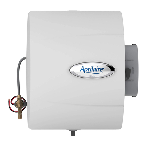
1. Front Cov r
2. Bas
3. Orific Plat
4. Motor Mount Bridg
5. Scal Control Ins rt
6. Wat r Pan l Evaporator
7. Wat r Distribution Tray
8. Fan Blad
9. Motor
10. Motor Mount Gask t
11. Control R lay
12. Pow r Cord
13. Strain R li f Bushing
14. Sol noid Valv
15. Conn ctor Plug
16. F d Tub
17. Nozzl
18. R lay Conn ctor Plug
NOTE: BEFORE LEAVING THE
JOB SITE, MAKE SURE:
1. Saddl valv is fully op n.
2. All plumbing conn ctions ar
wat rtight.
3. Humidifi r functions prop rly.
