manuals.online logo
Brands
  1. Home
  2. •
  3. Brands
  4. •
  5. APS
  6. •
  7. Inverter
  8. •
  9. APS M1P-SAA User manual

APS M1P-SAA User manual

Other APS Inverter manuals

APS YC500-A Instruction Manual

APS

APS YC500-A Instruction Manual

APS ECU-3 V3.9 User manual

APS

APS ECU-3 V3.9 User manual

APS APSG-3-5.5K-IN User manual

APS

APS APSG-3-5.5K-IN User manual

APS M1P User manual

APS

APS M1P User manual

APS YC500A-MIW Instruction Manual

APS

APS YC500A-MIW Instruction Manual

APS M1P-EU User manual

APS

APS M1P-EU User manual

Popular Inverter manuals by other brands

Omnik New Energy Omniksol-1.5k-TL user manual

Omnik New Energy

Omnik New Energy Omniksol-1.5k-TL user manual

Agilent Technologies 33250A user guide

Agilent Technologies

Agilent Technologies 33250A user guide

4-noks ZR-SWITCH-RC instruction manual

4-noks

4-noks ZR-SWITCH-RC instruction manual

V&T V5 Series user manual

V&T

V&T V5 Series user manual

Hon Turing HT-T-S1000-12 introduction

Hon Turing

Hon Turing HT-T-S1000-12 introduction

Metabo E 140 SP Plus Original operating instructions

Metabo

Metabo E 140 SP Plus Original operating instructions

BARRON EXITRONIX Tucson Micro Series installation instructions

BARRON

BARRON EXITRONIX Tucson Micro Series installation instructions

Baumer HUBNER TDP 0,2 Series Mounting and operating instructions

Baumer

Baumer HUBNER TDP 0,2 Series Mounting and operating instructions

electroil ITTPD11W-RS-BC Operation and Maintenance Handbook

electroil

electroil ITTPD11W-RS-BC Operation and Maintenance Handbook

Silicon Solar TPS555-1230 instruction manual

Silicon Solar

Silicon Solar TPS555-1230 instruction manual

Mission Critical Xantrex Freedom SW-RVC owner's guide

Mission Critical

Mission Critical Xantrex Freedom SW-RVC owner's guide

HP 3312A Operating and service manual

HP

HP 3312A Operating and service manual

Hoymiles HM-500T user manual

Hoymiles

Hoymiles HM-500T user manual

Nitecore SPM10 user manual

Nitecore

Nitecore SPM10 user manual

AEG Protect PV installation manual

AEG

AEG Protect PV installation manual

On Board TruePower Plus 1200MS owner's manual

On Board

On Board TruePower Plus 1200MS owner's manual

Plugreen PGM-200P-230 Installation and operation manual

Plugreen

Plugreen PGM-200P-230 Installation and operation manual

Fourgroup Easy use and Programming Handbook

Fourgroup

Fourgroup Easy use and Programming Handbook

manuals.online logo
manuals.online logoBrands
  • About & Mission
  • Contact us
  • Privacy Policy
  • Terms and Conditions

Copyright 2025 Manuals.Online. All Rights Reserved.

ALTENERGY POWER SYSTEM, INC.
1
APS M1P-SAA
Single-phase Micro-inverter
Installation and User Manual
Version: 4.0
!
!
ALTENERGY POWER SYSTEM, INC.
All rights reserved
ALTENERGY POWER SYSTEM, INC.
2
Contact Information
ALTENERGY POWER SYSTEM Inc.
1 Yatai Road, Jiaxing, PR China 314050
Phone: +86-21-68889199
Fax: +86-21-33928752
www.altenergy-power.com
[email protected]om
ALTENERGY POWER SYSTEM, INC.
3
Table of Contents
1.
!
Important Safety Information ......................................................................................................................... 4
!
Safety Instructions .............................................................................................................................................. 4
!
2.
!
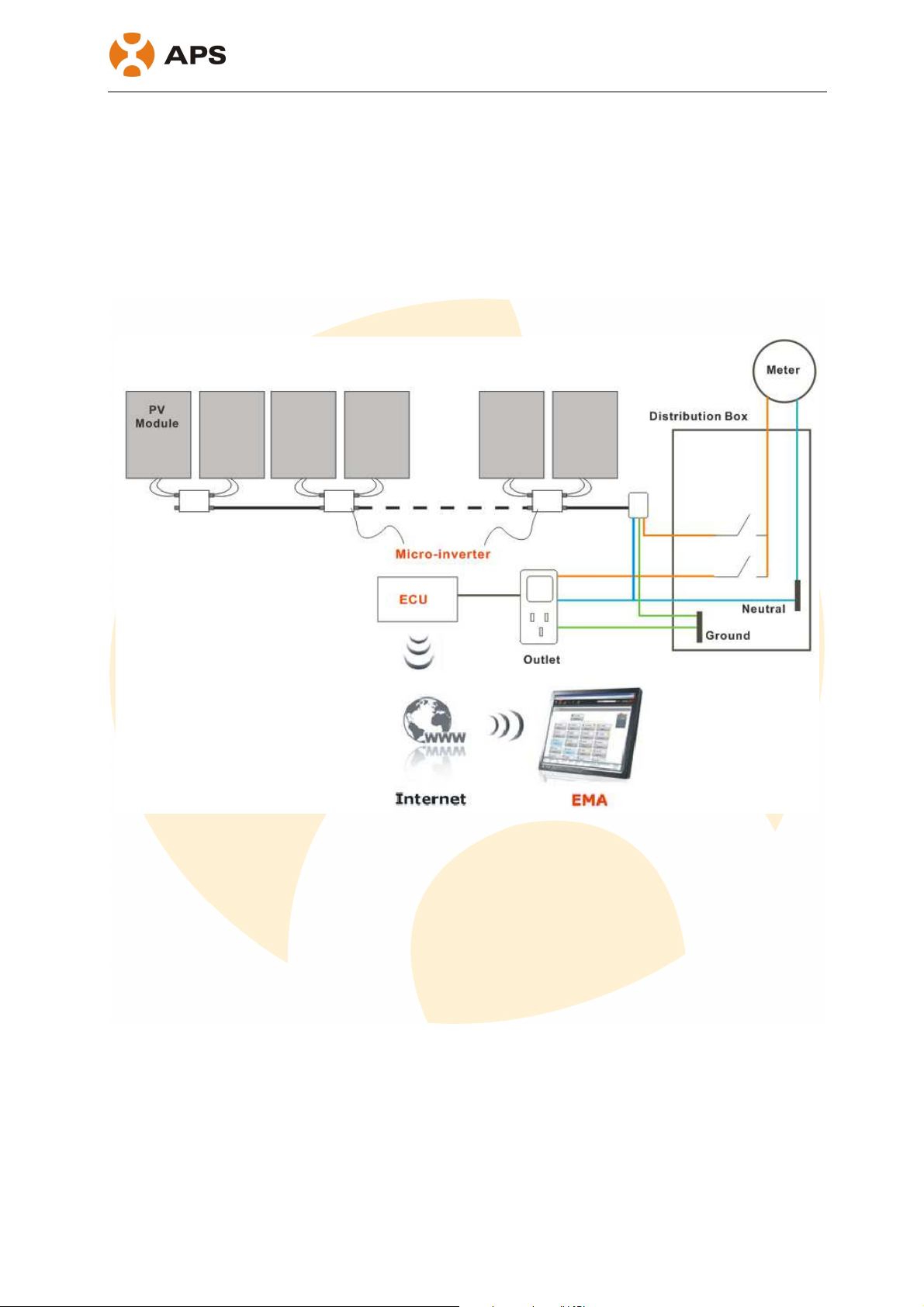
APS Micro-inverter System Introduction ....................................................................................................... 5
!
3.
!
APS Single-phase Micro-inverter M1P series ................................................................................................ 7
!
4.
!
APS Micro-inverter System Installation ......................................................................................................... 9
!
Required Parts and Tools from you .................................................................................................................... 9
!
Installation Procedures.......................................................................................................................................10
!
Step 1 - Installing the AC Branch Circuit AC Isolator...................................................................................10
!
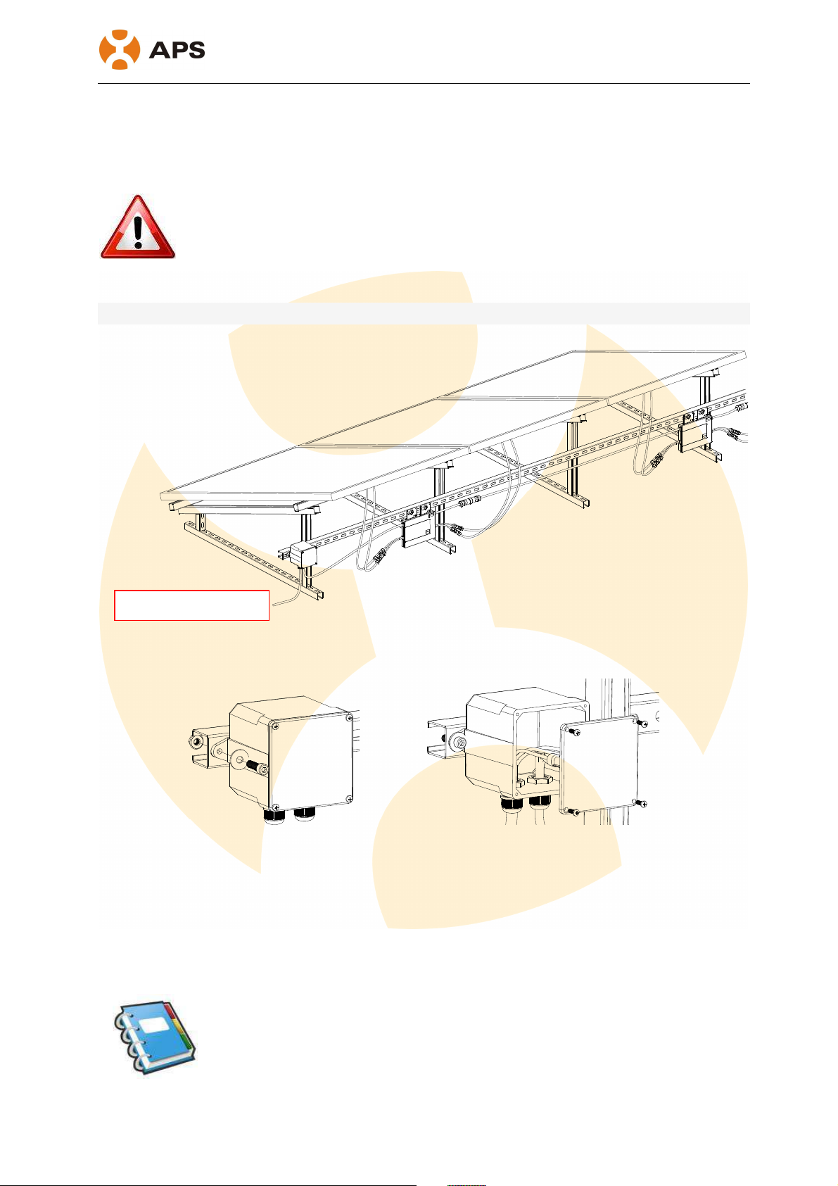
Step 2 – Attaching the APS Micro-inverters to the Racking or the PV Module Frame .................................11
!
Step 3 - Connecting the APS Micro-inverter AC Cables ...............................................................................12
!
Step 4 –Connecting APS Micro-inverters to the PV Module.........................................................................12
!
Step 5 - Completing the APS Installation Map ..............................................................................................13
!
5.
!
APS micro-inverter system operating instructions ........................................................................................14
!
6.
!
Troubleshooting.............................................................................................................................................15
!
Status Indications and Error Reporting ..............................................................................................................15
!
Operation LED ..............................................................................................................................................15
!
Other Faults ...................................................................................................................................................15
!
7.
!
Replace a micro-inverter................................................................................................................................17
!
8.
!
Efficiency Curves ..........................................................................................................................................18
!
9.
!
Technical Data...............................................................................................................................................19
!
10.
!
Wiring Diagram.........................................................................................................................................22
!
10.1
!
Sample Wiring Diagram – Single Phase ...............................................................................................22
!
10.2
!
Sample Wiring Diagram – Three Phase ................................................................................................23
!
ALTENERGY POWER SYSTEM, INC.
4
!" #$%&'()*(+,)-.(/+#*-&'$)(0&*+
This manual contains important instructions to follow during installation and maintenance of
the APS Photovoltaic Grid-connection Micro-inverter. To reduce the risk of electrical shock
and ensure the safe installation and operation of the APS Micro-inverter, the following
symbols appear throughout this document to indicate dangerous conditions and important
safety instructions.
WARNING: This indicates a situation where failure to follow instructions may
cause a serious hardware failure or personnel danger if not applied
appropriately. Use extreme caution when performing this task.
NOTE: This indicates information that is important for optimized
Micro-inverter operation. Follow these instructions closely.
!"#$%&'()*%+,-%./)*'
•Only qualified professionals should install and/or replace APS Micro-inverters.
•Perform all electrical installations in accordance with local electrical codes.
•Before installing or using the APS Micro-inverter, please read all instructions and
cautionary markings in the technical documents and on the APS Micro-inverter
system and the PV-array.
•Be aware that the body of the APS Micro-inverter is the heat sink and can reach a
temperature of 80°C. To reduce risk of burns, do not touch the body of the
Micro-inverter.
•Do NOT disconnect the PV module from the APS Micro-inverter without first
disconnecting the AC power.
•Do NOT attempt to repair the APS Micro-inverter. If it fails, contact APS Customer
Support to obtain an RMA number and start the replacement process. Damaging or
opening the APS Micro-inverter will void the warranty.
ALTENERGY POWER SYSTEM, INC.
5
1" 23,+405'&60*7.'(.'+,/8(.$+#*('&9:5(0&*+
The APS Micro-inverter is an inverter system for use in utility-interactive applications,
comprised of three key elements:
•Altenergy Power Systems Micro-inverter
•Altenergy Power Systems Energy Communication Unit (ECU)
•Altenergy Power Systems Energy Monitor and Analysis (EMA) web-based monitoring
and analysis system
This integrated system improves safety; maximizes solar energy harvest; increases system
reliability; simplifies photovoltaic (PV) system design, installation, maintenance, and
management.
The APS Micro-inverters maximize energy production from photovoltaic (PV)
arrays. Each PV module has individual Maximum Peak Power Tracking (MPPT) controls,
which ensures that the maximum power is exported to the utility grid regardless of the
performance of the other PV modules in the array. When PV modules in the array are affected
by shading, soiling, orientation, or mismatch, the APS Micro-inverter ensures top
performance from the array by maximizing the performance of each module within the array.
The APS Micro-inverter system is more reliable than centralized or string inverters.
The distributed Micro-inverter system ensures that no single point of system failure exists
across the PV system. APS Micro-inverters are designed to operate at full power at ambient
ALTENERGY POWER SYSTEM, INC.
6
temperatures of up to 65°C. The inverter housing is designed for outdoor installation and
complies with the IP65 environmental enclosure rating.
PV systems using APS Micro-inverters are very simple to install. You can install
individual PV modules in any combination of module quantity, orientation, type, and power
rate. The Ground wire (PE) of the AC cable is connected to the chassis inside of the
Micro-inverter, eliminating the installation of grounding wire.
The APS Micro-inverter system provides smart system performance monitoring
and analysis.
The APS Energy Communication Unit (ECU) is installed by simply plugging it into any wall
outlet and providing an Ethernet or Wi-Fi connection to a broadband router or modem. After
installing the ECU, the full network of APS Micro-inverters automatically reports to the APS
Energy Monitor and Analysis (EMA) web server. The EMA software displays performance
trends, informs you of abnormal events, and controls system shutdown when it is needed.
ALTENERGY POWER SYSTEM, INC.
7
!" 23,+,0*;<.6%=)8.+405'&60*7.'(.'+4!3+8.'0.8#
The APS M1P series Micro-inverters connect with the single-phase grid, and operate with
most 60,72 cell PV modules.
For more information, please see the section 8 Technical Date of
this manual.
Model
Number AC grid PV Module
Max. #
Per branch
Module Connector
YC250A 50Hz/230V 60,72 Cell 14 for 20A
breaker
MC-4 Type or Customize
YC250I 50Hz/230V 60,72 Cell 14 for 20A
breaker
MC-4 Type or Customize
YC500A 50Hz/230V 60,72 Cell 7 for 20A
breaker
MC-4 Type or Customize
YC500I 50Hz/230V 60,72 Cell 7 for 20A
breaker
MC-4 Type or Customize
YC250A 50Hz/230V 60,72 Cell 18 for 25A
breaker
MC-4 Type or Customize
YC250I 50Hz/230V 60,72 Cell 18 for 25A
breaker
MC-4 Type or Customize
YC500A 50Hz/230V 60,72 Cell 9 for 25A
breaker
MC-4 Type or Customize
YC500I 50Hz/230V 60,72 Cell 9 for 25A
breaker
MC-4 Type or Customize
ALTENERGY POWER SYSTEM, INC.
8
The following figure shows the APS YC250 micro-inverter schematic:
!
!
!
APS YC500 has two independent DC inputs, with independent MPPT control and
data monitoring.
The following figure shows the APS YC500 micro-inverter schematic:
!
!
!
ALTENERGY POWER SYSTEM, INC.
9
>" 23,+405'&60*7.'(.'+,/8(.$+#*8()<<)(0&*+
A PV system using APS Micro-inverters is simple to install. Each Micro-inverter easily mounts
on the PV racking, directly beneath each PV module. Low voltage DC wires connect from the
PV module directly to the Micro-inverter, eliminating the risk of high DC voltage.
Installation shall comply with local regulations and technical rules. Installation shall comply
with the relevant instructions of AS 4777.1 /.2& AS 3000.
WARNING: Perform all electrical installations in accordance with local electrical
codes.
WARNING: Be aware that only qualified professionals should install and/or
replace APS Micro-inverters.
WARNING: Before installing or using an APS Micro-inverter, please read all
instructions and warnings in the technical documents and on the APS
Micro-inverter system itself as well as on the PV array.
WARNING: Be aware that installation of this equipment includes the risk of
electric shock.
WARNING: Do not touch any live parts in the system, including the PV array,
when the system has been connected to the electrical grid.
WARNING: Affix warning labels to micro system components where and as
appropriate for your state/territory.
011.%./)"2'()*%"22"%./)'3/45/)$)%*'#+/4'06!
•Protective branch end cap (sold separately, 1 per branch)
•AC branch end cable (sold separately, 1 per branch)
7$8,.+$1'6"+%*'")1'9//2*'#+/4'&/,'
In addition to your PV array and its associated hardware, you need to provide the following:
•An AC isolator
•Mounting hardware suitable for module racking
•Sockets and wrenches for mounting hardware
•A Phillips screwdriver
•A torque wrench
ALTENERGY POWER SYSTEM, INC.
10
()*%"22"%./)'6+/-$1,+$*'
WARNING: Do NOT connect APS Micro-inverters to the utility grid or energize
the AC circuit until you have completed all of the installation procedures as
described in the following sections.
For bracket installation, after the completion of system installation rendering as follows:
!
!
!"#$%&%'%()*"+,,-).%"/#%01%23+)4/%1-345-"%01%(*6,+"63%
a. Install an appropriate AC isolator at a suitable location on the PV racking system
(typically at the end of a branch of modules).
b. Connect the open wire end of the AC branch end cable into the AC isolator using an
appropriate gland or strain relief fitting.
c. Wire the conductors: L- RED; N - BLACK; PE – YELLOW GREEN.
d. Connect the AC branch circuit AC isolator to the point of utility interconnection.
NOTE: Be sure to size the AC wire to account for voltage drop between the
AC branch circuit AC isolator and the point of utility interconnection. Refer to
the tables below.
Go to
distribution box