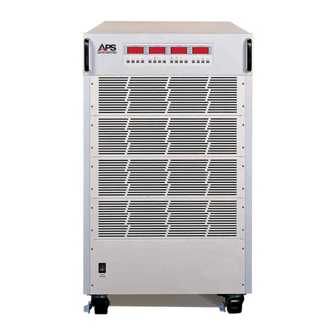
APS APS-1000 Series User manual

Operations Manual
OM-001-01000-000-04.1
APS-1000 Series
Power Converters
Entire Contents Copyright
2004 by Adaptive Power Systems, Inc. (APSI) • All Rights Reserved • No reproduction without written authorization from APSI.
ADAPTIVE Power Systems
Worldwide Supplier of Power Conversion Equipment
TM

CONTENTS
Entire Contents Copyright 2004 by Adaptive Power Systems, Inc. (APSI) • All Rights Reserved • No reproduction without written authorization from APSI.
APS-1000 Series ii OM-001-01000-000-04.0
Contents
Front Matter
Contents ....................................................................................................... ii
Contact Information..............................................................................v
Warranty Information......................................................................... vi
Chapter 1 Introduction
Introduction............................................................................................... 1-1
Overview ........................................................................................... 1-1
Safety Notices .................................................................................. 1-2
Preparation for Installation............................................................... 1-5
Installation Instructions .................................................................... 1-6
Example Wiring Diagram ................................................................ 1-7
Storage and Transportation .............................................................. 1-8
Chapter 2 Specifications
Overview .................................................................................................... 2-1
Introduction ....................................................................................... 2-2
APS-1000 Specifications ................................................................. 2-2
Input Electrical Specifications ......................................................... 2-3
Output Electrical Specifications ..................................................... 2-3
Power versus Output Frequency Rating Chart ............................... 2-4
Displays and Controls ..................................................................... 2-5
Mechanical Specifications ............................................................... 2-5
Environmental Specifications ......................................................... 2-5
Output Surge-Current Capability .................................................... 2-6

CONTENTS
Entire Contents Copyright 2004 by Adaptive Power Systems, Inc. (APSI) • All Rights Reserved • No reproduction without written authorization from APSI.
APS-1000 Series iii OM-001-01000-000-04.0
Chapter 3 Unit Description
Overview .................................................................................................... 3-1
Front Panel Organization .................................................................3-1
Frequency Display and Selection ................................................... 3-3
Voltage Display and Selection ........................................................ 3-4
Current Display and Selection ......................................................... 3-5
Power / PF Display and Selection .................................................. 3-6
Cabinet Controls and Connections ................................................. 3-7
Chassis Details .................................................................................. 3-7
Cabinet Features ............................................................................... 3-9
Chapter 4 Operating Instructions
Overview .................................................................................................... 4-1
Basic Operation ................................................................................ 4-2
Voltage (Display) Setting.................................................................4-3
Frequency (Display) Setting ............................................................ 4-5
Current Limit (Display) Setting....................................................... 4-6
Power / PF (Display) Setting ........................................................... 4-7
Operations ......................................................................................... 4-8
(Persistent) System Parameter Settings.........................................4-10
(Persistent) System Parameter Table.............................................4-11
Setting (Persistent) System Parameters.........................................4-12
Program Memory Procedures (Programming) ............................4-14
Error Messages ...............................................................................4-15
Error Message Table ......................................................................4-16
Interpreting Error Messages...........................................................4-17
Chapter 5 External Interfaces
Overview .................................................................................................... 5-1
PLC External Interface .................................................................... 5-2
Manual Switcher (Three Program Control) ................................... 5-3

CONTENTS
Entire Contents Copyright 2004 by Adaptive Power Systems, Inc. (APSI) • All Rights Reserved • No reproduction without written authorization from APSI.
APS-1000 Series iv OM-001-01000-000-04.0
Chapter 6 System Calibration
Overview .................................................................................................... 6-1
Calibration Setup ............................................................................. 6-2
Calibration Instructions ................................................................... 6-4
Low-Voltage Mode (V-LO) Calibration ........................................ 6-6
High-Voltage Mode (V-HI) Calibration ......................................... 6-7
Low-Current Mode (A-LO) Calibration ......................................... 6-8
High-Current Mode (A-HI) Calibration .......................................6-10
Low-Power Mode (P-LO) Calibration ..........................................6-12
High-Power Mode P-HI) Calibration............................................6-14
Chapter 7 System Maintenance
Overview .................................................................................................... 7-1
Introduction ...................................................................................... 7-1
System Design .................................................................................. 7-2
APS-1000 Series System Block Diagram....................................... 7-3

CONTACT INFORMATION
Entire Contents Copyright 2004 by Adaptive Power Systems, Inc. (APSI) • All Rights Reserved • No reproduction without written authorization from APSI.
APS-1000 Series vOM-001-01000-000-04.0
Contact Information
Adaptive Power Systems, Inc.
17711 Mitchell North • Irvine, CA 92614 USA
Telephone: (949) 752-8400
FAX: (949) 756-0838
E-mail: sales@adaptivepower.com
Web: http://www.adaptivepower.com

WARRANTY INFORMATION
Entire Contents Copyright 2004 by Adaptive Power Systems, Inc. (APSI) • All Rights Reserved • No reproduction without written authorization from APSI.
APS-1000 Series vi OM-001-01000-000-04.0
APS-1000 Series Power Converters Limited Warranty
Adaptive Power Systems, Inc. (APS) warrants each unit to be free from defects in material
and workmanship. For the period of one (1) year from the date of shipment to the
purchaser, APS will either repair or replace, at its sole discretion, any unit returned to the
APS factory in Irvine, California.It does not cover damage arising from misuse of the unit
or attempted field modifications or repairs. This warranty specifically excludes damage to
other equipment connected to this unit.
Upon notice from the purchaser within (30) days of shipment of units found to be defective
in material or workmanship, APS will pay all shipping charges for the repair or replacement.
If notice is received more than thirty (30) days from shipment, all shipping charges shall be
paid by the purchaser. Units returned on debit memos will not be accepted and will be
returned without repair.
This warranty is exclusive of all other warranties, expressed or implied..
APS-1000 Series Service and Spare Parts Limited Warranty
APS warrants repair work to be free from defects in material and workmanship for the
period of ninety (90) days from the invoice date. This Service and Spare Parts Limited
Warranty applies to replacement parts or to subassemblies only. All shipping and
packaging charges are the sole responsibility of the buyer. APS will not accept debit
memos for returned power sources or for subassemblies. Debit memos will cause
return of power sources or assemblies without repair.
This warranty is exclusive of all other warranties, expressed or implied.

CHAPTER 1
INTRODUCTION
Entire Contents Copyright 2004 by Adaptive Power Systems, Inc. (APSI) • All Rights Reserved • No reproduction without written authorization from APSI.
APS-1000 Series 1 - 1 OM-001-01000-000-04.0
Chapter 1
Introduction
Overview
Chapter 1 contains important information you should read BEFORE attempting to
install and power-up your APS-1000 Series Power Converter. The information in this
chapter is provided for use by experienced operators. Experienced operators
understand the necessity of becoming familiar with, and then observing, life-critical
safety and installation issues. Topics in this chapter include:
Safety Notices
Warnings
Cautions
Preparation for Installation
Installation Instructions
Transportation
Storage
Introduction to the APS-1000 Power Converter
APS-1000 Series Power Converters have been designed for long-life trouble-free
operation in the shop-floor testing environment. The input to APS-1000 units is
commercially available power at fixed voltage and frequency. The output from APS-
1000 units is programmable power at user-controlled voltages and frequencies.
There are several operational modes: (1) front panel manual control; (2) manually
programmed test sequences; (3) external control of the manually programmed
instruction test sequences.

CHAPTER 1
INTRODUCTION
Entire Contents Copyright 2004 by Adaptive Power Systems, Inc. (APSI) • All Rights Reserved • No reproduction without written authorization from APSI.
APS-1000 Series 1 - 2 OM-001-01000-000-04.0
The APS-1000 Series of Power Converters have been designed to provide frequency
and voltage conversion in a controlled test environment. Both manually adjustable and
remotely-programmable settings are provided. All APS-1000 Series Power Converters
provide 1-phase output power. Different models cover the power range from 2 kVA to
60 kVA. All units provide user-controlled 1-phase output power within the frequency
range of 45 – 500 Hz.
All APS-1000 Series units operate as double-conversion power converters. The first
conversion is AC to DC. The second conversion is DC back to AC. Three units (APS-
1002, APS-1003, and APS-1005) operate with 1-phase input power. All other units
operate with 3-phase input power. After rectification, filtering removes high-frequency
content. Low-ripple DC is subsequently converted to 1-phase AC by a high-frequency
pulse-width-modulated (PWM) switcher. Precise control is maintained by using a
highly stable digital oscillator.
APS-1000 Series Power Converters are designed for long-term continuous operation
in sheltered (no rain) environments. Because there are no batteries, APS-1000 units
operate reliably over a wide ambient temperature range. Through the use of switching
technology the equipment is efficient (about 85%). Power Converter units are
relatively tolerant of high dust environments.
Safety Notices
APS-1000 Series Power Converters can transfer very large amounts of
electrical energy very quickly.
The rapid transfer of large amounts of electrical energy is fundamental to any
high-performance power source.
Only experienced operators who have both read and understood the
information in this manual should attempt to operate the unit.
The following warnings and cautions herein must be observed at all times.

CHAPTER 1
INTRODUCTION
Entire Contents Copyright 2004 by Adaptive Power Systems, Inc. (APSI) • All Rights Reserved • No reproduction without written authorization from APSI.
APS-1000 Series 1 - 3 OM-001-01000-000-04.0
WARNINGS indicate potentially hazardous situations which, if not avoided, could result in
death or serious injury. All warnings throughout this manual will appear as follows:
–
WARNING
IF THIS EQUIPMENT IS NOT USED IN A MANNER SPECIFIED BY THE MANUFACTURER,
THE PROTECTION PROVIDED BY THE EQUIPMENT MAY BE IMPAIRED
WARNING
THIS EQUIPMENT CONTAINS HIGH ENERGY, LOW IMPEDANCE CIRCUITS!!
LETHAL POTENTIALS ARE CONTAINED WITHIN THE CABINET.
CARE MUST BE EXERCISED WHEN OPERATING, CALIBRATING, OR SERVICING
THIS EQUIPMENT, IN ORDER TO PREVENT SERIOUS OPERATOR INJURY OR
EQUIPMENT DAMAGE.
OBSERVE THE FOLLOWING WHEN SERVICE AND MAINTENANCE ARE REQUIRED:
1) REMOVE ALL JEWELRY FROM ARMS AND NECK WHEN SERVICING THIS
EQUIPMENT. THIS PREVENTS THE POSSIBILITY OF SHORTING THROUGH THE
JEWELRY AND CAUSING BURNS TO THE OPERATOR.
2) WEAR SAFETY GLASSES WHEN SERVICING THIS EQUIPMENT TO PREVENT EYE
INJURY DUE TO FLYING PARTICLES CAUSED BY ACCIDENTAL SHORT CIRCUIT
CONDITIONS.
3) DO NOT REMOVE ANY PANEL OR COVER WITHOUT FIRST REMOVING THE INPUT
POWER BY OPENING ALL CIRCUIT BREAKERS.
4) SERVICE OTHER THAN REGULARLY SCHEDULED CALIBRATION OR EXTERNAL
CLEANING SHOULD BE REFERRED TO PERSONNEL AUTHORIZED BY THE
FACTORY TO SERVICE THIS EQUIPMENT.

CHAPTER 1
INTRODUCTION
Entire Contents Copyright 2004 by Adaptive Power Systems, Inc. (APSI) • All Rights Reserved • No reproduction without written authorization from APSI.
APS-1000 Series 1 - 4 OM-001-01000-000-04.0
CAUTIONS indicate a potentially hazardous situation which, if not avoided, may result
in minor or moderate injury. It also may be used to alert against unsafe practices.
Cautions will appear as shown below. All cautions should be rigorously observed.
CAUTION
Read the INSTALLATION and OPERATION instructions
of this manual before installing or operating this equipment.
To protect the equipment from damage, caution statements are used as follows:
CAUTION
Refer to INDUSTRY STANDARDS for the safe correct size of the power
input cables. The incorrect use of small-gauge input cables may cause
overheating and damage the cables or the equipment.
•Before using this AC converter, please read all the safety labels that are attached
to this unit.
•Before turning on the input power source to this equipment, please check to make
sure that the input voltage selection is correct.
WARNING
Before turning on the input power source to this equipment,
please check to make sure that a good earth ground is con
nected
to the proper terminal.

CHAPTER 1
INTRODUCTION
Entire Contents Copyright 2004 by Adaptive Power Systems, Inc. (APSI) • All Rights Reserved • No reproduction without written authorization from APSI.
APS-1000 Series 1 - 5 OM-001-01000-000-04.0
Preparation for Installation
Important Information and Instructions
This section contains instructions for unpacking, inspecting, preparing and storing your
APS-1000 Power Converter.
Unpacking and Inspection
APS-1000 Power Converters are well packed to provide protection in the normal
shipping environment. If the shipping box appears damaged upon receiving, please
inspect the power source for scratches or damage. If the product has been damaged,
please alert the freight company and contact APS or the distributor. Please keep the
original box and packing to assist in determining how the damage occurred.
What to do if Damage has Occurred
If your APS-1000 Power Converter was damaged in shipment, you must file a damage
claim with the freight company. Do not return the product before contacting APS to
receive a Returned Merchandise Authorization (RMA) number.
Please retain all the original packing materials. If the APS-1000 Power Converter must
be sent back for repair, use the original packing materials for packing.

CHAPTER 1
INTRODUCTION
Entire Contents Copyright 2004 by Adaptive Power Systems, Inc. (APSI) • All Rights Reserved • No reproduction without written authorization from APSI.
APS-1000 Series 1 - 6 OM-001-01000-000-04.0
Installation Instructions
Input and Output Circuit Breakers
APS-1000 Power Converter input and output circuit breakers and their connections are
on the rear of the unit. Please check to make sure all wires are connected correctly and
secured. Cooling fans, located at the sides and rear of the unit, provide air circulation
for cooling and heat removal.
A typical wiring diagram is shown on the following page.
AC Line Input Current Requirements
TheAC input requirement for the APS Power Converter depends on the configured AC
input voltage and total power level of the specific APS 1000 model. For three phase
AC input models, the current shown in the table below is for each phase.
Input wire sizes must be chosen to support the maximum currents shown in this table
and must conform to local electrical safety codes. Note that these values are based on
the AC input circuit breaker rating for each model. The actual AC input currents are
lower than the values shown.
AC Line Input Current Requirements
Model
1003
1005
1010
1020
1030
1040
1060
Input Phase
1-phase / 2-wire +
GND
3-phase
Rated Power
Total Power
3 KVA
5 KVA
10 KVA
20KVA
30KVA
40KVA
60KVA
Phase
230V, 1ø
20 A
36 A
-
-
-
-
-
208V, 3ø
-
-
40 A
100 A
125 A
175 A
250 A
220V, 3ø
-
-
40 A
100 A
125 A
150 A
250 A
240V, 3ø
-
-
40 A
75 A
100 A
150 A
225 A
380V, 3ø
-
-
30 A
50 A
75 A
100 A
150 A
415V, 3ø
-
-
20 A
40 A
60 A
100 A
125 A
480V, 3ø
-
-
20 A
40 A
50 A
75 A
125 A

CHAPTER 1
INTRODUCTION
Entire Contents Copyright 2004 by Adaptive Power Systems, Inc. (APSI) • All Rights Reserved • No reproduction without written authorization from APSI.
APS-1000 Series 1 - 7 OM-001-01000-000-04.0
Input Voltage Requirement and Selection
APS-1000 Series Power Converters are delivered with a universal input transformer.
You will receive your unit factory-connected and tested at the voltage specified at the
time of order. Please check the unit data plate to verify the voltage is correct.
Operating Environment
APS-1000 Series Power Converters are designed to operate reliably over a wide range
of environmental conditions. Please operate within the following limits:
Temperature: 0 °C – 40 °C (32 °F – 104 °F)
Humidity: 20% – 80% (Non-condensing)
Altitude: Below 2,000 meters (6,500 feet) of elevation

CHAPTER 1
INTRODUCTION
Entire Contents Copyright 2004 by Adaptive Power Systems, Inc. (APSI) • All Rights Reserved • No reproduction without written authorization from APSI.
APS-1000 Series 1 - 8 OM-001-01000-000-04.0
Example Wiring Diagram
INPUT / OUTPUT Power Panel at Rear of APS Unit (typical)
WARNING
THIS EQUIPMENT CONTAINS HIGH ENERGY, LOW IMPEDANCE CIRCUITS!!
LETHAL POTENTIALS ARE CONTAINED WITHIN THE CABINET.
ONLY FULLY-QUALIFIED PERSONNEL SHOULD ATTEMPT TO MAKE INPUT
OR OUTPUT POWER CONNECTIONS.
N G L G N C B A
OUTPUT CONNECTIONS INPUT CONNECTIONS
NOTE: Input Terminal Phases R, S, T are North American (U.S.) A, B, C
NOTE: Other terminal configurations are possible. For example, there is
no neutral terminal for 3-phase delta-winding inputs. In addition,
depending on voltage range, there may be no neutral terminal. All units
provide 1-phase outputs. Inputs are 3-phase, except for APS-1002, APS-
1003, and APS-1005, which have 1-phase inputs (2-wire plus ground).

CHAPTER 1
INTRODUCTION
Entire Contents Copyright 2004 by Adaptive Power Systems, Inc. (APSI) • All Rights Reserved • No reproduction without written authorization from APSI.
APS-1000 Series 1 - 9 OM-001-01000-000-04.0
Storage and Transportation
Packing Instructions
Please retain all the original packing materials. If the equipment must be sent back for
repair, use the original packing materials for packing. Please contact the APS repair
center or factory before returning equipment. Be sure to send all accessories and
indicate the symptoms and cause of failure if known.
Other packing Material
If the original packing material is missing, please follow the instructions below:
Wrap the equipment in PU (polyurethane) foam or Styrofoam.
The equipment must be protected by shock-resistant material, about 70 to 100mm
thick (3 to 4 inches).
The front panel must be protected with cardboard.
Secure packing tightly and insert unit into a wooden crate if possible.
Label the box “fragile” and transport carefully.
Non-Operating Environment
The APS-1000 Series Frequency Converter can be stored and transported under the
following environment:
Temperature: –40 °C – 55 °C ( –40 °F – 131 °F)
Altitude: 7,620 meters (25,000 feet)
Avoid sudden temperature changes. Sudden changes in temperature may result in
condensation inside the equipment.

CHAPTER 2
TECHNICAL SPECIFICATIONS
Entire Contents Copyright 2004 by Adaptive Power Systems, Inc. (APSI) • All Rights Reserved • No reproduction without written authorization from APSI.
APS-1000 Series 2 - 1 OM-001-01000-000-04.0
Chapter 2
Specifications
Overview
Chapter 2 summarizes the capabilities and general features of the APS-1000 family of
Power Converters. Functional capabilities are similar for all units. APS units convert
fixed line voltage at a fixed frequency to user-selected 1-phase output voltages and
frequencies. The primary differences between units are size, weight, type of external
data interface, and specific power handling capability. All units provide built-in PLC
remote control for three program memories.
The Displays and Controls Table in this section provides summary information about
the programmable memories and external control. More detailed information about
external interface control is found in Chapter 5.
This Chapter includes five summary tables and a surge-current performance graph. The
tables summarize different capabilities and features of APS-1000 Power Converters.
The graph illustrates over-current (start-up surge-current) capabilities.
Introduction
APS-1000 Power Converters are rugged versatile workhorses. The intended location
for APS-1000 units is the test floor, not a laboratory workbench. The smallest unit, the
APS-1002, weights 177 lbs. The largest unit, the APS-1060, weighs 1960 lbs. Users
can select from several modes of operation:
full-manual operation
manually programmed operation
remote PLC operation

CHAPTER 2
TECHNICAL SPECIFICATIONS
Entire Contents Copyright 2004 by Adaptive Power Systems, Inc. (APSI) • All Rights Reserved • No reproduction without written authorization from APSI.
APS-1000 Series 2 - 2 OM-001-01000-000-04.0
In keeping with their workhorse nature, all APS-1000 units feature a 200% start-up
surge-current capability. The ability to source initial surge currents prevents the
programmed over-current protection from disabling a test.
APS-1000 Specifications
The following five tables and surge current graph provide detailed information about
the entire family of APS-1000 Series of power converters.
Input Electrical Specifications
Output Electrical Specifications
Displays and Controls
Mechanical Specifications
Environmental Specifications
Surge-Current Rating Graph

CHAPTER 2
TECHNICAL SPECIFICATIONS
Entire Contents Copyright 2004 by Adaptive Power Systems, Inc. (APSI) • All Rights Reserved • No reproduction without written authorization from APSI.
APS-1000 Series 2 - 3 OM-001-01000-000-04.0
Input Electrical Specifications
Model
1003
1005
1010
1020
1030
1040
1060
Input Phase
1-phase / 2-wire + Ground
3-phase
Input Voltage(VAC L/L)
230 V ± 15%
208,220,240(3W+G)380,415,480(4W+G)±10%
Input Frequency
47 – 63 Hz
Output Electrical Specifications
Total Power
3 KVA
5 KVA
10 KVA
20 KVA
30 KVA
40 KVA
60KVA
Maximum
Amps
0 – 150 V 25.2 A 42.0 A 84.0 A 168.0 A 252.0 A 336.0 A 504.0 A
0 – 300 V
12.6 A
21.0 A
42.0 A
84.0 A
126.0 A
168.0 A
252.0 A
Phase
1-phase / 2-wire + Ground
Voltage
Low Range
0 – 150 V
High Range
0 – 300 V
Resolution
0.1 V
Accuracy
±(1% + 0.2 V)
Frequency
Range
45 – 500 Hz
Resolution
0.1 Hz at 45 – 99.9 Hz, 1 Hz at 100 – 500 Hz
Accuracy
±
0.2%
Parameters
1003P
1005P
1010P
1020P
1030P
1040P
1060P
Current
Range
L 0.000 – 3.5 A 0.00 – 35.00 A 0.0-350A
H
3.00 – 35.00 A
30.00 – 350.0 A
300-3500A
Resolution
L
0.001 A
0.01 A
0.1A
H
0.01 A
0.1 A
1A
Accuracy
L
±(1% of reading + 0.005
±(1% of reading + 2 counts)
H
±(1% of reading + 0.01 A)
±(1% of reading + 1 count)
Power
Range
L
0.0 – 350.0 W
0.000 – 3.500 kW
0.0-35.0kW
H
300 – 5000 W
3.00 – 60.00 kW
30.0-
Resolution
L
0.1 W
0.001 kW
0.01kW
H
1 W
0.01 kW
0.1kW
Accuracy
L ±
(1.5% of reading + 0.5
±
(1.5% of reading + 5 counts)
H
±(1.5% of reading + 1.0
±(1.5% of reading + 1 count)
Power
Factor
Range
0.001 – 1.000
Resolution
0.001
Accuracy
Depends on the accuracy of V, A, W
Harmonic Distortion
≤
1% (Resistive Load)
Crest Factor
≥3 to 1
Load Regulation
±
0.5%
Protection
Over-Current, Short-Circuit, Over-Temperature
Efficiency ≥
85% (at full load)

CHAPTER 2
TECHNICAL SPECIFICATIONS
Entire Contents Copyright 2004 by Adaptive Power Systems, Inc. (APSI) • All Rights Reserved • No reproduction without written authorization from APSI.
APS-1000 Series 2 - 4 OM-001-01000-000-04.0
Power versus Output Frequency Rating Chart
The following thermal ratings apply to models 1020, 1030 and 1040 as a function of
load and programmed output frequency at an ambient temperature of 25°C. This
derating is caused by heat build-up in the output transformer.
Output load ratings expressed as restive load reflecting % of full load for frequency
ranges at which the power source can operate continuously are as follows:
45Hz ~ 100Hz 90% resistive load
< 200Hz 77% resistive load
< 300Hz 65% resistor load
< 400Hz 52% resistor load
< 500Hz 40% resistor load
At an output frequency of 500Hz and output power into 70% resistor load, the power
source can operate for a period of 15 minutes then instrument output will shut down
because output transformer is too hot.
10%
20%
30%
40%
50%
60%
70%
80%
90%
100%
50
100
200
300
400
500
150
250
350
450
15min
30min
Continuity
Power
Frequency(Hz)
Resistor
Load

CHAPTER 2
TECHNICAL SPECIFICATIONS
Entire Contents Copyright 2004 by Adaptive Power Systems, Inc. (APSI) • All Rights Reserved • No reproduction without written authorization from APSI.
APS-1000 Series 2 - 5 OM-001-01000-000-04.0
Mechanical Specifications
Model 1003 1005 1010 1020 1030 1040 1060
Power Rating
3 KVA
5 KVA
10 KVA
20 KVA
30 KVA
40 KVA
60KVA
Dimensions (In.) H
12
12
28
33
43
43 66
D 26 26 29 29 39 39 39
W
17
17
17
17
24
24 32
Weight Kg 95 125 228 350 592 663 885
lbs
210
275
503
772
1305
1462
1951
Displays and Controls
Model 1003 1005 1010 1020 1030 1040 1060
4 Digital LED
meters
Frequency, Voltage, Current, Power or Power Factor (simultaneously)
PLC Remote Output ON/OFF
Selection of programmable memories: P1, P2, P3
Memory 8 Memories, 5 Programmable Steps per Memory for:
Voltage, Frequency, Test Time, Delay Time, Current, Power, and
Power Factor Hi/Lo Limit Setting
Note: Programmable memories can be manually programmed and used independently of the
External RS-232 or GPIB Interface. They can also be independently programmed through
these external interfaces.
Calibration Front Panel Calibration
PLC
(external)
Interface
PLC interface controls execution of programmed steps in Memories 1, 2, or 3.
The PLC interface is a standard feature of all APS Power Converters.
Auto-Voltage
Adjust
Provides improved voltage regulation
Environmental Specifications
Operating Temperature 32 ºF – 104 ºF (0 ºC – 40 ºC)
Relative Humidity < 80 % (Non-condensing)
Altitude ≤ 6,500 feet
This manual suits for next models
7
Table of contents
Other APS Media Converter manuals