APS CP 295 MRS Use and care manual

CP295MRS CP305MRS CP405MRS Technical reference - Rev. K 1
Advanced Printing Systems
CP 295 MRS CP 305 MRS CP 405 MRS

CP295MRS CP305MRS CP405MRS Technical reference - Rev. K 2
Advanced Printing Systems
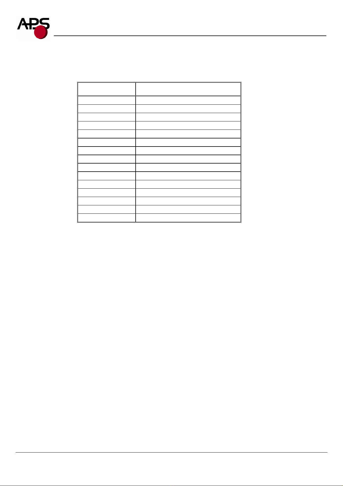
1. TABLE OF CONTENTS
CP 295 MRS........................................................................................................................................................... 1
CP 305 MRS........................................................................................................................................................... 1
CP 405 MRS........................................................................................................................................................... 1
1. Table of contents ........................................................................................................................................ 2
2. General features.......................................................................................................................................... 3
3. Revision history.......................................................................................................................................... 4
4. General specifications ................................................................................................................................ 5
5. Printer Device Interconnection................................................................................................................... 6
5.1 Power supply connector ..................................................................................................................... 6
5.2 Serial communication connector ........................................................................................................ 6
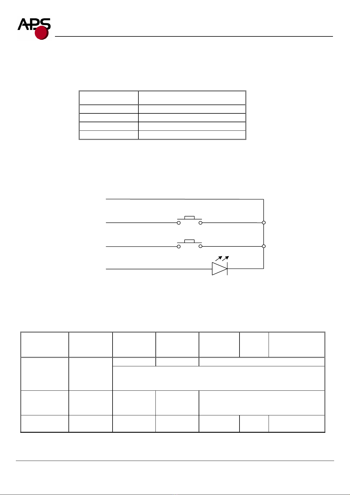
5.3 Switch/Led connector......................................................................................................................... 7
5.4 Parallel communication connector ..................................................................................................... 8
5.5 Sleep mode disable connector ............................................................................................................ 8
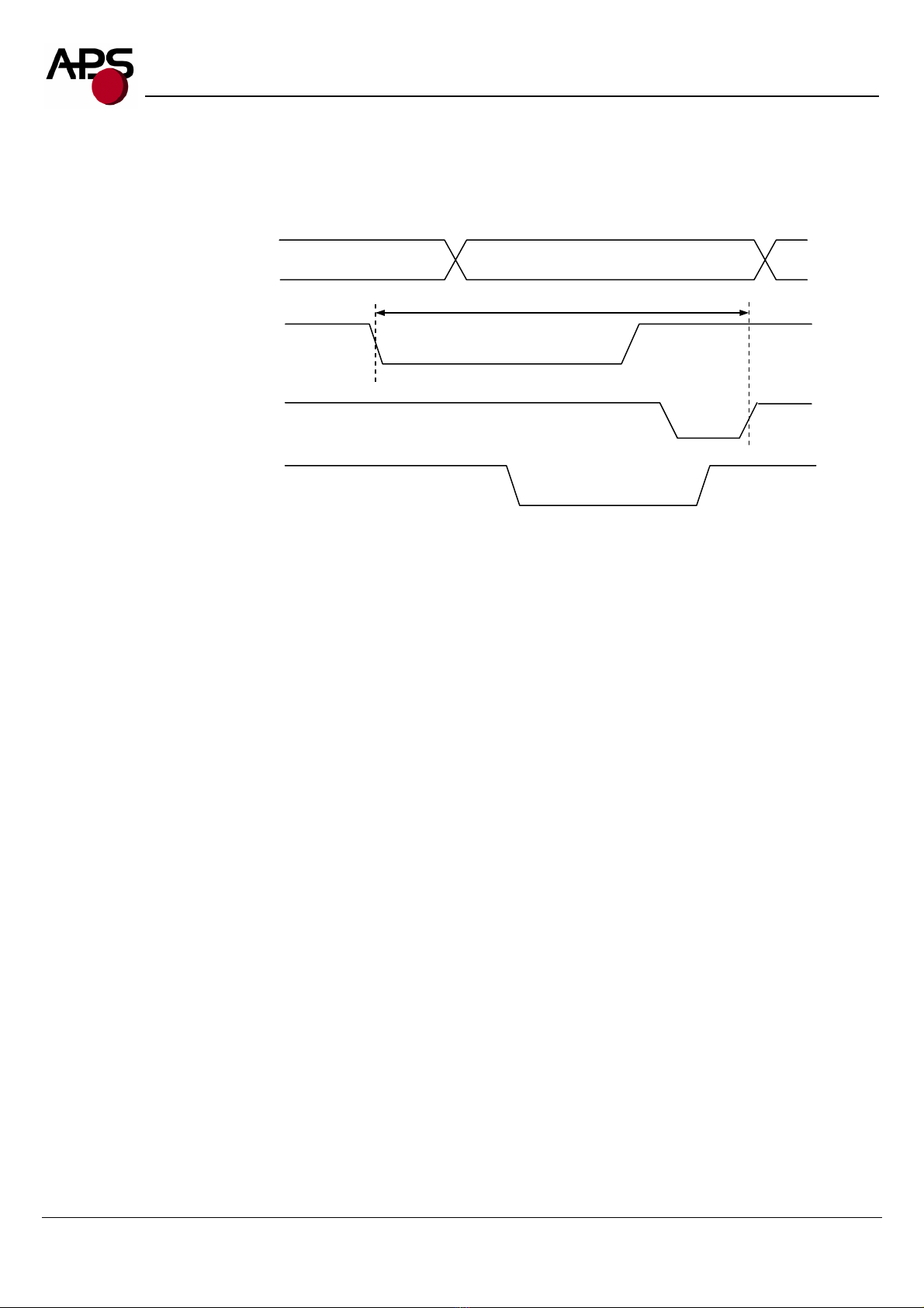
5.6 Timing for parallel communication.................................................................................................... 9
5.7 Serial / Parallel mode selection ........................................................................................................ 10
5.8 Near end of paper sensor .................................................................................................................. 11
6. Printer Device Operations ........................................................................................................................ 12
6.1 Self test Mode................................................................................................................................... 12
6.2 Paper loading.................................................................................................................................... 13
6.3 Text Printing Format ........................................................................................................................ 14
6.4 Operating Control codes................................................................................................................... 16
7. Ordering code ........................................................................................................................................... 38
http://www.aps-printers.com/
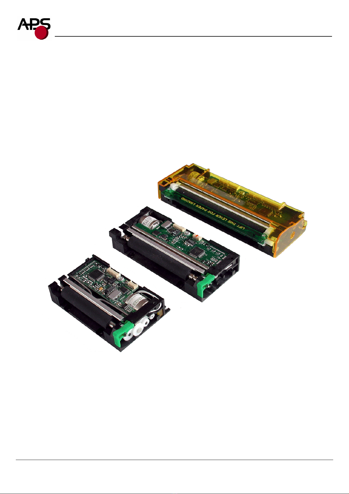
This manual provides complete information about APS CP295MRS, CP305MRS, CP405MRS printer.
A.P.S. reserves the right to make changes without notice to the product to improve reliability, function or design.
A.P.S. does not assume any liability arising out of the application or use of the product or circuit described herein.

CP295MRS CP305MRS CP405MRS Technical reference - Rev. K 3
Advanced Printing Systems
2. GENERAL FEATURES
The CP295MRS, CP305MRS and CP405MRS are the world’s first 2 inch, 3 inch and 4 inch, 5 Volt thermal
printer mechanisms with an integrated control board using serial and parallel communications. The height of
the mechanisms plus board is less than 27 mm, which makes them the most compact 2 inch, 3 inch and 4 inch,
5Volts thermal line printing solution available today.
!Ultra-compact printers
CP295MRS Total size W91 x H20 x D55
CP305MRS Total size W121 x H20 x D55
CP405MRS Total size W156 x H27 x D55
No wire or connector exiting this volume
!Fully hot plug printers
!Software programmable consumption
Dynamic division, and high speed (up to 60mm/s)
!Full control over printing quality/speed
Speed clamping, acceleration smoothing… via control codes
!Sleep mode
Current consumption <10nA
Wake-up on serial/parallel port or external switch
!External pluggable switches and LED for easy integration
!Single power supply
From 5 Volts to 8.5 Volts
!2 Communication ports
RS232 (speed up to 115 200 Bds)
Centronics
!Three internal fonts
Easy font update
!Powerful Text Printing Modes
Horizontal
180 degree
Double and Quadruple width and height printing
Inverse video
!Powerful Graphic Modes
Variable width and offset
Double width and height
!Hole / Mark Detection
!Cutter driving
Guillotine cutter type
!10 Barcodes
Normal and 90 degree
!Supports reflective and transmissive optocouplers
!Printing parameters can be saved in flash
!Supports easy single-sheet insertion /ejection
!Optional near end of paper optosensor
!Windowsdrivers available
!Easy firmware upgrades (please contact A.P.S)

CP295MRS CP305MRS CP405MRS Technical reference - Rev. K 4
Advanced Printing Systems
3. REVISION HISTORY
REV. DATE PAGE REVISION ITEM
A 08/Jul/99 -
First issue
B 16/Jul/99 -
Switch/Led connector + 80 columns font change
C 05/Nov/99 -
Led flashing + control code corrections +
connectors location on drawing
D 1/Dec/00 -
1.35, 1.36 firmware revision:
No black mark detection
E 1/Mar/01 -
1.37 firmware revision:
Black mark detection supported
F 1/Sep/01 -
5.0 firmware revision:
Three internal fonts, inverse video, different
widths mixed on same line, acceleration
smoothing, text justification, rotated barcodes,
support for both reflective and transmissive
optocouplers.
5.0 supports older hardware (saturated opto).
5.1 supports new hardware (linear opto).
G 15/Apr/02 -
5.2 and 5.3 firmware revision :
enhanced opto support with calibration.
5.2 supports older hardware (saturated opto).
5.3 supports new hardware (linear opto).
- 10/Oct/02 -
Print mechanism name can be customized by
software. Setup parameters can be saved in flash
and restored to default values. Support for single
sheet applications.
- 24/Feb/03 -
Firmware revisions 5.40 / 5.50
Feature set identical to 5.2 / 5.3
- 19/Mar/03 -
Fimrware revisions 5.41 / 5.51
Minor enhancements.
H 15/Apr/03 -
Firmware revisions 5.42 / 5.52
Minor enhancements.
I 04/Sep/03 -
Firmware revisions 5.45 / 5.55
Autosleep parameter saved in flash, linear opto
enhancement
Near end of paper feature added
J 22/Oct/03 -
Firmware revisions 5.46 / 5.56
Updated RS232 parameters saving.
K 04/Jun/04 -
Firmware revisions 5.47 / 5.57
Added ticket eject direction (GS d n)
Near end of paper hardware update.

CP295MRS CP305MRS CP405MRS Technical reference - Rev. K 5
Advanced Printing Systems
4. GENERAL SPECIFICATIONS
ITEM SPECIFICATION
Print method Thermal dot-line printing
Dimension WxDxH (mm) CP295MRS 91 x 55 x 20
CP305MRS 121 x 55 x 20
CP405MRS 156 x 55 x 27
Total dots CP295MRS 384
CP305MRS 576
CP405MRS 832
Dot density 8 dots/mm
Paper width CP295MRS 60 mm
CP305MRS 80 mm
CP405MRS 114 mm
Print width
(centered on paper) CP295MRS 48 mm
CP305MRS 72 mm
CP405MRS 104 mm
Heat element pitch 0.125 mm
Paper feed pitch 0.125 mm
Paper feed tension 50g or more
Paper hold tension 80g or more
Recommended Paper KF50-HDA or equivalent
Voltage range 5Volts to 8.5Volts
Current consumption From 1.5A to 5Amp ( @5V )
Operating temperature From -10°C to +60°C
Operating humidity (RH%) 20-85 (no condensation)
Storage temperature (°C) From -40°C to +90°C
Storage humidity (RH%) 10-90 (no condensation)
EMC standard Designed to comply with Level B – FCC - CE

CP295MRS CP305MRS CP405MRS Technical reference - Rev. K 6
Advanced Printing Systems
5. PRINTER DEVICE INTERCONNECTION
Please refer to the drawing attached to back of this specification for connect or positions.
These printers are fully hot plug : any connector hereafter can be connected or disconnected without damaging
the printer.
5.1 Power supply connector
Connector J1: MOLEX, 53048 Series 9 contacts. Female 51021 Series contacts 50079/50058.
Power supply (V bat) is from 5v to 8.5v DC. Maximum current is 5A @ 5V (peak for 3ms). In OFF mode the
printer’s consumption is less than 10nA.
PIN NUMBER SIGNAL NAME
1 GND
2 GND
3 GND
4 GND
5 GND
6 V bat
7 V bat
8 V bat
9 V bat
IMPORTANT NOTE:
Wires AWG28 must be used in order to avoid current losses
5.2 Serial communication connector
Connector J2: MOLEX, 53048 Series 5 contacts. Female 51021 Series contacts 50079/50058.
PIN NUMBER SIGNAL NAME
1 Gnd
2 Transmit data (Txd, printer output)
3 Receive data (Rxd, printer input)
4 CTS/DSR (printer input)
5 RTS/DTR (printer output)

CP295MRS CP305MRS CP405MRS Technical reference - Rev. K 7
Advanced Printing Systems
5.3 Switch/Led connector
Connector J3: MOLEX, 53048 Series 4 contacts. Female 51021 Series contacts 50079/50058.
PIN NUMBER SIGNAL NAME
1 Gnd
2 ON/OFF line
3 Paper FEED
4 LED (cathode)
This connector allows you to design an external paper feed button, on-line off-line button, and status LED.
External circuitry is as follows:
(*) A serial resistor (470 Ohms) is on the printer, setting the LED current at about 7 mA.
The Switches and LED functions are defined in the following table:
Printer Status OFF OFF Line On Line Head-up
End of
Paper
Over/Under
Voltage or
Temperature
On Line Off Line N/AOn/Off Line
SW
Execute self-
test if pressed
during
Power-On
Switch OFF the printer if pressed more than 2.5 seconds
Paper Feed
Switch
Switch On
the Printer
Feeds Paper Feeds Paper
if not already
printing
N/A
LED OFF 1 Flash “ON” Always "ON" 2 Flash
“ON”
3 Flash
“ON”
4 Flash “ON”
Pin 1 - Gnd
Pin 2 - ON/OFF
Pin 3 - Paper
Pin 4 - LED

CP295MRS CP305MRS CP405MRS Technical reference - Rev. K 8
Advanced Printing Systems
5.4 Parallel communication connector
Connector J4: MOLEX, 53048 Series 15 contacts. Female 51021 Series contacts 50079/50058.
PIN NUMBER SIGNAL NAME
1 \AUTOFEED
2 BUSY
3 D7
4 D6
5 D5
6 D4
7 D3
8 D2
9 D1
10 D0
11 PE
12 \INIT
13 GND
14 \STB
15 \ACK
5.5 Sleep mode disable connector
Connector J5: MOLEX, 53048 Series 2 contacts. Female 51021 Series contacts 50079/50058.
The printer is shipped with sleep mode enabled at power up, thus the contacts on this connector are not wired
together. If pin 1 and 2 are wired together, the sleep mode feature is disabled.
See "Switch/Led connector" and "ESC S" control code for more details about the sleep mode.

CP295MRS CP305MRS CP405MRS Technical reference - Rev. K 9
Advanced Printing Systems
5.6 Timing for parallel communication
The communication protocol is Centronics compatible, and has the ability to handle the “Compatibility Mode”
(Write from the Host to the Printer), and also the “Byte Mode”, for the host to read internal data from the
printer. The “Byte Mode” is used to receive printer status back from the printer.
5.6.1 Compatibility mode timing (host writes to the printer)
PARAMETER MIN TYP MAX COMMENTS
Time STB (tSTB) 5 µs - - This time is given by the host
Time BUSY (tBUSY) 25 µs 90 µs 250 µs This hold time is controlled by GS b
control code
Time tVALDATA 25 µs - -
Time in while the data must be
stable. This time is fixed by the
host.
Time ACK (tACK) - 3µs -
IMPORTANT NOTE:
The data (D0-D7) must be stable for tVALDATA. If not, please contact APS for additional cabling.
D0-D7 (Host Output)
STB
(
Host Out
p
ut
)
BUSY (Printer Output)
ACK (Printer Output)
DATA VALID
tSTB
tAC
K
tBUSY
tVALDATA

CP295MRS CP305MRS CP405MRS Technical reference - Rev. K 10
Advanced Printing Systems
5.6.2 Byte Mode timing (host reads data from printer)
In this mode, the data transfer controlled is given by the host, but tCycle must not exceed 0.5 seconds
5.7 Serial / Parallel mode selection
Serial or Parallel mode will be chosen via software automatically after the first character is received. At power-
up, both serial and parallel communications are active. If the first character is received on the serial port, the
communication will be serial, and vice versa for parallel. This first character will be interpreted like any other
incoming byte into the printer.
D0-D7 (Printer Output)
\AUTOFEED
(
Host Out
p
ut
)
STROBE (Host Output)
ACK (Printer Output)
DATA VALID
TC
y
cle

CP295MRS CP305MRS CP405MRS Technical reference - Rev. K 11
Advanced Printing Systems
5.8 Near end of paper sensor
It is possible to add a near end of paper detection feature to all printers. The near end of paper is an extension
available on the parallel communication connector. The usage of this extension disables the parallel
communication feature.
This extension is available for purchase from A.P.S as a small board with mounting holes and a four point
connector. See photo below.
The actual size can be seen on the photo. The dark rectangle is the
optosensor. The connector and passive components are on the other
side for easier mounting.
It uses a reflective optosensor placed near the end of the paper roll, and will preventively detect the fact that the
roll will soon have to be changed.
A cable with the corresponding 4 points on one end and 15 points on the other will connect to appropriate
signals on the parallel port. A loopback on the 15 points side will allow the firmware to detect the presence of
the extension and configure the required pins correctly for operation of the optosensor. See cabling and
optosensor board schematics below.
When this feature is used, the parallel port functionnality is disabled. Due to variations in optosensor
specifications, and different mounting positions, it will generally be necessary to perform a calibration
procedure. This is very straightforward, as the firmware has a command that will automatically perform a
reflection measurement, determine an appropriate threshold, and permanently store it in the flash memory of
the microcontroller. This is normally done only once in production. The application software can query for the
near end of paper status, and the firmware will respond with a single yes/no answer.
Please refer to the “Near end of paper” control codes (“ESC n” commands set) in section 6.4.2 for more
information.

CP295MRS CP305MRS CP405MRS Technical reference - Rev. K 12
Advanced Printing Systems
6. PRINTER DEVICE OPERATIONS
6.1 Self test Mode
This mode is done by the combination of the 2 external switches (see section 5.3). It prints the printer type, the
revision of the printer firmware, the logic voltage, the serial port settings, all internal character sets, and product
code.
12x20 Internal Character set
Printer type
Firmware Revision
8x16 Internal Character set
7x16 Internal Character set
Logic voltage

CP295MRS CP305MRS CP405MRS Technical reference - Rev. K 13
Advanced Printing Systems
6.2 Paper loading
Paper loading can be achieved by two different methods:
•Automatic paper loading: With the green head-up lever in the down position, insert the paper inside the
printer, and then the roller will automatically feed the paper for about 40 mm. If the printer has a cutter, the
cutter will cut the paper after the loading. The printer is then ready to print. This function can be achieved
only if power supply is more than 5 volts. In mark detection mode, the paper is fed forward to the TOF
position.
•Manual paper loading: Put the green head-up lever in the up position. Manually feed the paper into the
printer until it exits between the thermal head and the roller. Turn the green lever to the head-down position.
Now the printer is ready to print.

CP295MRS CP305MRS CP405MRS Technical reference - Rev. K 14
Advanced Printing Systems
6.3 Text Printing Format
The controller board has three resident sets of 224 characters : 8x16, 12x20, and 7x16.
The 8x16 and 12x10 fonts include the Euro currency symbol (Position 128, 80h).
12 characters are selectable from the international character set : refer to ESC “R” command for more
information.
All character bitmaps will be shown with their hexadecimal code (row being the most significant nibble, and
column the least significant nibble). Example : ascii code for ‘A’ is 41 hex (or 65 decimal).
•8x16 Character set: Character size is 9 pixels (8 “active dots” plus one inter-character) x 20 pixels (16
“active” dots plus 4 interlines including underline), or 1.125mm x 2.5mm.
With double and quadruple height and width, maximum character size can go up to 4.5mm width x 10mm
height.
Horizontal character spacing and line spacing may be adjusted via the software. Character per line is up to
64 in standard text, 32 in double width, and 16 in quadruple width.
•12x20 Character set: Character size is 13 pixels (12 “active dots” plus one inter-character) x 24 pixels (20
“active” dots plus 4 interlines including underline), or 1.625 mm x 3 mm.
With double and quadruple height and width, maximum character size can go up to 6.5mm width x 12mm
height.
Horizontal character spacing and line spacing may be adjusted via the software. Character per line is up to
44 in standard text, 22 in double width, and 11 in quadruple width.

CP295MRS CP305MRS CP405MRS Technical reference - Rev. K 15
Advanced Printing Systems
•7x16 Character set : Character size is 8 pixels (7 “active dots” plus one intercharacter) x 20 pixels (16
“active” dots plus 4 interlines including underline), 1 mm by 2,5mm.
With double and quadruple height and width, maximum character size can go up to 4 mm width by 10mm
height.
Horizontal character spacing and line spacing may be adjusted via the software. Character per line is up to
48 in standard text, 24 in double width, and 12 in quadruple width.
This font includes the Katakana characters set.

CP295MRS CP305MRS CP405MRS Technical reference - Rev. K 16
Advanced Printing Systems
6.4 Operating Control codes
Control codes are non-printable characters or sequences of characters that control the operation of the printer.
Within the following description, a control code causes the printer to interpret the following byte as part of a
command and not as a printable character.
6.4.1 Control codes cross reference
Setup and Hardware control
COMMAND DESCRIPTION
GS / n Set printing speed / maximum peak current
GS s n1 n2 Set maximum print out speed
GS a n Set acceleration smoothing
GS D n Set print intensity
ESC @ Reset printer
ESC v Send printer status
ESC I Send printer identity
ESC S Put the printer in sleep mode
ESC A n Set autosleep time
GS B n Serial communication settings
GS b n Set parallel port busy line hold time
ESC o n Set optocoupler type
GS O n1 n2 Start optocoupler calibration
ESC O Send optocoupler parameters
GS o Send optocoupler level
ESC s Save setup parameters
ESC d Default setup parameters
GS p n Set paper loading pause
GS P n1 n2 Sets paper loading length
GS e n Ejects paper
GS d n Sets eject direction
GS M n1 n2 Sets paper loading speed
ESC n p Near end of paper presence
ESC n c Near end of paper calibration
ESC n s Near end of paper status
ESC n l Near end of paper level

CP295MRS CP305MRS CP405MRS Technical reference - Rev. K 17
Advanced Printing Systems
Text and General commands
COMMAND DESCRIPTION
ESC % n Select internal font
ESC R n Select international character set
ESC 2 n Set line pre-spacing
ESC 3 n Set line spacing
ESC SP n Set character spacing
ESC b n Set inverse video printing
ESC c n Set maximum number of columns
ESC C n Set text justification
ESC ! n Set print mode
ESC { n Set/reset rotated characters
LF Line feed
CR Carriage return
ESC J n Feed paper (n dot lines) forward
ESC j n Feed paper (n dot lines) backward
CAN Cancel print data buffer (text mode)
Graphics commands
COMMAND DESCRIPTION
ESC * n1 n2 n3 n4 n5 n6 data Print graphics
ESC $ n1 n2 Horizontal dot positioning
ESC V n1 n2 n3 data Horizontal bit image
Cutter commands
COMMAND DESCRIPTION
ESC m Partial cut
ESC i Full cut

CP295MRS CP305MRS CP405MRS Technical reference - Rev. K 18
Advanced Printing Systems
Bar code commands
COMMAND DESCRIPTION
GS k n [Start] <data> NUL Print bar code
GS h n Barcode height
GS w n Barcode magnification
GS H n Text position in barcode
GS R n Set/reset rotated barcode
Hole and black mark detection commands
COMMAND DESCRIPTION
GS L n Set mark length
GS T n1 n2 Set TOF position
GS E TOF feed paper
GS X n1 n2 Set mark to cut position
GS x n1 n2 Set cut line to head dot line length
GS Y n1 n2 Set opto to head dot line length

CP295MRS CP305MRS CP405MRS Technical reference - Rev. K 19
Advanced Printing Systems
6.4.2 Setup and Hardware control
GS / n
Description: Set printing speed / Maximum peak current / Dynamic division
Format: <1Dh> <2Fh> <n>
Comments: n = 1 to 32: (Default n = 5) Software programmable consumption (Dynamic division). The
maximum number of black dots which are simultaneously heated is (n+1) x 8.
In default mode, n = 5.
Example : n = 5 Maximum black dots heated: (5+1)*8=48.
Printer Peak consumption @5V: (0.3A (Stepper Motor) + 5*48/160) = 1.8A
160 Ohms is the dot resistance.
GS s n1 n2
Description: Set maximum print speed
Format: <1Dh> <73h> <n1> <n2>
Comments: This control code may be used to reduce the print speed. Maximum print speed may be reduced
in case of paper roll diameter above 60mm and/or if rewinding mechanism is connected to the
printer. It can also help to reduce noise and improve print quality.
Bytes n1, n2, set the time T (in µs) between each step:
T = (256*n1) + n2. 1000 < T < 25000.
Default: T = 2000 : n1 = 7, n2 = 208.
Example: T = 2000 µs
Maximum print out speed:
(1/( 8 * 2000e-6)) = 62.5 mm/s
8 dots/mm is the dot density.
GS a n
Description: Set acceleration smoothing
Format: <1Dh> <61h> <n>
Comments: n = 0 to 255: (Default n = 180) Software programmable acceleration smoothing. The print cycle
time is limited to the cycle time of the previous cycle multiplied by the acceleration coefficient
(coefficient = n/256). This improves print quality and reduces noise.
Example: n = 180: Cycle time can’t be smaller than 70% of previous cycle time.
GS D n
Description: Set print Intensity
Format: <1Dh> <44h> <n>
Comments: n=80h (128d) : (Default). Nominal print intensity
n>80h (128d) : Printout becomes darker
n<80h (128d) : Printout becomes lighter
(n from 0 to 255 (FFh)).

CP295MRS CP305MRS CP405MRS Technical reference - Rev. K 20
Advanced Printing Systems
ESC @
Description: Resets printer
Format: <1Bh> <40h>
Comments: Resets the printer device. This command is executed immediately after being received, even in
case of a full buffer (DTR/RTS or Xoff active). Host must disable the handshaking controls to
send the ESC @ command.
ESC v
Description: Send printer status
Format: <1Bh> <76h>
Comments: The printer returns a single byte that reflects the status of the printer in accordance with the
following table:
BIT FUNCTION BIT = 0 BIT = 1
0 Head temperature OK Too high or too low
1 Head-up No Yes
2 Paper out No Yes
3 Power supply OK Too high or too low
4 Printer in use Ready Action in progress
5 On/Off line Off On
6 Hole/Mark detection Error No Too short, too long or not found
7 Cutter failure Yes No
This command is executed immediately after being received, even in case of a full buffer
(DTR/RTS, Xoff or Busy active). Host must disable the handshaking controls to send the ESC v
command.
When using the parallel port, PE signal is continuously updated by the software. To read the
status byte, use the Byte Mode (Parallel communication) as described in section 3.4.2, after
having sent the ESC v command.
This manual suits for next models
2
Table of contents
Popular Printer Accessories manuals by other brands

Samsung
Samsung SCX-6555 instructions

Epson
Epson T087220 Material safety data sheet

Brother
Brother DR-420 Drum Reset Instructions

Canon
Canon Cassette Feeding Module-J1 INSTALLATION PROCEDURE

Xerox
Xerox 4510DT - Phaser B/W Laser Printer instruction sheet

Kyocera
Kyocera TASKalfa 650c installation instructions