Safety
Warnings
• Disconnect the power supply before performing any maintenance.
• Before connecting the system to the electrical supply, Ensure that the system is suitable for the local mains
voltage. Refer to the serial plate on your system for voltage requirements.
Safety Precautions
• Only competent, trained personnel should operate this system. If non-trained
personnel do operate this system, the manufacturer will not accept responsibility
for any resulting accidents or injuries.
• Only skilled persons, who are aware of the risks involved, may open the protective covers.
For safety reasons, the system will not function when the covers are open.
• Keep long hair, fingers, jewelry, etc. away from rotating and moving parts.
• The power connection must be easily accessible, preferably close to the system.
For safety reasons, it is essential that the system is connected to a socket outlet that has a protective earth
(ground) connection.
• Overcurrent protection in the equipment also relies on the branch circuit protection (max. 20 A).
• The following part(s) is (are) considered the equipment disconnect device(s):
- Power supply cord plug or appliance coupler.
CAUTION: DOUBLE POLE / NEUTRAL FUSING
(this means that after operating of the fuse, parts of the equipment that remain energized,
might represent a hazard during servicing.)
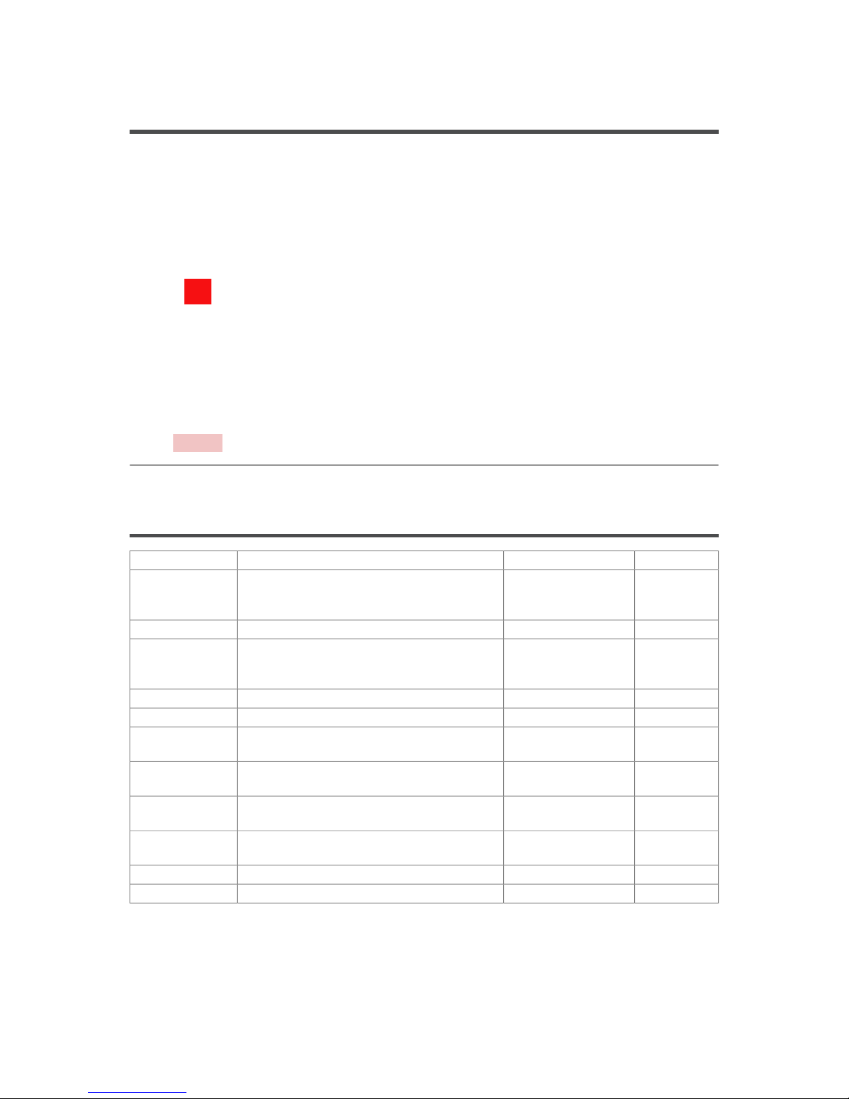
Symbols on the system
Warning
This symbol identifies situations where improper use of the machine can result in personal injury or
permanent/catastrophic damage to the machine.
This symbol also indicates to consult the operator manual in relation to this action.
Warning
This symbol indicates a danger caused by high voltage.
6
2
063.1 Service Guide