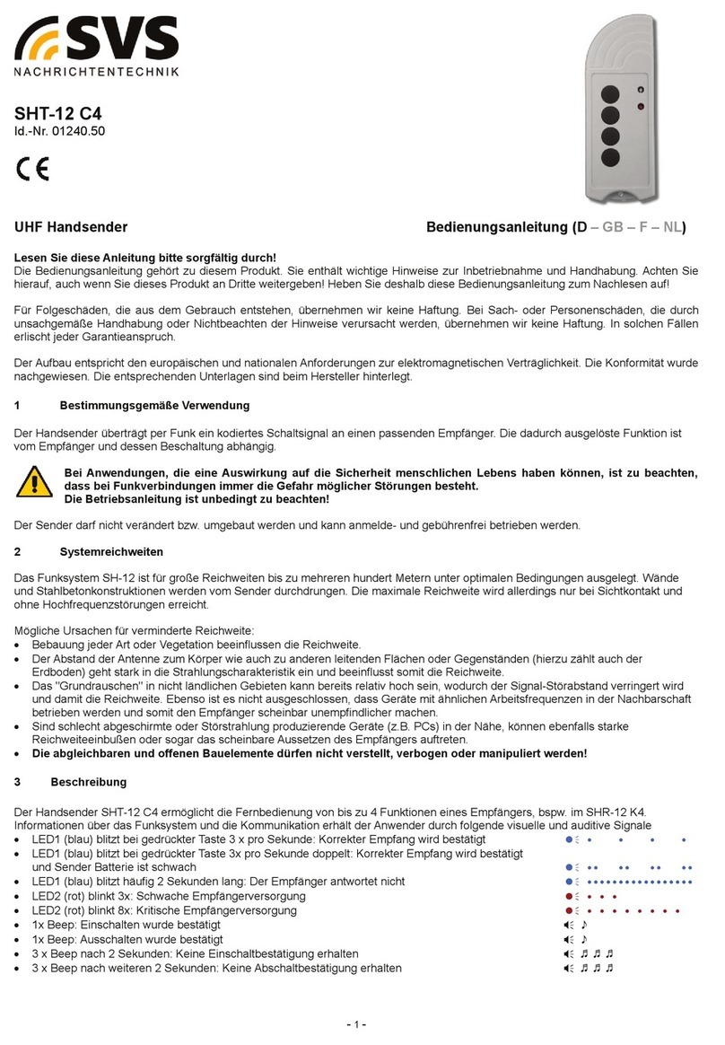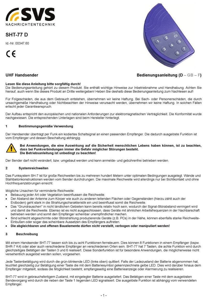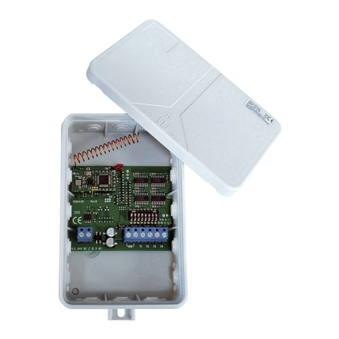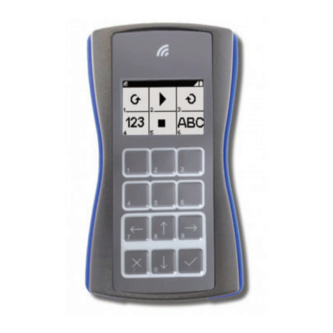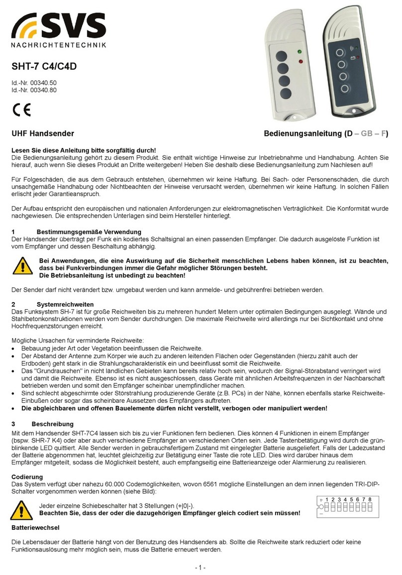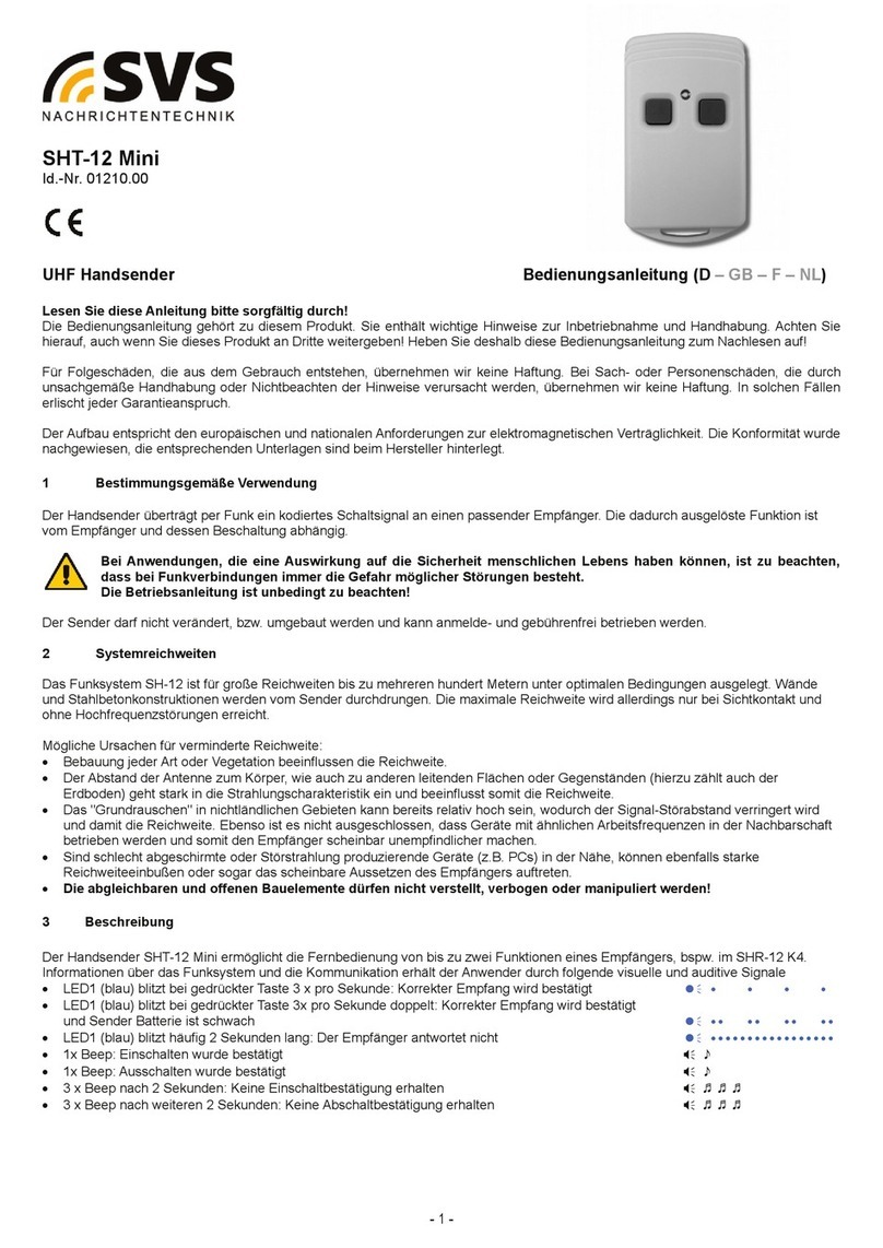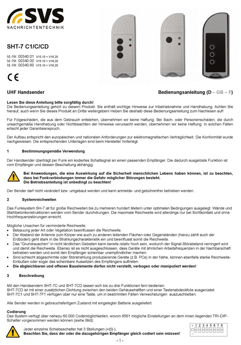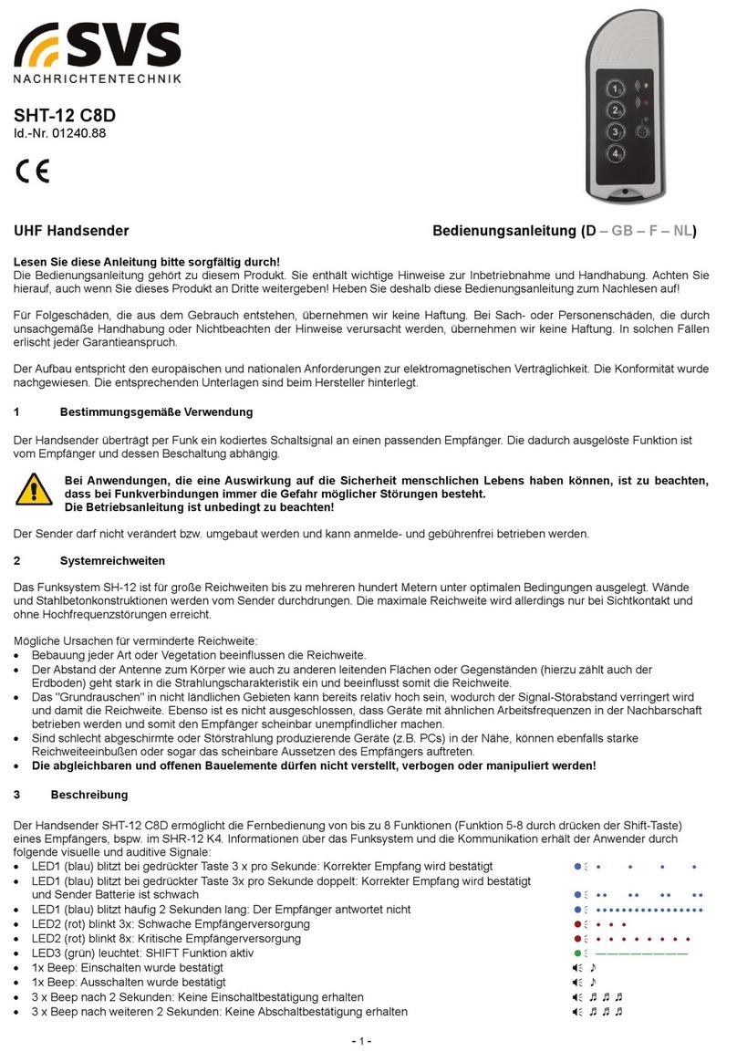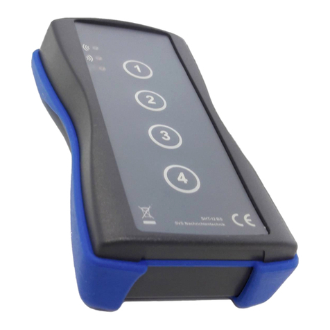
Batteriewechsel
Die Lebensdauer der Batterie h ngt von der Benutzung des Handsenders ab. Sollte die Reichweite stark reduziert oder keine
Funktionsauslösung mehr möglich sein, muss die Batterie erneuert werden.
Auf richtige Polarit t achten!
Verwenden Sie nur 12V-Alkaline-Batterien!
Die verbrauchte Batterie darf nicht über den Hausmüll entsorgt, sondern muss einer Altbatterie-Rücknahmestelle zugeführt
werden. utzen Sie hierfür öffentlich rechtliche Entsorgungsträger oder die beim Handel aufgestellten Behälter mit dem GRS-
Zeichen.
4 Technische Daten
Arbeitsfrequenz: 433,92 MHz Stromaufnahme: typ. 14 mA
Kodierungen: 6561 frei einstellbar Arbeitstemperatur: 0°C bis +65°C (Lagerung -40°C/+85°C)
Versorgung: 12 V - Alkaline – Batterie Geh useabmessung: 100 mm x 37 mm x 19 mm
UHF-Transmitter Operating Instructi ns (D – GB – F)
Please read carefully!
These operating instructions form an integral part of this product and contain important information on how to commission, install and
operate it. They must be taken into consideration and given to the end user or other third party when the installer hands over the
product. These operating instructions must be retained for future reference.
Damage resulting from abuse or misuse is not covered by warranty. The manufacturer accepts no warranty for consequential losses
that may result directly or indirectly from use of this equipment. Any changes or modifications not expressly approved by the party
responsible for compliance could void the user´s authority to operate the equipment.
The product meets the requirements of the current European and national guidelines for electromagnetic compatibility. Conformity has
been established and the relevant statements and documents have been deposited at the manufacturer.
1 M de f perati n
The transmitter is able to transmit coded signals to a matched receiver via radio transmission. The operation corresponding to these
signals depends on the receiver and its wiring.
It sh uld be n ted that f r applicati ns that c uld put human life at risk, by using radi c nnecti n there is always
present a p tential hazard due t extrane us disturbances.
The Operating Instructi ns need t be f ll wed at all times.
It is forbidden to modify or change component parts of these product.
2 System perating range
The system SH-7 is designed for a large operating range of many hundred meters. Walls including steel reinforced concrete can be
penetrated. The maximum range can be achieved under optimum conditions and by line-of-sight contact between transmitter and
receiver without disruption by external high frequency disturbances.
The following are possible causes that could reduce range of operation:
Obstructing buildings, vegetation or other factors will substantially reduce the operating range.
The distance between the antenna and the operator’s body or other conducting objects (e.g. Earth) may influence the working
range.
Background “electrical noise” could be relatively high so that the signal-to-noise-ratio may decease and therewith the operating
range. Also other devices, with similar operating frequency, operated in the neighbourhood of the receiver may reduce the
sensitivity.
Operating the receiver adjacent to badly shielded electronic components (e.g. PC’s) that can produce electromagnetic distortion,
may severely reduce the range of operation and could result in intermittent operation.
Adjustable and open components should not be adjusted or modified.
3 Descripti n
The transmitter SHT-7 C and SHT-7 CD are able to transmit up to 3 different signals to matched receivers. SHT-7 CD is manufactured
with a gasket between the pieces of case and an additional keyboard overlay. SHT-7 C1 and SHT-7 F1 act with only 1 Button, to avoid
faulty operation in dedicated applications.
Each transmitter is able to control a number of receivers.
C ding
To differentiate transmitter-/receiver-combinations, or if other systems are operated in the neighbourhood, the radio-code of the
transmitter may be selected out of 6561 options individually.
After releasing the screws on the rear side, the transmitter’s case can be split in two pieces. The Tri-DIP-
selection switch is located on the button-side of the board. Each of the switches has 3 setting positions (+|0|-).
- 2 -


