APsystems APstorage APbattery User manual

APbattery
USER MANUAL
Please read this manual carefully before installing the system
and carry out the installation procedures as per the instructions
Rev1.5 2023-11-29
© All Rights Reserved

APbattery USER MANUAL
1
Table of Contents
CHAPTER 1 INTRODUCTION .................................................................................................................. 2
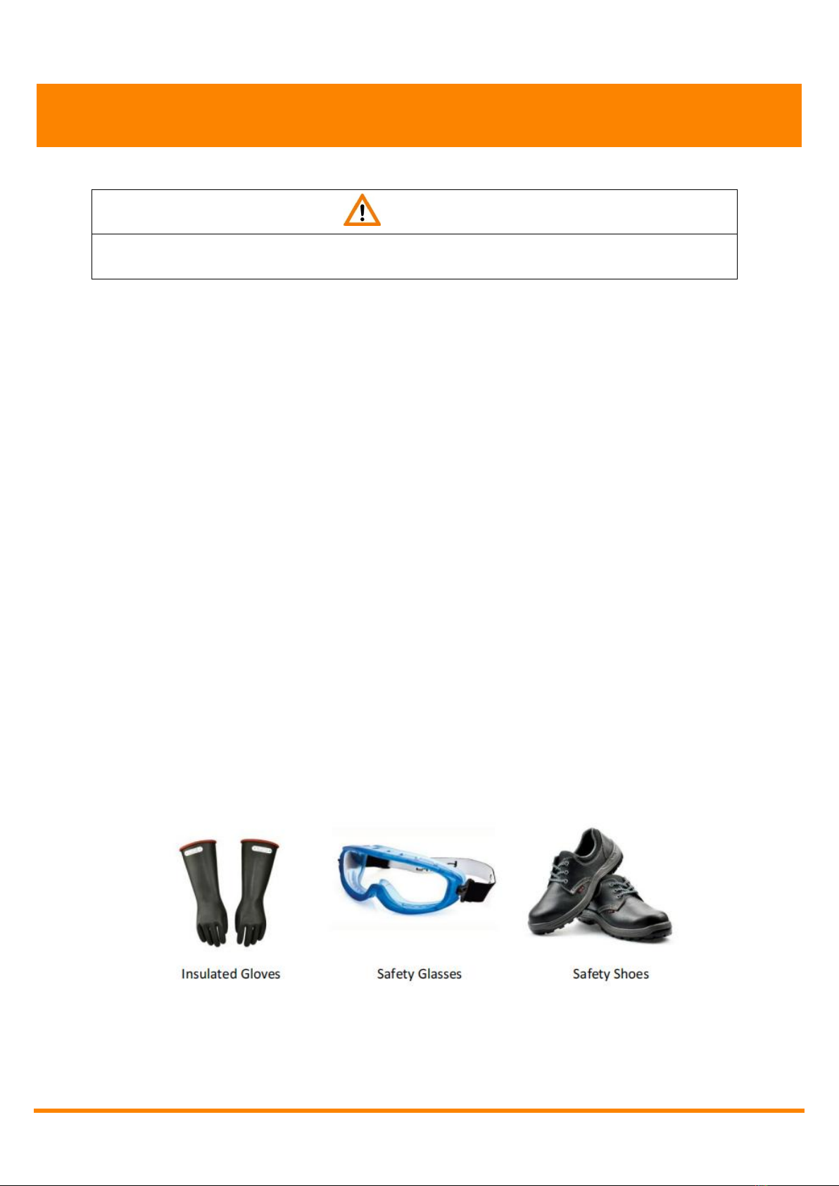
CHAPTER 2 PRECAUTIONS ....................................................................................................................4
CHAPTER 3 INSTALLATION CYCLE ....................................................................................................5
SECTION 3.1 Check kit components ............................................................................................ 6
SECTION 3.2 Read the instruction manual ................................................................................7
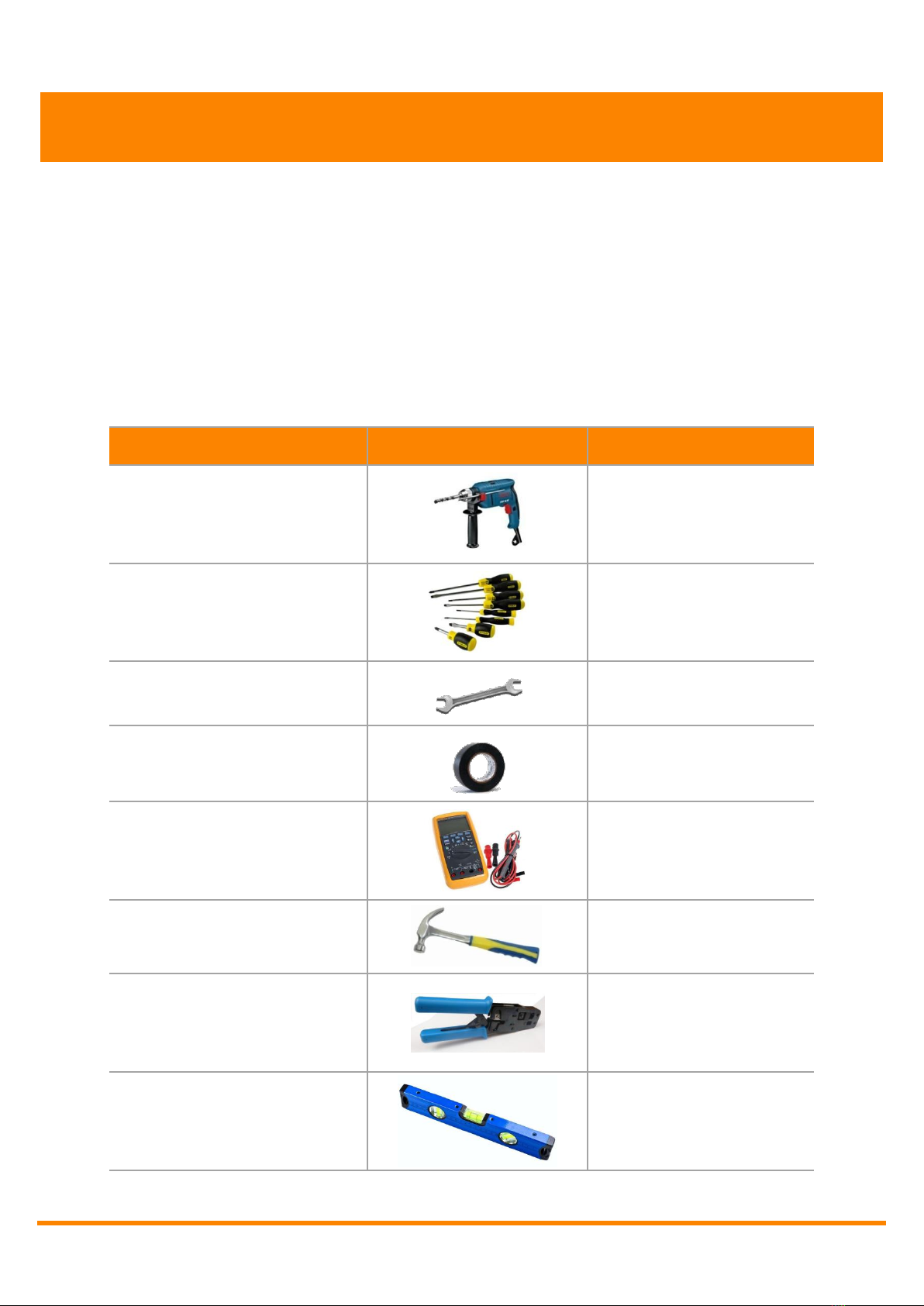
SECTION 3.3 Check installation tools ..........................................................................................7
SECTION 3.4 Risk assesment/compliance to standards ......................................................8
SECTION 3.5 Requirements for wall or support ......................................................................8
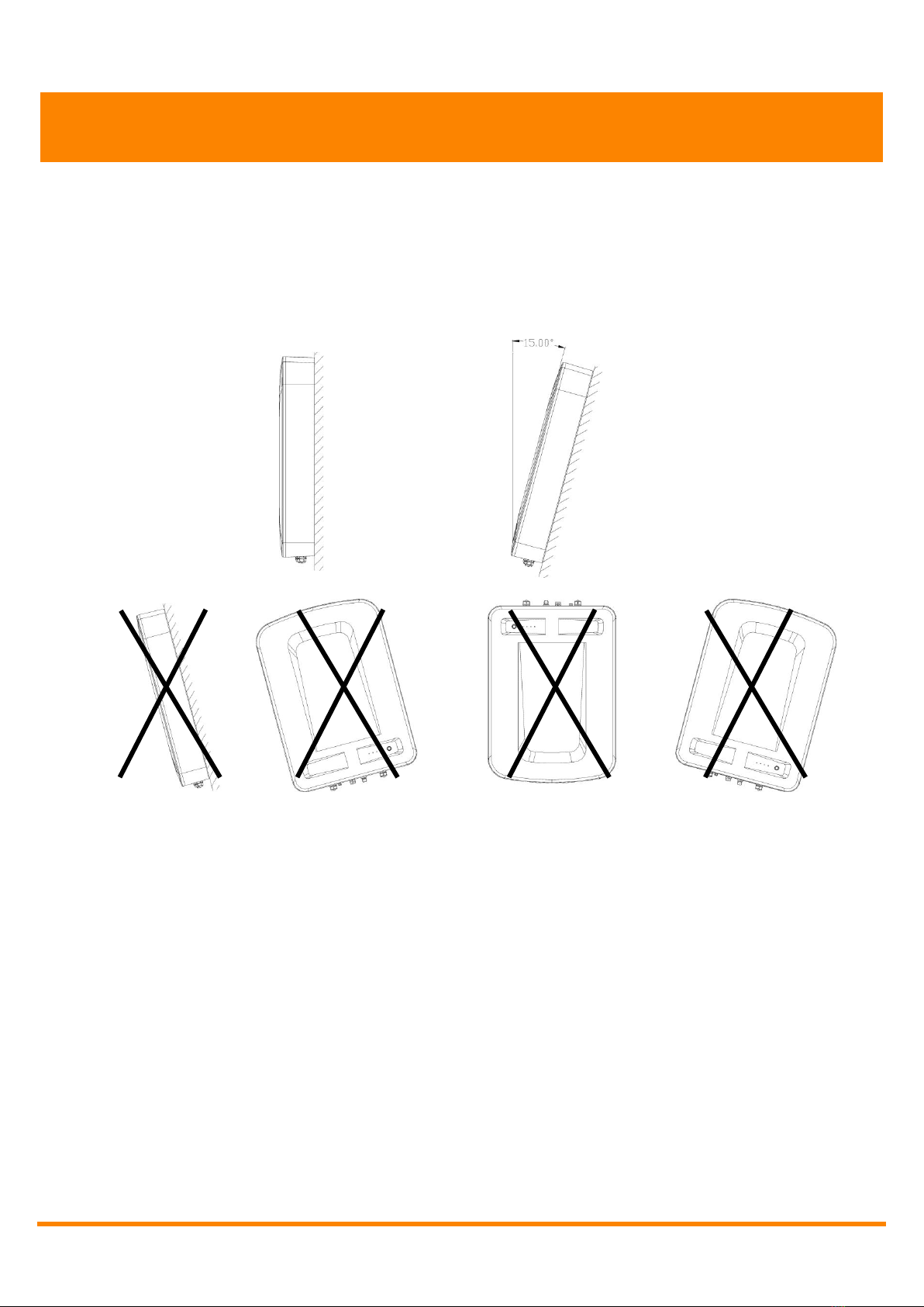
SECTION 3.6 Identify a suitable location for the APbattery ...............................................9
SECTION 3.7 Installation space planning ................................................................................. 10
CHAPTER 4 INSTALLATION .................................................................................................................11
SECTION 4.1 Installation for mounting plate .......................................................................... 11
SECTION 4.2 Installation for APbattery ................................................................................... 12
CHAPTER 5 WIRING ................................................................................................................................ 13
SECTION 5.1 Wiring in parallel ..................................................................................................... 16
SECTION 5.2 Wiring in parallel continued ............................................................................... 17
CHAPTER 6 Commissioning, operating,and maintenance .........................................................19
SECTION 6.1 Commissioning ........................................................................................................ 19
SECTION 6.2 Operating ..................................................................................................................20
SECTION 6.3 APbattery care ........................................................................................................21
SECTION 6.4 Maintenance ............................................................................................................ 21
CHAPTER 7 APPENDICES ..................................................................................................................... 22
SECTION 7.1 Troubleshooting ...................................................................................................... 22
SECTION 7.2 Emergency situation ............................................................................................. 22
SECTION 7.3 Specifications .......................................................................................................... 23
SECTION 7.4 Warranty claims and performance ..................................................................24

APbattery USER MANUAL
2
CHAPTER 1 INTRODUCTION
The purpose of this document is to provide information for the owner and
guidelines for the installer to help ensure that the APbattery energy storage system
is properly installed and operates to its designed potential.
This document sets out key criteria that describe a quality system and key design and
installation considerations that should be met in order to achieve this goal. This
document deals with APsystems energy storage system and is applicable for the
following APsystems energy storage system models: APbattery-48V/5.76kWh
These systems should be installed by competent installers who have completed an
Energy storage system installer training course. All specifications and descriptions
contained in this document are verified to be accurate at the time of printing.
Continuous improvement is a goal at APsystems and we reserve the right to make
product modifications at any time.
Thank you for choosing the APsystems APbattery, we are certain that with proper
operation and maintenance our system will provide you with clean renewable solar
electricity for many years.
This manual does not list all precautions needed for safe work. Any energy storage
system must comply with the Health and Safety Requirements and other relevant
standards and Codes of Practice within the country of installation. This manual
provides guidelines for installation but it does not guarantee the quality of
installation work. Please complete all work in a responsible and professional
manner.
All electrical work should be performed by a qualified electrician. It is the qualified
installers responsibility to ensure that the APbattery is suitable for your use to
deliver the best outcomes.

APbattery USER MANUAL
3
CHAPTER 1 INTRODUCTION
Items
Description
On/off button
Used as APbattery indicator and mode switching
APbattery terminals and
communication ports
Used to connect with PCS and operate the system
Safety switch
Used as the main circuit switch; Protect the circuit and avoid
unexpected issues occuring
Aluminum case
Used for natural cooling
Mounting plate
Used for fixing the APbattery on the wall
SOC Indicator
The four indicator lights equate to 25% charge each from left to right
Safety Valve
Valve for pressure release inside APbattery
Battery Terminals And Communication Ports
Safety Switch(ON/OFF)
Safety Valve

APbattery USER MANUAL
4
CHAPTER 2 PRECAUTIONS
WARNING
Failure to observe the precaution described in this section can cause serious injury to
persons or damage to property.
Observe the following precautions:
Risks of explosion
Do not subject the APbattery to strong impacts.
Do not crush or puncture the APbattery.
Do not dispose of the APbattery in a fire.
Risks of fire
Do not expose the APbattery to temperatures in excess of 50℃.
Do not place the APbattery near a heat source such as a fireplace.
Do not expose the APbattery to direct sunlight.
Do not allow the APbattery connectors to touch conductive objects such as wires.
Risks of electric shock
Do not disassemble the APbattery.
Do not touch the APbattery with wet hands.
Do not expose the APbattery to moisture or liquids.
Keep the APbattery away from children and animals.
Risks of damage to the APbattery
Do not allow the APbattery to come in contact with liquids.
Do not subject the APbattery to high pressures.
Do not place any objects on top of the APbattery.
It is recommended to wear the following safety gear when connecting the APbattery
with PCS.

APbattery USER MANUAL
5
CHAPTER 3 INSTALLATION CYCLE
The scope of this document includes the installation of the APbattery to a wall or
support structure, the connection of the D.C. wiring to the PCS. wiring required to
connect the PCS into the building’s electricity supply. A typical project cycle for a
APsystems APbattery is shown below. It shows consideration of the APbattery from the
start of the project through the stages of installation, commissioning, and finishing with
operation and maintenance considerations.
Installation Cycle
01
Check kit contents
02
Read instruction manual
03
Check installation tools
04
Risk assessment/Planning permission
05
Requirements for Wall or Support
06
Identify a suitable location for the APbattery
07
Installation space planning
08
Installation & Wiring

APbattery USER MANUAL
6
CHAPTER 3 INSTALLATION CYCLE
SECTION 3.1 Check kit components
Check kit contents against the included part list with component descriptions and
quantities. Ensure all components and quantities are present before starting the
installation project.
KITS
PICTURES
APbattery
×1
Mounting Plate
×1
Expansion screw
(M8*70)
×8
Ethernet cable
(Super Five Networks)
×1(self-provided)
Modular connector
(8P8C)
×2(self-provided)
Modular adapter
(3 WAYS)
(Multi-machine parallel connection is
applicable)(self-provided)
Modular adapter
(1WAY)
(Multi-machine parallel connection is
applicable)(self-provided)
Terminal blocks
×2
User manual
×1

APbattery USER MANUAL
7
CHAPTER 3 INSTALLATION CYCLE
SECTION 3.2 Read the instruction manual
All of the instructions should be thoroughly read and understood before attempting to
install, wire, operate and maintain the APbattery. Contact with electrically active parts
of the system such as terminals can result in burns, sparks, and lethal shock whether the
module is connected or disconnected. The installation of the APbattery should only be
performed by a qualified licensed professional, including, without limitation, licensed
contractors and licensed electricians. Please keep this manual for reference.
SECTION 3.3 Check installation tools
TOOLS
PICTURE
DESCRIPTION
Percussion drilling
Drill the wall
Screwdriver
Connect the wire to the
battery
Torque wrench
(M8)
Fix the expansion screws
Insulated rubber tape
To prevent leakage and
insulate wires
Multi-meter
Testing the connections
Claw hammer
Hit the screws
Crimping Pliers
Assemble the Ethernet
cable with Modular
connector to
RJ45(T568B)
Levelling instrument
To conduct the leveling
measurement

APbattery USER MANUAL
8
CHAPTER 3 INSTALLATION CYCLE
SECTION 3.4 Risk assesment/compliance to standards
The APbattery can power your home by combing with a PCS to store PV generated
electricity to create a solution for residential and light commercial properties.
Installation standards vary between countries and as such we recommend in all cases
that you check with your local standards authority before you commit to installing our
energy storage system. This document does not address health, safety, electrical or
building regulations matters, a site assessment and works method statement should be
completed prior to commencing the installation.
SECTION 3.5 Requirements for wall or support
WARNING
The APbattery should be installed to a wall capable of supporting its weight, interior walls are
preferred but where installation is on an exterior wall it should be protected from direct rain contact
and sunlight.
Local building regulations and standards should be observed to consider any fire ratings that may be
applicable.
Mounting position
The APbattery can be installed indoors or outdoors .Given the cooling and water-proof
factors of the machine, it is advisable to install the APbattery in a well ventilated and
sheltered place lest it is affected by direct sun radiation, rain, snow and others, so as to
lengthen the operation life of the PCS and the battery.

APbattery USER MANUAL
9
CHAPTER 3 INSTALLATION CYCLE
Mounting Angle
The APbattery should be installed vertically or tilted no more than 15°
Do not install the APbattery on a forward-leaning or horizontal plane.
Install the APbattery on a solid and ventilated surface.
SECTION 3.6 Identify a suitable location for the APbattery
Make sure the weight capacity of bracket location is greater than 80kg.
Make sure the location is not easily accessible by children and in an area free from
explosive or corrosive atmospheres.
For residential installations the energy storage is typically located in a secure
location shielded from direct sunlight and rain.
The APbattery must be mounted vertically on a wall or pole. Do not mount
horizontally as adequate heat dissipation cannot be ensured.
Make sure the APbattery is mounted in a location where the ambient temperature
range is -10 to +45℃. The APbattery may shut down automatically if it excessive
heat or cold temperatures.
A space of at least 100mm to 300mm around the enclosure guarantees optimum
ventilation.
√
√

APbattery USER MANUAL
10
CHAPTER 3 INSTALLATION CYCLE
The 1000mm lower clearance is only recommended where children could access
the APbattery and touch the heat sink/chassis.
Unless walls are properly insulated, avoid mounting the APbattery on any wall that
is directly exposed to the sun or a heat source such as a boiler room wall.
Only work on the APbattery when it is fully disconnected and observe the heat sink
temperature. Work should only be carried out by qualified person.
To minimize resistance and power loss, the customer should make sure to minimize
the wire lengths among the APbattery, the PCS and the main utility service panel.
Ensure the APbattery is mounted beside this cable entry to ensure successful
connection to the PCS.
SECTION 3.7 Installation space planning
300mm
1000mm
300mm
300mm

APbattery USER MANUAL
11
CHAPTER 4 INSTALLATION
SECTION 4.1 Installation for mounting plate
STEP
Description
Step1
Draw lines positioning the holder plate with ruler
on the wall
Step2
Drill the screw holes into the wall for
8×φ12×55mm
Step3
Tap the expansion bolts into the holes in the wall.
Tighten the hex nut with a wrench to fully
expand the expansion bolt sleeve.
Step4
Remove the hexagon nut on the expansion bolt,
hang the wall hanging plate on the expansion
screw, and fix it with the hexagon nut.

APbattery USER MANUAL
12
CHAPTER 4 INSTALLATION
SECTION 4.2 Installation for APbattery
WARNING
APbattery is heavy and challenging to lift, we recommend multiple persons to lift it.
We recommend to follow the schematic instruction to complete the installation.
Repeat the same installation process if you have multiple series or parallel installations of
the APbattery, until all the APbattery have been installed.
Take out the APbattery from the box
Hang the APbattery on the mounting plate,
observe the schematic instructions

APbattery USER MANUAL
13
STEP1
STEP2
STEP3
CHAPTER 5 WIRING
WARNING
The APbattery voltage between, the positive and negative terminals should be measured with
a multimeter before and after wiring (Ensure the APbattery is powered on). The initial voltage
should register within 48-54V DC. if the reading is outside this range then please call your
APsystems authorized reseller for advice.
It is recommended that the DC cable connection between the PCS and APbattery is kept to a
minimum to minimize line losses.
Negative
mounting plate
Positive
mounting
plate
Remove the positive
and negative mounting
plates at the bottom of
the battery
Thread the negative cable into the large
waterproof connector of the negative
mounting plate, and the communication
cable into the small waterproof
connector of the negative mounting
plate;
(Note: When using a single unit, you only
need to wear one communication cable,
and when using a parallel unit, you need
to wear two communication cables.)
Crimping the crystal head of the
communication cable;Crimping
the negative cable terminal.

APbattery USER MANUAL
14
STEP4
STEP6
STEP5
CHAPTER 5 WIRING
CHAPTER 5 WIRING
Connect the negative cable
to the terminal of the
battery negative interface;
Connect the communication
to the RJ45 communication
interface;
(Note: The communication
interface is in parallel and can
be connected to any
interface.)
The installation method of
positive cable is the same as that
of negative cable. (threading
before crimping the terminal)

APbattery USER MANUAL
15
STEP7
STEP8
STEP9
CHAPTER 5 WIRING
Connect the positive
cable to the terminal of
the positive interface of
the battery;
Adjust the tightness of the
waterproof connector, and
push the positive and
negative mounting plates
up to the proper position;
Press the positive and
negative mounting
plates and lock the
screws;

APbattery USER MANUAL
16
CHAPTER 5 WIRING
SECTION 5.1 Wiring in parallel
WARNING
The solid line in the figure represents the DC cable, and the dashed line represents the
communication cable.
Design specifications applicable for a maximum of 100 Amp charge/discharge PCS only.
DC cables need to be self-provided or purchased from the manufacturer.. Self-provided cable
is recommended to be 3AWG or 25mm2 and meet the requirements of local standards.
PCS
+ + - -
+-
PCS

APbattery USER MANUAL
17
CHAPTER 5 WIRING
SECTION 5.2 Wiring in parallel continued
BMS RJ45 definition
RJ45-PIN
1
2
3
4
5
6
7
8
BMS Port
WAKEUP-12V
WAK_GND
NC
CAN-H
CAN-L
NC
485-A
485-B
The CAN interface is used for communication between batteries in parallel, 485
interface to communicate with inverter.
Note that no WAKEUP function PIN1 / PIN2 must be disconnected.
Connection of Communication Cable
One APbattery connects to an RJ45 cable

APbattery USER MANUAL
18
CHAPTER 5 WIRING
Multiple batteries in parallel use RJ45 cables
Set the BMS control board address for parallel battery packs
If multiple batteries are used in parallel, you need to ask your dealer for a battery
address setting tool.
Debugging dip switch definition
DIP
Function
OFF
ON
remark
1
WAKEUP-12
V
disconnected
connected
PCS without WAKEUP function and must
be set to OFF.
2
WAK_GND
disconnected
connected
PCS without WAKEUP function and must
be set to OFF.
3
CAN
terminating
resistance
NULL
parallel
resistance
120Ω
Multiple batteries are used in parallel,
with the first battery and the last battery
set to ON.
4
485
terminating
resistance
NULL
parallel
resistance
120Ω
The default setting is OFF.

APbattery USER MANUAL
19
CHAPTER 6 Commissioning, operating,and maintenance
SECTION 6.1 Commissioning
STEP
Description
STEP 1
Turn on the safety switch
STEP 2
Hold the on/off button of the APbattery for over 3 seconds until the button light is in
a steady on state Ensure all the APbattery are powered on.
STEP 3
Ensure the PCS and APbattery are connect successfully.
STEP 4
An error message will appear on the PCS screen if the connection failed.
(Refer to the troubleshooting section to solve the problem)
STEP 5
If the problem cannot be solved please contact the after sales service of APbattery
and PCS company.
Table of contents