manuals.online logo
Brands
  1. Home
  2. •
  3. Brands
  4. •
  5. Sun Fun Kits
  6. •
  7. Batteries Pack
  8. •
  9. Sun Fun Kits V3.5 User manual

Sun Fun Kits V3.5 User manual

Sun Fun Kits V3.5 Assembly Manual
Revision 1.2
Before you Begin:
Thank you for purchasing your Sun Fun Kits V3.5 DIY battery kit, the diy battery kits makes
assembling your battery quick and easy and only requires basic tools and hardware. We
recommend having a basic understanding of DC wiring in order to assemble your battery pack.
You will also need the following tools:
● Hex driver set: 3mm, 4mm, 5mm, and 8mm
● Insulated drives for securing bolts
● Thread locking compound (such as blue Loctite)
● Kapton tape 1” to 2” in width
● Double Sided Sticky tape
● Velcro style loop
● DC Voltmeter
● DC Power Supply that is able to charge up battery cells (3.65 volts, 20 Amps)
Optional:
● Electrical Safe Silicone sealant (for those looking to make a water resistant battery)
● Hot glue gun (if you wish to secure wires using this method)
Page: 2 V3.5 Manual - Revision 1.2
Video Manual (V3 Manual):
If you are more of a visual learner, you can view the build process on our official youtube
channel: https://youtu.be/tWm65Pu0GuI
Preparing your battery cells:
Sun Fun Kits DIY battery kits support various prismatic cells, in this manual we will be using the
EVE LF304 type, however the process is the same for other manufacturers such as CATL,
REPT, Ganfeng and more, the V3 Kit includes spacers and other items to ensure maximum
compatibility for cells in this class (270-320 AH)
Certified Automotive Grade Cells generally do not require balancing; however, you may choose
to balance your cells, we have a video explaining this process.
This process is explained in this tutorial video:
Page: 3 V3.5 Manual - Revision 1.2
https://www.youtube.com/watch?v=JGbZozzCYvM
NOTE: if you are using an RTB (ready to build kit) the active balancer will assist in top balancing
your cells, simply assemble your pack, charge the battery at 5-20 amps and within 1-2 hours
your cells should be even balanced. Again, certified cells that are included with your RTB kit will
balance very quickly and the active balancer is included simply to assist balancing during high
amperage charging (over 80 amps).
Assembling your battery cells:
Starting with version 3.5 we are now including different cell shims or spacers, this allows users
to have a nice tight fit while also adding a third layer of insulation between cells. Version 3.5
includes 1 set of 1.5mm and 1.0mm shims (3 pieces each). The shims should be placed
between the inner cells and most installs will use about 3 shims. For Sun Fun Kits certified cells
(280K and LF304) you should be able to use 3 x 1.5mm shims to complete the install and have
a nice tight fit.
Page: 4 V3.5 Manual - Revision 1.2
If you find difficulty installing the 1.5mm shims you may go down to 1.0 MM shims, you can mix
and match the 1.0 and 1.5mm shims as needed to suit your install preference.
Basic Heating Element Setup:
Version 3.5’s basic heating element includes dual heating pads on the inside walls of your kit.
This provides good heating and will raise the inside temperature of your case evenly. This
method is quite easy to install and is the only method that should be used if you are using grade
B cells or swollen cells as it provides the most amount of spacing for the cells.
Begin by placing your cells in a series configuration with the left side of the battery having the
positive terminal on the lower left and the negative terminal on the lower right.
Page: 5 V3.5 Manual - Revision 1.2
Note: You will want to have the textured side of the shim facing the cell you installed, with the
smooth side facing the empty space. This will ensure the shim stays in place while you install
cells.
Page: 6 V3.5 Manual - Revision 1.2
For the last cell make sure the shim’s smooth side is facing the opening, in this case we will be
inserting cell no.2 and both sides of the shims will be smooth for an easy install.
Note: you may find some resistance installing your cells, this is because the EPE foam exerts
pressure on the cells to keep them in place; this is why we recommend adding the left most and
right most cells first and then adding the remaining 2 inner cells in the end as shown in the
illustrations above.
PLEASE MAKE SURE TO PLACE CELLS CORRECTLY IN THE ORDER ABOVE.
V3.5 kits support various cells and depending on your cell height you may or may not need cell
spacers. For LF280K and LF304 cells sold by Sun Fun Kits, you will use the 4mm spacer on top
of the aluminum braces to raise the height of the support so that it matches the cell. If you are
using EVE LF280N or other cells that are 200mm tall you can skip this step as the aluminum
bracket matches the height of your cells.
Page: 7 V3.5 Manual - Revision 1.2
The heated kits will provide additional resistance to cells when they are being installed,
however, there is still sufficient space to insert the cells. It is recommended that you do not
install fully charged cells as they will make the process challenging.
Page: 8 V3.5 Manual - Revision 1.2
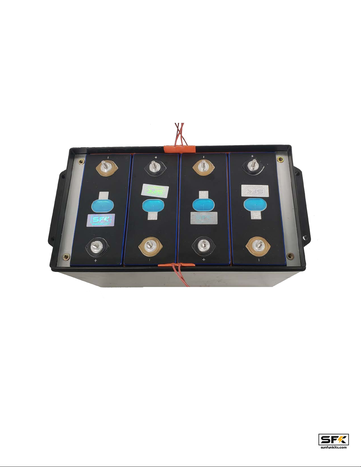
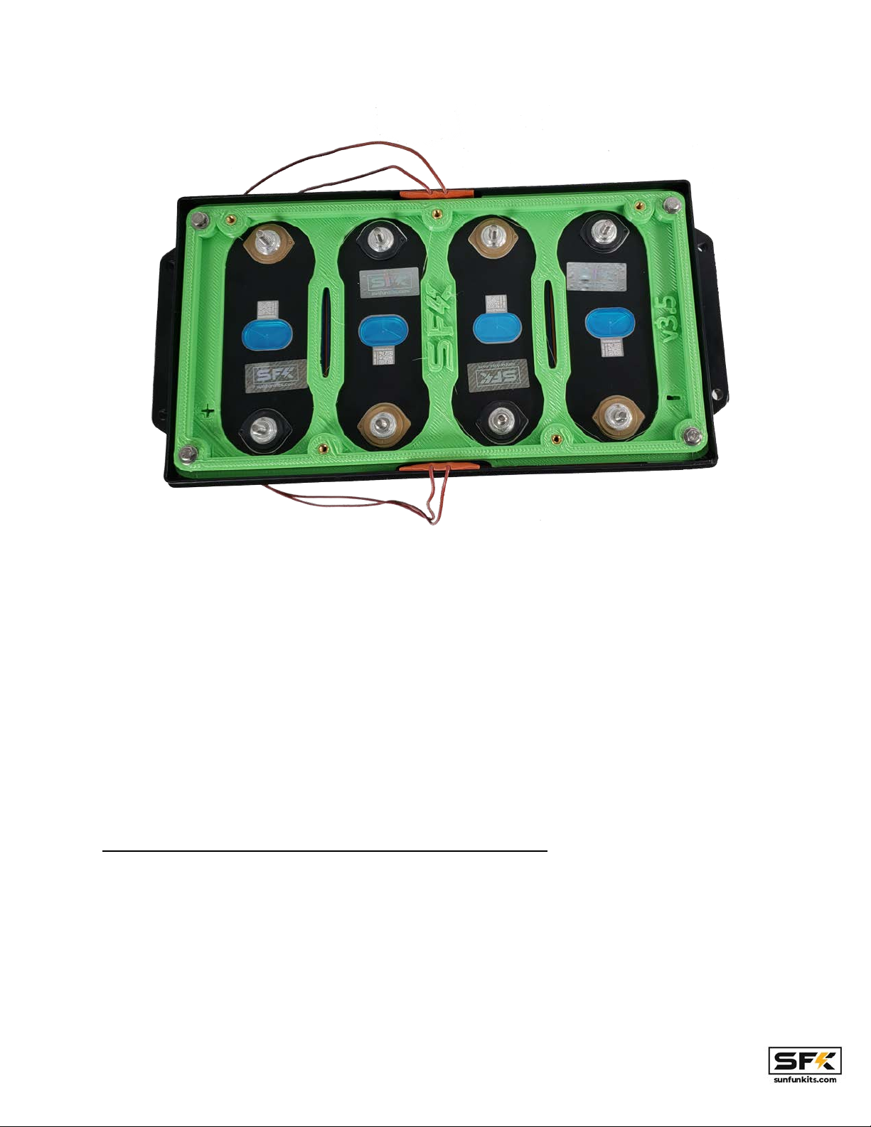
Once your cells are in the correct position; it is now time to install your bottom bracket. With our
v3 kits we have made our cell bracket universal and it should fit virtually all cells in the 270-320
AH class.
Install the bottom bracket with the M5 bolts and washers, you can use power tools to assist in
this step. NOTE: Ensure the negative and positive signs on the plate match your cells.
Version 3.5 has a notch cut on the upper and lower middle to allow the wires from the rubber
heating elements which provide a channel for the wires into the main battery assembly.
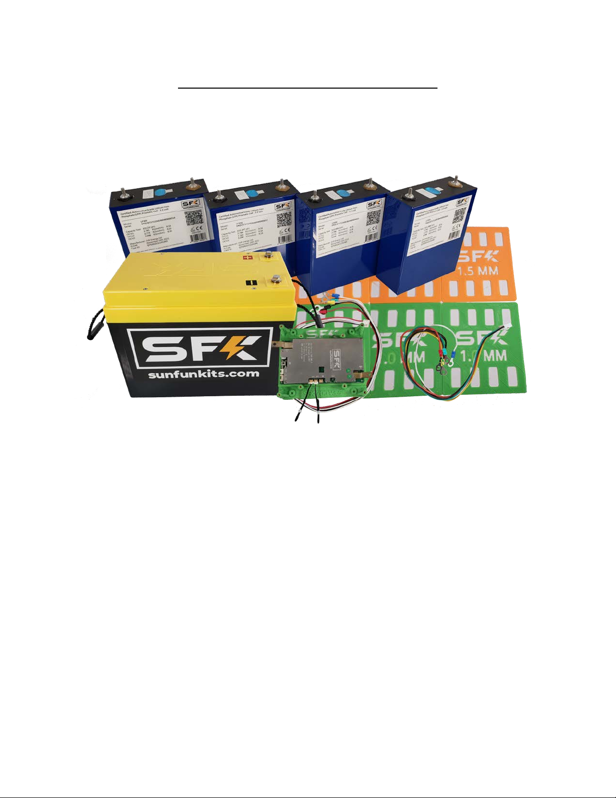
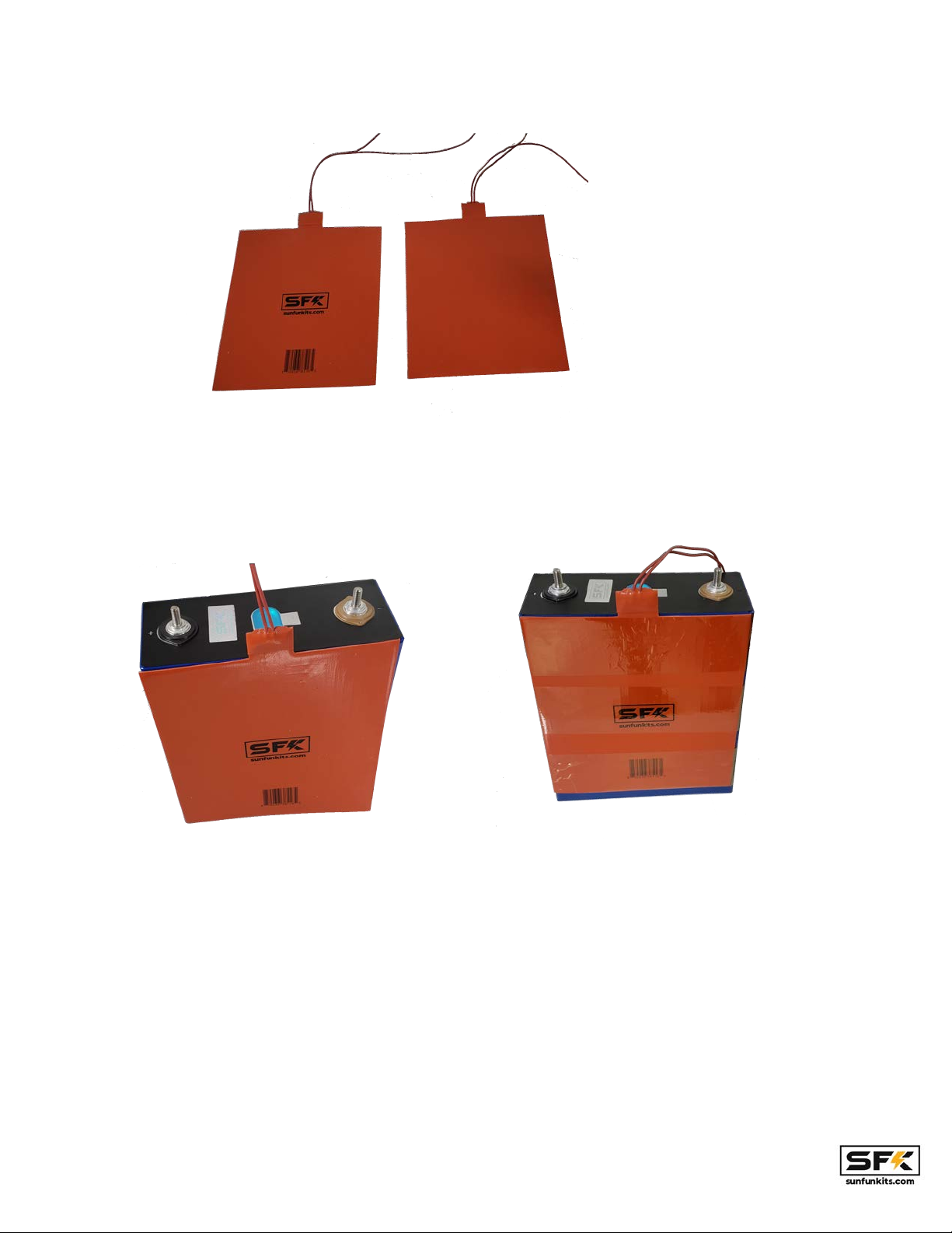
Setting up heating using heated cell-separators (advanced):
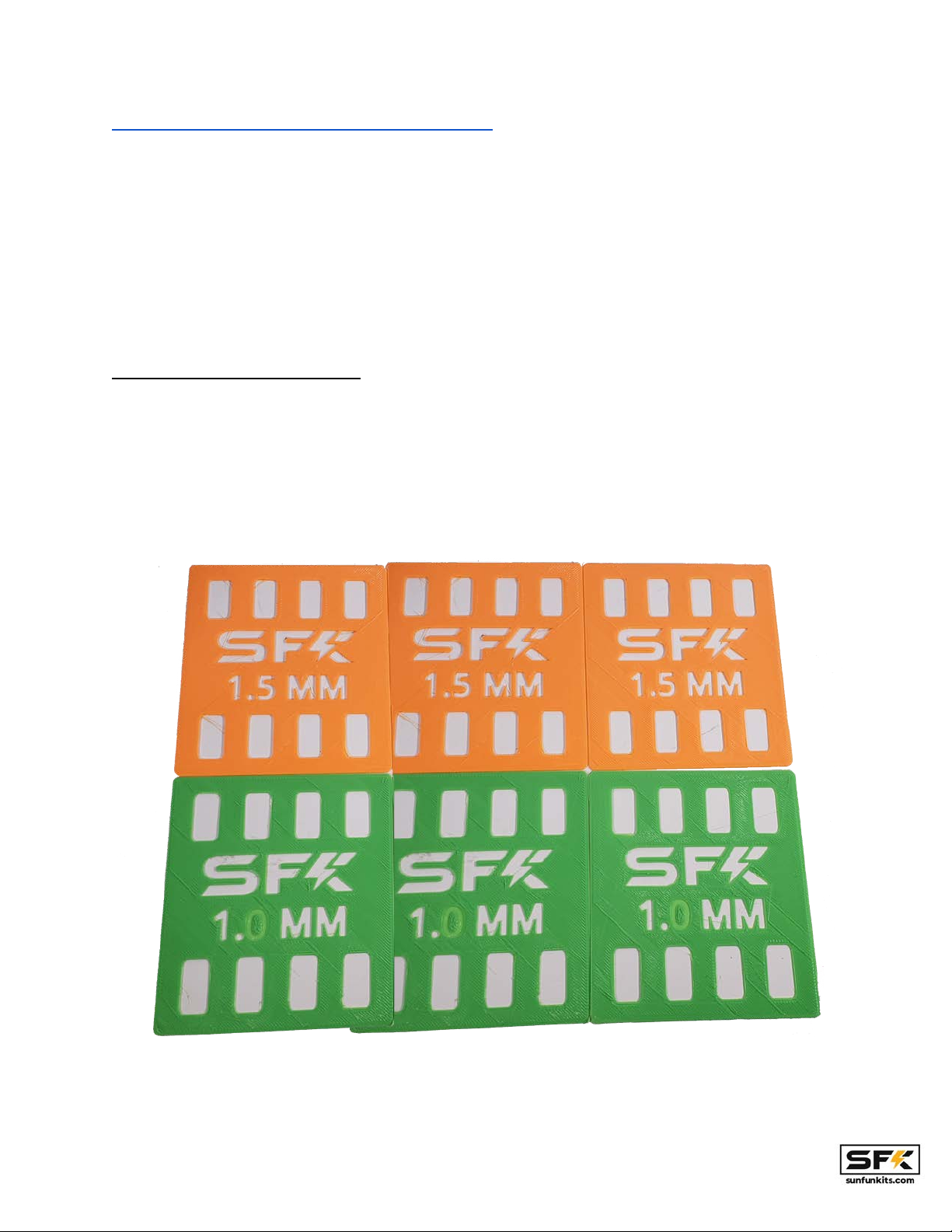
The cell separator option is the more advanced heating option available in version 3.5 kits, this
allows 2 cells to be heated by a single silicon rubber heating element; 2 elements in total are
able to heat all 4 cells. The direct contact nature of this option means that the cells will heat up
faster so there is a potential of having a bigger delta in temperature between the cells and the
rest of the case. However, this method will provide for superior cell heating.
Page: 9 V3.5 Manual - Revision 1.2
Locate the 2 silicone rubber heating elements and attach them to your cells using KAPTON
TAPE or PET/Polyester high temp Tape. DO NOT USE SCOTCH™ or other forms of plastic
tape, KAPTON (PET or Polyester BASED) is required to handle the heat being generated by the
silicone pads.
Once attached you will be able to place this into your battery case (note in this case there are
no heating elements on the sides of the case walls).
As with the non-heated kits, place the leftmost and rightmost cell first, ensuring they have the
correct polarity before installing.
Page: 10 V3.5 Manual - Revision 1.2
For the inner 2 cells you will use a shim for one of the cells to provide the final cell separator for
the kit, you can select from either the 1.0m or the 1.5mm shim depending on how tight you want
your install to be (the tighter the better for most installations).
The textured side of the shim should be facing the cell while the smooth side should be
exposed.
Page: 11 V3.5 Manual - Revision 1.2
You will use the same method to install the final cell as in the non-heated kits and work the cell
in. Some resistance is normal as this will ensure a tight fit and make sure your cells do not move
around.
After completing you will 2 heating pads and 1 shim, now you can place the cells spacers
(shown above as the green pieces that sit on top of the aluminum brackets) and proceed with
mounting the V3.5 main plate (note the cell spacers are needed for cells that are 204mm or
taller, if you have 200mm tall cells you do no need to add the cell spacers on
Route the heated cell-separators through the dedicated slots on the v3.5 kit.
Page: 12 V3.5 Manual - Revision 1.2
You will now need to crimp connectors to the wires of your heating pads, to do this you will need
to crimp 1 wire from each pad together for the yellow terminal (this will go to the positive lug on
the case) and 1 wire from each pad to the black terminal (this will go to the heater port on the
BMS). DO NOT CRIMP BOTH wires of the same pad together it will not complete the
circuit. Which wires you chose does not matter as long as the wires being crimped are not from
the same pad.
Page: 13 V3.5 Manual - Revision 1.2
Setting Up Electronics & Cell wiring:
This step involves wiring up your cells, you will need a BMS system and optionally a
supplementary balancing device to complete this step. You will also need to have the
appropriate wiring done to complete the electrical setup. If you are using our SFK-200V2 4s
Bms, all wiring and prep has been done for you; simply bolt onto your components; no crimping
or cutting is necessary.
The V3.5 kit system supports various BMS devices from manufacturers such as JBD (SFK
Series), Daly, Ant, QUCC, and more. New device support is being added constantly; if you need
a specific mounting plate made, simply contact Sun Fun Kits support at [email protected]
Page: 14 V3.5 Manual - Revision 1.2
Begin by aligning your buss bars as follows:
Page: 15 V3.5 Manual - Revision 1.2
Now you will add your series terminals and BMS balancing/monitoring wires as well as the
active balancer wires (NOTE the initial negative post; and the final positive post are shared
between both the active balancer & BMS, all other posts may be separate for each cell)
USE EXTREME CAUTION! THE BLUE WIRE SHOULD NOT TOUCH THE POSITIVE
TERMINAL OF THE FIRST CELL OR IT WILL ARC AND DESTROY THE CELL. You should
consider covering this terminal with kapton tape or other insulating material to ensure
that it can not short circuit the first cell.
NOTE: be sure to use the included washers for the BMS and Active balancer terminals. A
washer should be placed above each bus bar, and optionally above it. For version 3.5 we are
now including M8 Nylon Lock nuts as they provide excellent anti-vibration capabilities without
needing thread locking compound.
Please note your BMS wires should be routed to the positive terminal and the active balancer
wires should be routed to the negative terminal.
Page: 16 V3.5 Manual - Revision 1.2
Your cells should come with the bus bar, terminal studs or welded terminals. Tidy up your install
using electrical tape, zip ties, or velcro strips. Setup the wiring schematic as follows:
black wire = cell 1 negative (0.00 Volts)
1st white wire (green lug) = cell 1 positive / cell 2 negative bus bar (either post may be used)
(3.3 Volts)
2nd white wire (yellow lug)= cell 2 positive / cell 3 negative bus bar (either post may be used)
(6.6 Volts)
3rd white wire (blue lug) = cell 3 positive / cell 4 negative bus bar (either post may be used) (9.9
Volts)
red wire = cell 4 positive (13.2 Volts)
*The 1st white wire is the wire that is right next to the black wire, the subsequent wires will be
white wire 2, and white wire 3.
The active balancer should be wired:
black wire = cell 1 negative (0.00 Volts)
green wire = cell 1 positive / cell 2 negative bus bar (either post may be used) (3.3 Volts)
yellow wire = cell 2 positive / cell 3 negative bus bar (either post may be used) (6.6 Volts)
white wire = cell 3 positive / cell 4 negative bus bar (either post may be used) (9.9 Volts)
red wire = cell 4 positive (13.2 Volts)
You will need to ensure a tight fit, take care not to strip your battery terminals, if you are using a
torque wrench you will want to tighten down to 4-6 NM. WARNING! Loose terminals will cause
the cells & batteries to fail.
Page: 17 V3.5 Manual - Revision 1.2
With version 3.5 we have color coded the BMS wires to match the active balancer to assist in
installs, you can use this combination to ensure you have matching connections.
Your voltages should read:
3.3, 6.6, 9.9,13.2 (Nominal Voltage).
If you are using a supplementary balance, you should install this as well, you will need to share
the final negative and positive terminals of the battery for the bms and the supplementary
balancer.. Make sure the wired main lugs are the ones that touch the cell terminal and only
stack the other bms and active balancer rings on top.
Page: 18 V3.5 Manual - Revision 1.2
All V3.5 RTB kits include the active balancer, and we highly recommend using it as it
reduces the balancing stress on your BMS and is able to balance out cells significantly
faster during charging.
Once you have verified the wiring has been installed correctly, you can now begin by attaching
the top plate & your BMS.
Installing riser and BMS mounting plates:
After you have verified that your cells are mounted correctly AND VERIFIED they have correct
voltage readings, you can now begin mounting the BMS and other related electronics. Being by
mounting the riser plate by first inserting the active balancer connector into the balancing unit
and then rotate it so that it matches the mounting holes on the main kit plate:
Page: 19 V3.5 Manual - Revision 1.2
Secure the riser plate using the 3 countersunk M4 screws. We recommend only using hand
tools for this process (despite the youtube videos where the installer and author of this manual
uses an impact hammer… ).
The heated kits will power the silicon rubber heating elements either form dedicated ports on the
BMS. Starting with Version 3.5 we will be exclusively using BMS based heating as based on
your user feedback this is the preferred method most users want. The SFK-200 V2 BMS is an
excellent choice for this as it has a dedicated heating port that is activated during low
temperature charging.
Page: 20 V3.5 Manual - Revision 1.2

Other Sun Fun Kits Batteries Pack manuals

Sun Fun Kits V4 User manual

Sun Fun Kits

Sun Fun Kits V4 User manual

Sun Fun Kits V3 User manual

Sun Fun Kits

Sun Fun Kits V3 User manual

Sun Fun Kits LF280K User manual

Sun Fun Kits

Sun Fun Kits LF280K User manual

Sun Fun Kits V1 User manual

Sun Fun Kits

Sun Fun Kits V1 User manual

Popular Batteries Pack manuals by other brands

Lithionics Battery NeverDie-PSS-SOC Wiring diagram

Lithionics Battery

Lithionics Battery NeverDie-PSS-SOC Wiring diagram

Ryobi P104 manual

Ryobi

Ryobi P104 manual

Anker SOLIX BP3800 user guide

Anker

Anker SOLIX BP3800 user guide

xtorm XE105 ESSENTIAL manual

xtorm

xtorm XE105 ESSENTIAL manual

Panasonic FZ-VZSU94 series operating instructions

Panasonic

Panasonic FZ-VZSU94 series operating instructions

RIGIBORE ActiveEdge AE-BPK02 Replacement manual

RIGIBORE

RIGIBORE ActiveEdge AE-BPK02 Replacement manual

XD COLLECTION P322.61 Series manual

XD COLLECTION

XD COLLECTION P322.61 Series manual

AIMS Power LiFePO4 LFP12V50B instruction manual

AIMS Power

AIMS Power LiFePO4 LFP12V50B instruction manual

Atronix AX2.88kWhBM Installation and operation manual

Atronix

Atronix AX2.88kWhBM Installation and operation manual

Tripp Lite BP480V140 Specifications

Tripp Lite

Tripp Lite BP480V140 Specifications

Tripp Lite SmartPro BP48V60RT3U owner's manual

Tripp Lite

Tripp Lite SmartPro BP48V60RT3U owner's manual

Power-Tronics ABF10 manual

Power-Tronics

Power-Tronics ABF10 manual

SUNGOLD POWER SG48100M user manual

SUNGOLD POWER

SUNGOLD POWER SG48100M user manual

Sofar solar BTS Series user manual

Sofar solar

Sofar solar BTS Series user manual

Tracer BP2564 operating instructions

Tracer

Tracer BP2564 operating instructions

Tripp Lite BP24V9T owner's manual

Tripp Lite

Tripp Lite BP24V9T owner's manual

Tripp Lite BP480V09 owner's manual

Tripp Lite

Tripp Lite BP480V09 owner's manual

LG Chem RESU7H StorEdge installation manual

LG Chem

LG Chem RESU7H StorEdge installation manual

manuals.online logo
manuals.online logoBrands
  • About & Mission
  • Contact us
  • Privacy Policy
  • Terms and Conditions

Copyright 2025 Manuals.Online. All Rights Reserved.