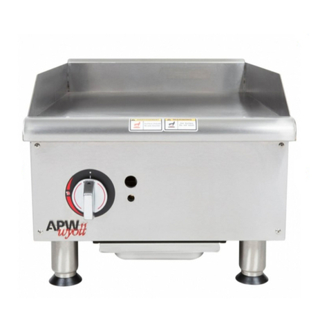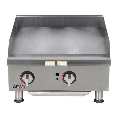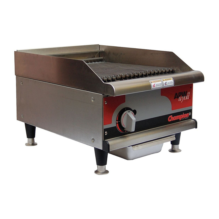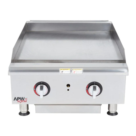
Specifications And Dimensions:
Model Width Depth Height No. of kW Per Total
in. (mm) in. (mm) in. (mm) Elements Element kW
EGD-48 49.0/125 29.5/75 0.31/0.8 82.7 21.6
EGD-72 72.0/191 29.5/75 0.31/0.8 12 2.7 32.4
EGD-72 72.0/191 32.5/83 0.31/0.8 12 2.7 32.4
Double Trough
Griddle Surface Dimensions: Model Width in./cm Depth in./cm
EGD-48 46.5/119 23.94/61
EGD-72 69.5/177 23.94/61
General Installation Instructions:
Caution: DO NOT use an open flame to check for leaks. Check all gas piping for leaks with a soap and water solution
before operating unit.
NOTICE THE UNIT, WHEN INSTALLED, MUST BE ELECTRICALLY GROUNDED IN ACCORDANCE WITH LOCAL CODES, OR IN THE
ABSENCE OF LOCAL CODES, WITH THE NATIONAL ELECTRICAL CODE, ANSI/NFPA 70, LATEST EDITION.
CANADIAN INSTALLATION MUST COMPLY WITH THE CANADIAN ELECTRICAL CODE, CSA C22.2, AS APPLICABLE.
NOTICE Local codes regarding installation vary greatly from one area to another. The National Fire Protection Association, Inc., states in its
NFPA 96 latest edition that local codes are "authority having jurisdiction" when it comes to requirements for installation of equipment. There-
fore, installations should comply with all Local codes.
General Installation Instructions:
With all the large holes cut out, the smaller control panels drilled, and the stiffening angle welded into place, the
fixture is now ready to receive the griddle.
1. The manufacturer furnishes a gasket or seal that must be placed around the perimeter of the hole in the top as
shown in Fig. 4. This gasket may be temporarily held in place with tape. Do not place the staple securing the
gasket ends on or near a corner.
2. A number of clamps, such as the one shown in Fig. 4, appear at intervals along the perimeter. Pull clamps
outward so the griddle frame clears them when it is dropped into place.
3. Drop the griddle into position by lowering it into the fixture top hole. Make sure the thermostat capillaries are
not kinked or pinched when setting the griddle in place. With the griddle in place, the gasket or seal becomes
compressed. See Fig. 5.
4. Slide the clamp inward so it engages the upper part of the protruding angle from the griddle frame. See Fig. 6.
Slide the clamp sideways so the notch on it locks against the reinforcement angle. This prevents the clamp
from sliding out.
5. Tighten the clamp screws against the angle as shown in Figure 6. This tightening forces the clamps to press
down on the griddle body frame extension. The griddle top is now drawn close to the fixture top, compressing
the gasket and forming an effective grease guard. Tighten at least one screw on each side before tightening
all screws. Do not exceed 60 in/lb torque when tightening bolts.
6. Slide the tray slide (grease drawer receptacle) through the cutout hole on the apron or front of the fixture,
resting it on the two “U” braces.
7. Mount the thermostats to the control panel and make the pilot light connections per the accompanying wire
diagram. Before making any electrical connections, check nameplate voltage (located on tray slide under
grease drawer) to ensure it matches voltage being applied.
8. Set the control panel in place and screw it to the apron using the ½-inch long thread forming screws.
9. Pull the tray slide against the back of the control panel and secure it with the appropriate screws.
10. Slide the grease drawer into place.
4
