Copyright © 2021 Aqua Creek Products All Rights Reserved Revised 5/28/21
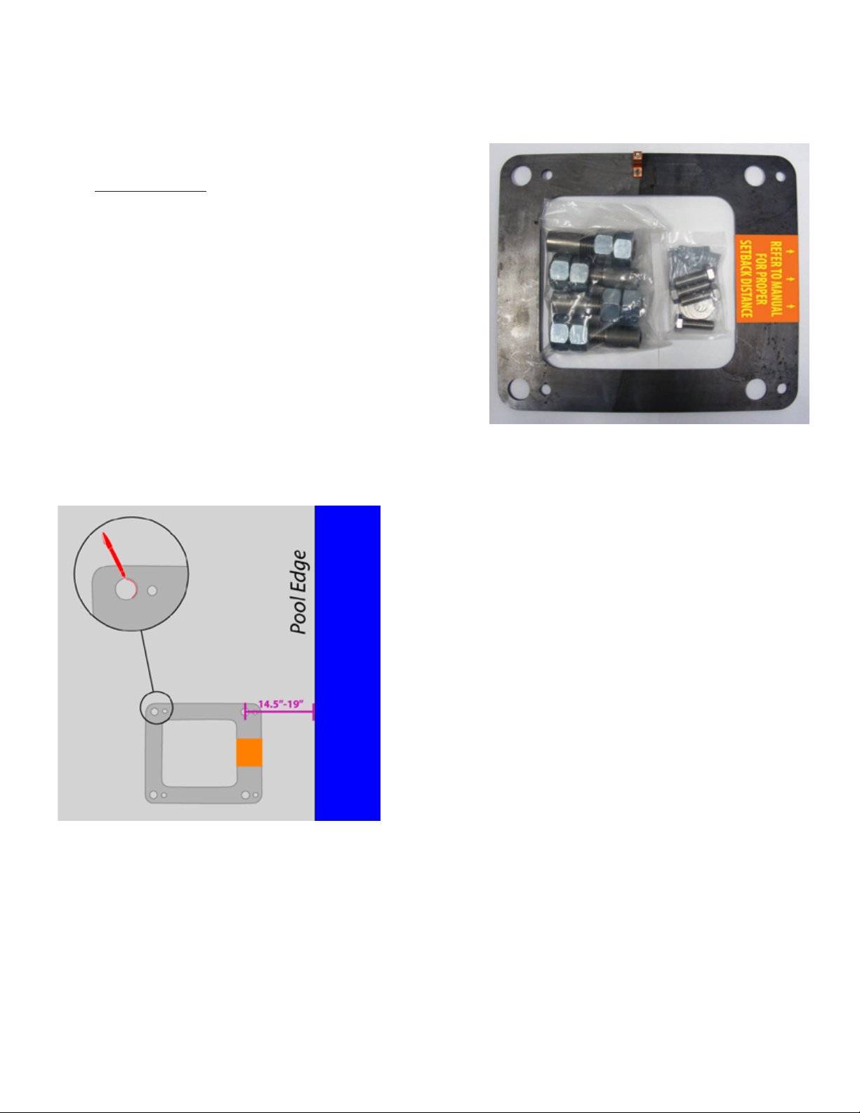
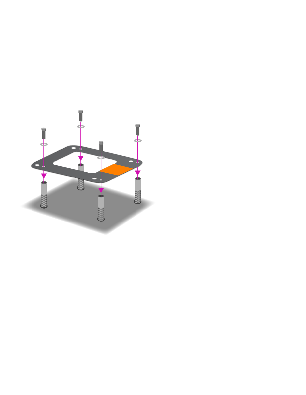
1. Remove 1 nut from each anchor insert. Place the anchor inserts through the larger hole
of the anchor jig plate. Thread the removed nuts back onto the anchor inserts. The anchor
plate should be sandwiched between the two nuts on each anchor insert.
SEE FIGURE A, PAGE 7
2. Install rebar in the open area of the deck.
SEE FIGURE B, PAGE 7
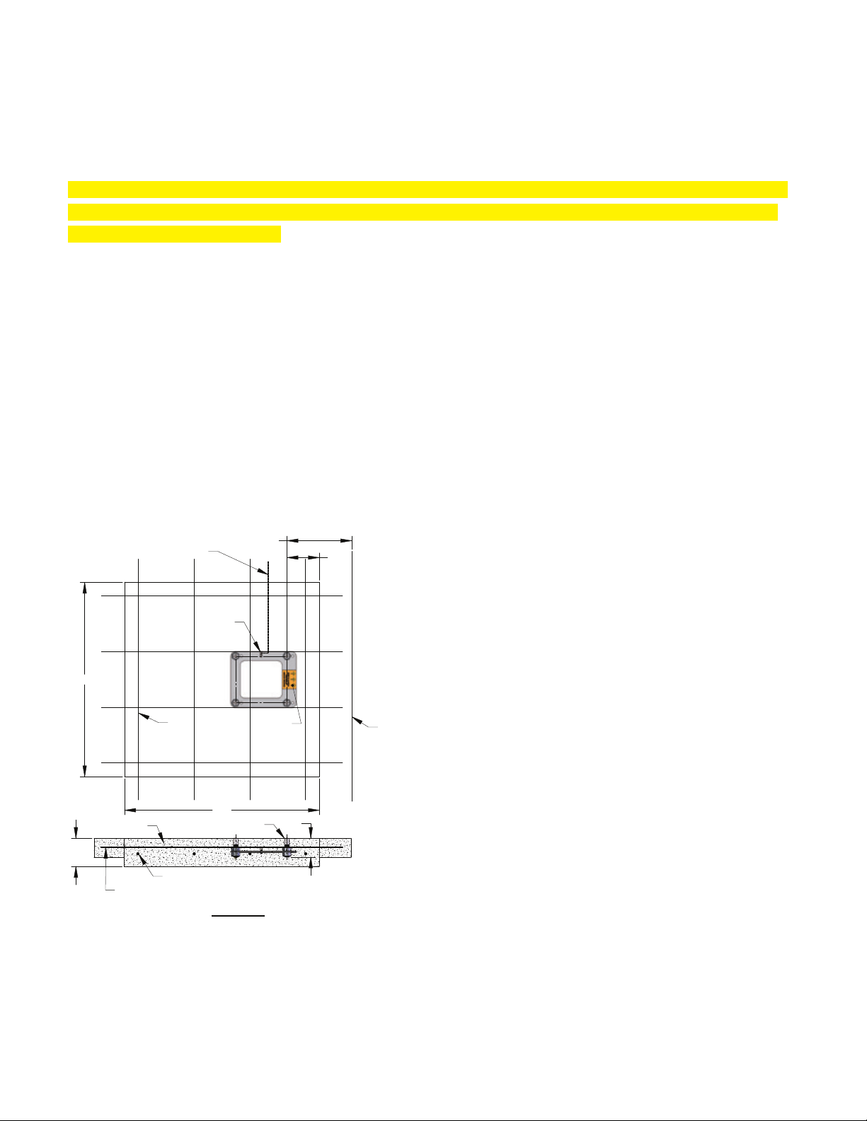
3. Set the anchor system in place. For ADA compliance and clearance, make sure the
center of the large anchor jig plate holes are between 14.5 and 19 inches from the pool’s
edge. SEE FIGURE C
4. Make sure the top of each anchor body is
ush with the FINISHED deck surface. Each
anchor body can be adjusted individually by
turning the nuts with a large wrench.
5. Bond the anchoring system by using the
bonding lug on the anchor jig plate. Bond
the system according to your local code
requirements. (See NEC Article 680.26)
SEE FIGURE C
6. Pour your concrete and nish the pool deck
surface.
SEE FIGURE A, PAGE 7
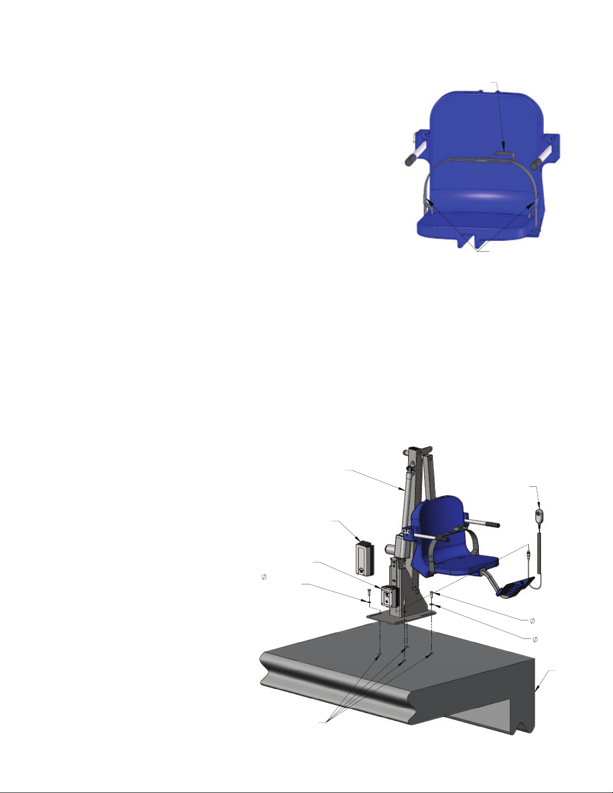
7. Once the concrete has cured the lift is ready
to be mounted to the anchoring system.
NOTE: For installations where a new deck is being poured, or where a dedicated pad is being poured
just for the pool lift, the concrete must satisfy the ADA requirements outlined on page 3 of this manual.
Your pool deck must be at least 3 feet - 6 inches long by 3 feet - 6 inches wide by 6 inches
thick. It must be reinforced with 4 sticks of #5 rebar each way, 3 inches clear (min) from
the bottom of the footing.
Anchor Installation: New Construction
4"
6"
FLUSH W-DECK
#5 REBAR E-W (4 PCS)
DRILL & EPOXY INTO EXISTING
SLAB (5" MIN EMBED)
2500PSI MIN
42"
2.5"
MIN
14.5" TO 19"
SETBACK
42"
LABEL
BONDING
-LUG
POOL
WALL
8-AWG SOLID-COPPER WIRE
(ATTACH TO BONDING-GRID)
#5
REBAR
*[37 TO 48cm]
*SETBACK DIMENSIONS ARE FOR
FLAT DECK
APPLICATIONS.
FOR SLOPED DECKS OR OTHER FEATURES, CONTACT AQUA
CREEK BEFORE INSTALLATION.
FIGURE C
8