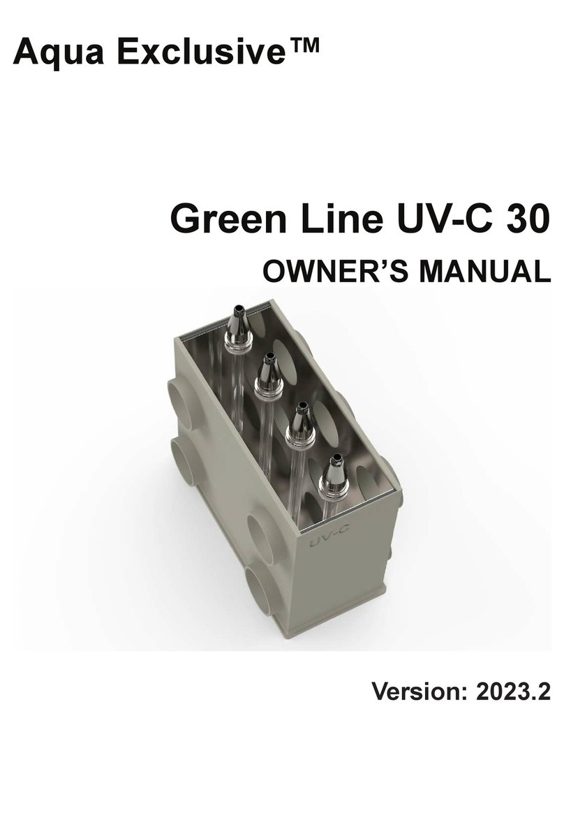
Aqua Exclusive DRUM FILTER C-25 EVO User manual

Aqua Exclusive™
DRUM FILTER C-25 EVO
OWNER’S MANUAL
www.aqua-exclusive.com - www.aqua-exclusive.com - www.aqua-exclusive.com - www.aqua-exclu

SAFETY INFORMATION
PRODUCT SPECIFICATIONS
©2019-2021 AQUA EXCLUSIVE
The Drum Filter C-25 EVO Manual is also available online. To download or view the manual,
you can also go to www.aqua-exclusive.com/drum-lter-c-25-evo.
For more information about our company, you can go to www.aqua-exclusive.com/about-us.
If you have any questions or concerns about your lter, you can call to +316-2515-7626, email
All specications and descriptions contained in this document are veried to be accurate at
the time of printing. However, because continuous improvement is a goal at Aqua Exclusive,
we reserve the right to make product modications at any time. To communicate any inac-
curacies or omissions in this document, please send an email to: ownersmanualfeedback@
aqua-exclusive.com.
All information in this document and all product software is subject to copyright and other in-
tellectual property rights of Aqua Exclusive™ and its licensors. This material may not be mod-
ied, reproduced or copied, in whole or in part, without the prior written permission of Aqua
Exclusive™ and its licensors. Additional information is available upon request. The following
are trademarks or registered trademarks of Aqua Exclusive™ in the Netherlands and other
countries: C-30 PRO, C-25 EVO.

Aqua ExclusiveContents
Safety & Requirements...................................................................................................2
Overview...........................................................................................................................3
Filter Overview........................................................................................................................................3
Setup.................................................................................................................................8
Gravity.....................................................................................................................................................8
Pump Fed................................................................................................................................................8
Installation......................................................................................................................10
Water Level Sensor..............................................................................................................................10
UV-C System.........................................................................................................................................11
Connect Filter........................................................................................................................................12
Flexible Coupling...................................................................................................................................12
Rinse Pump..........................................................................................................................................13
Water Level...........................................................................................................................................14
Controlbox............................................................................................................................................15
Maintenance..................................................................................................................16
Disassembly.........................................................................................................................................16
Bypass...................................................................................................................................................16
Slip Clutch.............................................................................................................................................16
Torque...................................................................................................................................................16
Replacing Filter Panel...........................................................................................................................17

Aqua Exclusive
FUNCTION
The Aqua Exclusive Drum Filter C-25 EVO is an modern and very eective all in one lter
system. Connecting separate lter equipment is a thing of the past. The C-25 EVO is made for
(koi) ponds, (large) aquariums and sh farms.
The lter consists of 3 main elements:
1. Rotary Drum Filter - RDF (Mechanical lter )
2. Moving Bed Bio Chamber (Bio Filter)
3. High Output UV-C system (Disinfection).
This lter cleans itself when necessary, everything works fully automatic.
The system is equipped with a 70 micron lter panel and has two 4”/110mm inlets and one
4”/110mm outlet. This ensures a water ow of 5.250 Gallons (20.000 Liter) per hour. For opti-
mal functioning of your bio lter, we recommended 2.650 Gallons (10.000 Liters) per hour.
SAFETY WARNINGS
• The device may only be connected to an electrical installation that meets the legal stan-
dards. A residual-current device (30 mA) and earthed wall socket are required. If in doubt,
consult a qualied installer.
• Both the Drum Filter and the control box must be installed in a dry, sheltered place. Not in
direct sunlight.
• Keep the power plug free from moisture. Prevent water from running along the power
lead into the socket.
• The device is suitable for fresh water.
• The device is suitable for water temperatures of 4 to 40 °C. If exposed to temperatures
outside these limits, the device must be fully isolated from the water circuit.
• Before commissioning, check the entire device, mains lead and plug for damage. If dam-
age is found, the device may not be used. Have the damage assessed by the dealer.
• The device may only be switched on when there is sucient water ow.
• When opening the lid/maintenance cover the power to the device/control box must al-
ways be switched o.
• The UV-C lamp may still be hot up to ten minutes after it is switched o.
C-25 EVO OWNER’S MANUAL
Safety & Requirements
2
Read the entire manual before use/installation of the system!

Overview 3
Aqua ExclusiveFilter Overview
Figure 1: Front and side view of the Drum Filter C25 EVO.
1. Drum lter by-pass caps
2. Air hose tank transit
3. Drum lter controlbox
4. Build-In UV-C system
5. Drum frame
6. Spray bar connector
7. Drum motor
8. Water level sensor DMX cable
9. Water level sensor
10. Spray bar
11. Filter panel
12. Filter panel clambs
13. Filter inlets 2x (4”/110mm)
14. Drain gutter
15. Air hose tank transit
16. Air hose for moving bed
17. Moving bed lter media
18. Filter outlet 1x (4”/110mm)

Aqua Exclusive Filter Overview
Figure 2: UV-C System overview
1. Power Plug USA
2. Ballast 40W
3. Tank transit connector
4. Rubber O-Ring A
5. Quarts sleeve
6. Rubber O-Ring B
7. High Output Bulb
8. Bulb Connector
9. Threaded Connector Ring
C-25 EVO OWNER’S MANUAL4

Aqua ExclusiveFilter Overview
Overview 5
1. Manually Rinsing Button
2. UV-C Power Socket
3. Rinse Pump Power Socket
4. Fuse 1
5. Controlbox Power Plug
6. Water Pump Power Socket
7. Drum Motor Power Socket
8. Fuse 2
9. Controlbox ON/OFF Switch
10. DMX connector water level sensor\
Figure 3: Controlbox overview

Aqua Exclusive
C-25 EVO OWNER’S MANUAL
C-25 EVO
Connecting separate lter equipment is a thing of the past with the C-25 EVO. A modern and
very eective RDF lter with little to no maintenance! This is a 3-in-1 lter that anyone can
install; mechanical lter (Drum Filter, RDF), bio lter (Moving bed) and disinfection (UV-C sys-
tem). This lter cleans itself when necessary, everything is fully automatic! It is not just a lter,
but years of experience combined with high quality materials!
This lter system removes dirt particles up to 70 microns in a quick mechanical way, removes
ammonia, nitrite and nitrate with a bio lter and kills bacteria, viruses and even fungi with
UV! The C-25 EVO is compact and reliable. It is a simple but very ecient lter system for (koi)
ponds, (large) aquariums and sh farms (aquaculture).
The housing of the C-25 EVO lter consists of a polypropylene (PP) container with an interme-
diate bulkhead. The partition is provided with a silicone sealing strip mounted on the ange,
separating the dirty water from the clean water. In the partition wall, there are 2 holes, which
are covered with a lid. In case of failure of the drum control, this lid may be removed so that
the water can ow past the drum, but without any lter function. Through this, the biological
ltration can still be operated until the error rectication of the drum.
6
Filter Overview
Drum Filter
The drum lter consists of a polypropylene (PP) box with two chambers. In the rst chamber
there is a drum with a lter panel. Water ows through the lter and the dirt sticks on the
inside of the drum. The special at nozzles spray the drum clean with water from the system.
The water with dirt is removed through the drain gutter into the sewer. The water level sen-
sor detects when the cleaning process should be activated. Due to this sensor, the lter only
rinses when necessary!
Bio Chamber
Once the grime and dirt particles have been removed from the pond water, the water then
enters the moving bed bio chamber where healthy bacteria is created with the help of the
white bio media. Harmful degradation is transformed into a healthy bacteria environment
that is then returned to the pond keeping the water clean, clear and stable.
Water Level Sensor
The water level sensor detects when the cleaning process should be activated. Due to this
sensor, the lter only rinses when necessary! At the beginning the lter will run a little more
often, but as the water gets cleaner you will notice that it will take longer. This also depends
on your ow and how many microns your lter panel is. We supply the drum lter C-25 EVO
with a 70 micron lter panel as standard, which we also recommend this for koi ponds.

Overview 7
Aqua ExclusiveFilter Overview
UV-C SYSTEM
The C-25 EVO is equipped with our newest UV-C technology. A 40watt UV-C system with high
output uv lamp is build inside the lter underneed the drum.This means that UV equipment
in your pipe system can be dispensed with, which promotes optimal ow. The sophisticated
design and high quality materials produce a high UV-C radiation. The wavelength of the UV-C
system is exactly 253.7nm, and this high level of radiation kills almost all bacteria, viruses and
even fungi. This system produces 60% more light than normal UV-C lamps and ensures clean
and clear water!

C-25 EVO OWNER’S MANUAL
Aqua Exclusive
8
Setup
Installation
Before starting the installation of the C-25 EVO you need to know which setup you are go-
ing to use. The C-25 EVO can be used for both a gravity and pump fed setup. We will explain
the two main systems below. Do not hesitate to reach out if you have any questions about
the dierent setups. Please contact us at [email protected] or start a live chat at
www.aqua-exclusive.com.
Pump Fed setup
Besides the gravity setup, you can also go for the pump fed setup. It’s called a pump fed
setup because the water ows into the lter through a circulation pump. The advantage of
the pump fed setup is that the water level of the pond does not have to be the same as that
of the lter. For example, this means you do not have to place the lter in the ground, even
though your pond is completely in the ground. The big dierence with the gravity setup is
that the water ows from the pond to the lter by a pump.
Figure 5 shows an example of a pump fed setup where the lter is placed on the oor next to
the lter. You can see how the water ows by the arrows. The circulation pump in the pond
ensures that the dirty water ows from the pond to the lter. Due to gravity the clean water
will ow from the lter back to the pond.
As the name suggests, the gravity setup is based on gravity. Due to gravity, the water ows
to the place where the water level is lower. It’s called a gravity setup because the water ows
into the lter due to gravity. The main characteristic of the gravity setup is that the water in
the pond is equal to the water level in the lter. For optimal use of the volume of the lter,
the pond should be close to the maximum water level in the lter. This ensures that the lter
will be used optimally. To keep the water circulating, a circulation pump must be placed at the
outlet of the lter.
Figure 4 shows an example of a gravity setup where the pond is build a little above the
ground so the water level in the pond is close to the maximum water level in the lter. You
can see how the water ows by the arrows. The clean water ows through a circulation pump
to the pond. This causes the water level in the lter to drop and the water level in the pond
to increase. Subsequently, the dirty water will ow back to the lter by gravity via the pond
skimmer and the bottom drain.
Gravity setup

Setup 9
Aqua ExclusivePump Fed
Figure 4: Overview of gravity setup.
Figure 5: Overview of pump fed setup.

C-25 EVO OWNER’S MANUAL
Aqua Exclusive
Location of the Water Level Sensor
Gravity Setup: the water level sensor should be placed downwards in the chamber of the
drum, and both oats must be under water. Explanation: when the lter panel is full of dirt,
the water can no longer pass through the panel. This will cause the water level in the cham-
ber of the drum to drop, and the top oat will move downwards. The water level sensor de-
tects that the position of this oat has changed and the cleaning process will get activated.
Pump Fed Setup: the water level sensor should be placed upwards in the front chamber of
the lter, and both oats must be above the water. Explanation: when the lter panel is full
of dirt, the water can no longer pass through the panel. This will cause the water level in the
front chamber to rise, and the bottom oat will move upwards. The water level sensor de-
tects that the position of this oat has changed and the cleaning process will get activated.
10
Water Level Sensor
Figure 6: Placement of the water level sensor for the gravity and pump fed setup.
You might have to reposition the water level sensor based on which setup you will be using.
The lter comes standard with the water level sensor next to the drum, this is for the gravity
setup. If you want to use a pump fed setup, you need to move the water level sensor to the
front chamber of the lter and turn it upwards, see gure 6.

Installation 11
Aqua ExclusiveUV-C System
Step 1: Insert the rubber O-Ring A into the transit connector.
Step 2: Gently slide the quartz sleeve into the transit connector.
Step 3: Insert the rubber O-Ring B into the quarts sleeve.
Step 4: Gently slide the UV Bulb into the quarts sleeve.
Step 5: Put the UV bulb in the UV connector and put the UV connector in the transit
connector.
Step 6: Tighten the threaded connector ring properly. Fixed is xed, do not turn the ring
too far!
Figure 7: Steps to connect the UV-system to the Drum Filter C-25 EVO.
Connecting the UV-System

Aqua Exclusive Connect lter
Figure 8: Flexible coupling
1. Filter outlet 4” (110mm)
2. Flexible Coupling 4” (110mm)
3. PVC Pipe
We recommend to use exible couplings between the lter and the pvc pipes, see gure 8.
Connect lter
C-25 EVO OWNER’S MANUAL12

Aqua ExclusiveRinse Pump
1. Filter outlet 4” (110mm)
2. Flexible Rubber Tee Coupling 4” (110mm)
3. PVC Reducer ring
4. Hose/PVC pipe to Rinse Pump Inlet
5. Spray Bar
6. Hose/PVC pipe from Rinse Pump Outlet to Spray Bar
7. Rinse Pump
Figure 9: Overview of the C-25 EVO with a rinse pump.
Installing the Rinse Pump
• It is important, however, that high-pressure hose/PVC pipe is used for this purpose.
• The pump generates a pressure of 3 bar. Pressure peaks of 4 bar may occur during start-
up. Therefore do not use sewer & drain PVC.
• The high-pressure pump itself must be placed in a moisture-free location below the water
level.
1. Place a exible tee coupling (2) at the output (1) of the lter. One output of the tee cou-
pling is for the rinse pump (7) and the other serves as a passage to the pond pump.
2. Connect the output of the tee coupling to the rinse pump (7) and the rinse pump to the
spray tube (5).
Installation 13

C-25 EVO OWNER’S MANUAL
Aqua Exclusive
14
Water Level
WATER LEVEL
Figure 9: Water level C-25 EVO
1. Remove the cover of the housing and check that the oat (gure 6) is in the lower position.
(If you are using a pump fed setup you have to reposition the water level sensor, see page
8 and 10 for more information)
2. Open the gate valve on the inlet, and the outlet if present, in order to ll the lter system
with water.
3. Let the lter ll until the correct water level has been reached.
4. Check the water level in the housing.
5. Check all pipes, hoses and connections for leaks.
6. Place the lid back on the housing.
It is important to maintain the correct water level. A lower water level will not make the sys-
tem work properly and higher water levels can cause leaks.
Water level
- Gravity setup: 34,5 cm (13.5”)
- Pump fed setup: 32,5 cm (12.8”)

Installation 15
Aqua ExclusiveControlbox
Controlbox
1. Connect the plugs of the devices to the appropriate sockets on the control box, see gure
12.
2. Insert the power plug of the control box (5) in the appropriate socket and switch on the
system by toggling the switch (9).
3. Hold the button (1) for ten seconds to activate the motor and high pressure pump.
4. After about 20 to 30 minutes the rinse cycle should be repeated automatically.
5. For longer delays, you can adjust the height of the oat, see gure 6.
Please note: Immediately after the lter is installed/used, the rinse cycle may be very short
and will increase in length as the contamination/oating debris decreases, up to a cycle of 20
to 30 min.
Warning: when adjusting the oat the power supply must always be switched o.
1. Manually Rinsing Button
2. UV-C Power Socket
3. Rinse Pump Power Socket
4. Fuse 1
5. Controlbox Power Plug
6. Water Pump Power Socket
7. Drum Motor Power Socket
8. Fuse 2
9. Controlbox ON/OFF Switch
10. DMX connector water level sensor
Figure 10: Controlbox

C-25 EVO OWNER’S MANUAL
Aqua Exclusive
16
Maintenance
Maintenance & Disassembly
The device requires maintenance at least once a month. During maintenance the power sup-
ply must be disconnected. The screen panel should be checked for wear and tear.
1. Disconnect the power supply and close the piping.
2. Ensure that the water can drain out of the housing.
3. Turn the entire drum one revolution by hand and check the assembly for wear. If neces-
sary, you can replace the screen panel (see the next page).
4. Also check the drain for any lamentous algae/dirt that may have collected.
5. Place the lid back on the housing and put the plug back in the socket.
Activation Of ‘Drum Filter’ Bypass:
During a treatment or in the event of a problem the drum can be short-circuited by means of
the bypass.
Setting Slip Clutch Torque 65nm
The drive shaft is tted with a slip clutch that allows the shaft to turn freely if something pre-
vents the drum from turning.
Setting Torque:
1. Remove motor cover.
2. Place torque spanner on M10 nut on the shaft.
3. Prevent drum from turning and torque to 65nm.
Activation Of Bypass:
1. Switch o control box.
2. Remove two red caps from the partition wall.
3. Connect circulation pump to 110V mains outlet

Maintenance
Aqua ExclusiveReplacing Filter Panel
17
Replacing Filter Panel
Once you have established that the screen panel is showing wear, it is important that you
replace it with a new screen panel as soon as possible. This will ensure the continued optimal
performance of the lter. Follow the steps below to replace the lter panel.
1. Disconnect the power supply.
2. Ensure that the water can drain out of the lter.
3. Turn the drum by hand until the fastening strip and lter panel clamps are pointing up-
wards.
4. Remove the screws from the fastening strip.
5. Loosen the lter panel clamps.
6. Remove the drain sewer, by unscrewing the two mounting screws at the front.
7. Remove the screen panel and replace it with a new one slowly.
8. Tighten the hose clamps and fastening the strip again. Check if the assembly is attached
correctly.
9. Put the lid back on the housing.
10. Finally insert the plug in the socket and hold the button for 10 seconds. The motor and
high pressure pump are activated again.

Aqua Exclusive™
Publication date: March 21, 2021
This manual suits for next models
2
Table of contents
Other Aqua Exclusive Water Filtration System manuals
Popular Water Filtration System manuals by other brands

Pentair
Pentair FLECK 5600 Service manual

Doheny's
Doheny's 5166 Installation, operation & parts

Gemlogis
Gemlogis VISTA Pro quick start guide

Drinkpod
Drinkpod DP-RO-PRO user manual

Luminor
Luminor Glacier UV LED GUV-4S Operation & installation instructions

Evolution Aqua
Evolution Aqua EAZYPOD AUTOMATIC Installation and instruction manual

Ecoplus
Ecoplus EP-600-TAC Installation & owners guide

AQUA FORTE
AQUA FORTE DRUMFILTER XL instruction manual

Waterco
Waterco MultiCyclone Installation and operation manual

Bluewater
Bluewater Pro Series quick guide

Bluewater
Bluewater Pro Series Complete user's manual

Aqua Medic
Aqua Medic Premium 90/150 Operation manual