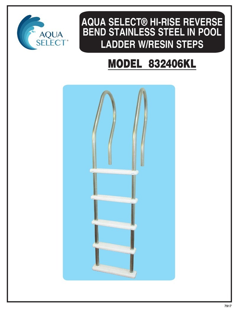
Aqua Select 832402B User manual

8256
Below are the options available with use of the Aqua
Select® Everest Step. The cartons and instructions
necessary will vary depending on which set-up you
have purchased. Please find the model you purchased
on the next page and note the information regarding
location of the instructions and assembly.
MODEL 832402B
(1 CARTON)
(1) 832402B — Aqua Select® Everest Step
(1) 832405B — Aqua Select® Crossover and Enclosure
(1) 832406 — Aqua Select® Gate
(1) 832402B — Aqua Select® Everest Step
(1) 832420 — Aqua Select® Outside Ladder
CARTONS REQUIRED CARTONS REQUIRED
FOR USE WITH:
Aqua Select® Everest
STEP W/FLIP UP OUTSIDE
LADDER
(832401BK)
FOR USE WITH:
Aqua Select® Everest
BRIDGE SYSTEM
(832421B)
AQUA SELECT® EVEREST
ABOVE-GROUND POOL STEP
(1) 832402B — Aqua Select® Everest Step
(1) 832405P — Aqua Select® Pickets
(1) 832406 — Aqua Select® Gate
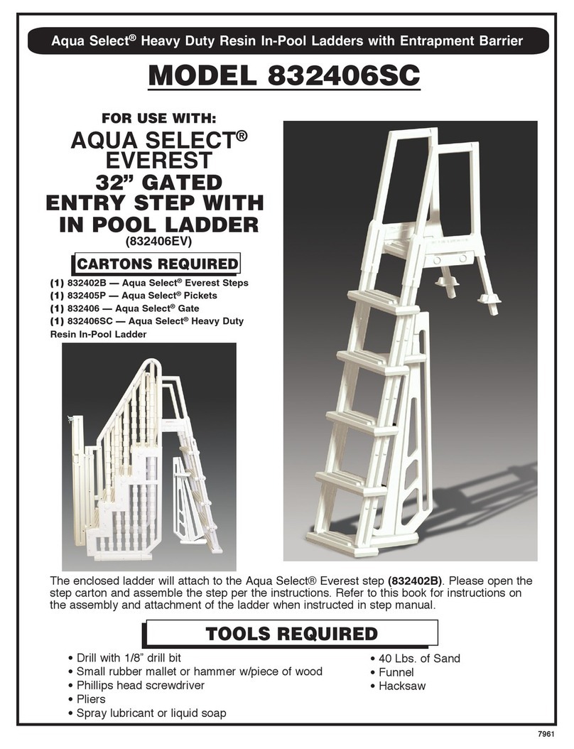
(1) 832406SC — Aqua Select® Heavy Duty In-Pool
Ladders
FOR USE WITH:
Aqua Select® Everest
GATED ENTRY WITH
IN POOL LADDER
(832406EV)
CARTONS REQUIRED

2
•Small rubber mallet or hammer w/piece of wood
•Phillips head screwdriver
•Pliers
•Liquid soap or lubricant
•40 lbs. of sand (sold separately)
•Funnel
TOOLS REQUIRED
AQUA SELECT® EVEREST STEP
(832402B)
This carton (832402B)contains ALL the necessary pieces and instructions for installation of your new
step. Please follow all instructions for proper installation of this step.
AQUA SELECT® BRIDGE SYSTEM
(832421B)
There are four cartons necessary to install your new bridge. You should have 2 step cartons
(832402B)which include the instructions necessary to install the steps only. The third carton is marked
(832405B)and this contains the crossover necessary to connect the two steps. The instructions for the
assembly and installation of the crossover are located in the crossover box. Carton 4 is the gate carton
(832406)which includes the necessary components for the gate and instructions for gate installation.
NOTE
The sequence of the instructions may vary at points depending on the type
of step system that you have purchased. If there are different instructions for
your system, it WILL BE indicated within the step.
Please follow these notes to avoid additional steps and wasted time.
The Ladder must be installed based on Manufacturer’s Instructions
•One person on the Ladder/Stair at a time
•This Ladder is designed and manufactured for a specific Pool Wall Height
and/or Deck of the Pool
•For Entry/Exit of pool, face the ladder at all times
•Remove and secure Ladder when pool is not occupied
•The Ladder will be suitable up to 54” Maximum Pool Height
IMPORTANT SAFETY INSTRUCTIONS
PLEASE READ PRIOR TO ASSEMBLY/USE
AQUA SELECT® EVEREST STEP WITH FLIP UP OUTSIDE LADDER
(832401BK)
AQUA SELECT® EVEREST STEP WITH IN POOL LADDER
(832406EV)
This is carton 1 of 2. The step and the necessary instructions for installation are included within this
carton. You should have a second carton labeled (832420) which contains the outside ladder for
this system. All the necessary instructions for installation of the ladder are located inside the second
carton.
There are four cartons necessary to install your entry system. You should have 1 step carton
(832402B) which includes the instructions necessary to install the step only. The second carton is
marked (832406SC) and this contains the In Pool Ladder as well as assembly and attachment
instructions to the step. Cartons three and four are (832406) Gate and (832405P) Pickets each box
contains assembly and attachment instructions to enclose your entry system.

PARTS & HARDWARE FOR STEP
A. LONG HANDRAIL POST (2)
(AC LONGPOS)
B. SHORT HANDRAIL POST (2)
(AC SHORTPOS)
C. STEPS (4)
(832402BS)
D. RISERS (4)
(AC RISERS)
E. BASES (2)
(AC BASE)
F. MOUNTING BRACKETS (2)
(832402MB)
3
G. HANDRAILS (2)
(832402SR)
H. SIDE PANELS (2)
(AC PANELS)
I. LOCK
CAPS (16)
(832402LC)
J. HARDWARE
(AC HDW30163)
•14 - 1-1/4” screws
K. DANGER STICKERS
(AC DNGRSTIK)
M. STEP BRIGHT LIGHT
(AC 08478)

PART # MODEL # DESCRIPTION QTY
1 832402SR Steprail 2
2 AC LONGPOS Long Post 2
3 832402BS Steps 4
4 832402MB Mounting Bracket 2
5 AC RISER Step Raisers 4
6 AC SHORTPOS Short Post 2
7 832402LC Lock Caps 16
8 AC PANELS Side Panels 2
9 AC BASE Step Base 2
4
ANTIGUA STEP PARTS
1
2
3
4
5
6
7
8
9

STEP 1
•Lay one of the side panels (H) down on a flat surface.
•Each step (C) has a groove where the riser will slide in
which is located on the bottom of each step.
•Line up a step (C) by positioning the connected
dowels on the step with two of the round holes on the
side panel (H). NOTE: Make sure that the treads on the
step are facing towards the TOP of the side panel (the
skinnier part of panel) and that the riser groove on the
step is towards the back of the step.
•Push the step until it clicks in place. Repeat for each of
the three remaining steps (C). If necessary, you may
use the rubber mallet or hammer with wood on top to
tap into place.
STEP 2
•Insert a riser (D) between each
of the steps. Locate the hole
in the center of the riser. This
hole should face towards the
back of the side panel.
•The riser should slide right into
the grooves on the steps and
the square notches should fit
right into the recessed
openings on the panel.
•Elect the riser position you
want the light to be installed
and slide the step bright riser
into that position. (Note: you
will have an extra riser when
assembly is complete)
•Repeat for each of the three
remaining risers.
STEP 3
•Once all risers are in place, line up second
side panel with the connected dowels on
installed steps.
•Push down on side panel to lock in place,
if necessary use rubber mallet or
(hammer with piece of wood) to fully seat
side panel.
TOP OF PANEL
5

STEP 4
•Leave the side panel facing upward and position one
of the lock caps (I) centered over any hole on the
side panel.
•Using a small rubber mallet or a (block of wood and
a small hammer), tap on the locking cap until it is
secured over the pin sticking through the side of the
step and is flush with the side panel.
•Repeat this procedure for each of the additional
seven openings on this side of the step.
•Flip step so that other side panel is facing upwards
and repeat above for the eight holes on this side.
6
STEP 5
•Leave the side panel facing upward and
position one of the bases (E) under the side
panel with the channel against the step.
•Secure the base to the side panel with
two zip ties. There is a molded groove
in the base for placement of the zip tie.
Tighten zip tie securely.
•Repeat for opposite side.
NOTE
To prevent damage to liner, make sure that the locking tab on zip
tie is positioned so that it will NOT come in contact with liner.
NOTE
Zip tie should catch and lock when pulled tight, if it does not then
turn the zip tie over and reattach.

7
STEP 6
•In order for step to sit properly,
it must be weighted in place
using approximately 50 lbs of
sand. To weight step, place
funnel in opening of side panel
on top step. Pour 25 Lbs. of
sand into each side of the step.
•Once step is placed in the pool, tip the
step forward and move it left and right to
ensure that air escapes and water enters
the steps and risers. This will help keep
the step stationary in the pool.
Place funnel up
here and pour
sand through
these posts
NOTE
You may need to rock the step back and forth to distribute
the sand so the 25 Lbs. will fit in each side of the step.
STEP 7
•Place the assembled step INSIDE the pool where you would like to enter the pool.
**When lifting the step into the pool it is recommended that two people lift to avoid
injury. Filter should be turned off to stop water circulation.
NOTE
When installing a step inside of your pool it is recommended to
install a step mat underneath to protect your liner.
This item is sold separately.

8
STEP 8
•The two long handrail posts (A) should be installed into the holes located at the
back of the step.
•When installing these posts, make sure that the closed end goes into the opening
and that the open end is facing up.
•Once in place, secure using (2) screws from hardware bag (J).
STEP 9
•If you are reading this step, then you will be attaching
this staircase to an existing deck at the pool site. If you
are NOT installing this step to a deck, please refer to
the above notes for your next step.
•Locate mounting brackets (F) and slide one over each
of the long handrail posts. These will be used to secure
your step to your decking.
•Adjust mounting brackets height-wise so that they are
even with your deck. Once these are even, make sure
step is where you would like it in pool. Make sure the
upright posts are as close as possible to pool top rails.
NOTE
If you are having a problem getting the handrail posts in due to the
sand, rock the step left and right to distribute sand.
NOTE
Step MUST be secured to deck to prevent rocking or tipping. If the mounting
brackets do not reach the deck, you will need to extend that part of the deck
surface so that the brackets can be screwed in place.
•Attach mounting brackets by screwing into deck through two of the three holes on each mounting
bracket (choose the openings that best fits your deck). The screws necessary for attachment are
NOT included as there are several types of deck materials and the necessary screws will vary.
**IF YOU ARE INSTALLING THE AQUA SELECT® EVEREST STEP with FLIP UP
OUTSIDE LADDER PLEASE REFER TO 832420 INSTRUCTIONS AT THIS TIME.
**IF YOU ARE INSTALLING THE AQUA SELECT® EVEREST BRIDGE SYSTEM, PLEASE
REFER TO 832405B INSTRUCTIONS AT THIS TIME.

9
STEP 10
SAFETY INFORMATION
•Lubricate inside of long and short handrail posts with
liquid soap or lubricant.
•Attach handrails (D) to handrail posts by pushing into
posts. The more curved part of the handrail is meant to
be installed in the long handrail post.
•Using (4) screws from hardware bag (J), secure
handrails in place.
•Stick one danger sticker (K) on each handrail so that
one faces inside the pool and the other faces the
outside.
•When lifting heavy or awkward loads, it is suggested that two people lift
to avoid injury.
•DO NOT use the pool steps for any purpose other than that for which it
is intended.
•Maximum weight on steps should NOT exceed 350 lbs.
WARNING
Exceeding the recommended weight limit may cause the step
to fail and may result in injury.
MAINTENANCE
•Step/ladder/bridges must be removed for winter, failure to do so can
cause the step to crack.
•When removing step/ladder/bridges for winter, it is recommended that you
spray down step with hose water to rinse off any chemical residual prior to
storing.
•When storing step/ladder/bridges for winter, it should be protected from
the elements and stored either in a shed or garage, or covered with a tarp.

10
STEP 11
•The low voltage wire running from the light to the controller can be run under the step
and under the mounting bracket if using with an existing deck.
•The low voltage wire can then be run down under the deck to the control pad and
transformer.
•The control pad can be mounted on the side of an existing deck or post outside the pool.
For outside of Pool Bridge installation only.
For Bridge Entry Systems the control can be installed on the outside step.

11
•The Step Bright controller allows you to either
manually or automatically control the light.
•The low voltage connects to the power cord
attached to the controller. Simply plug the
cords together and tighten the locking ring
connector.
•To power on you light press the on/off button
on the control pad (transformer needs to be
connected to power source)
•Once light is powered on select either manual
operation or automatic operation by pressing
the “manual/ auto” button.
•For manual operation — the Light OK indicator will illuminate.
•For automatic operation — light will turn on at sunset and off at dusk – the photo
sensor indicator will illuminate.
•The other cord coming from the controller
(left side/ bottom) connects to the
transformer cable the same way.
•The plug ends are different so you cannot
connect the cables incorrectly.

12
PLEASE
READ
BEFORE
USING
THIS
LADDER
SAFETY
NOTICE
IMPORTANT
To prevent
Entrapment or
Drowning,
DO NOT SWIM
through, behind
or around the
ladder
DANGER
DANGER
WARNING
Entry/Exit of
Pool,
Face the
Ladder at
all times
DANGER
DANGER
WARNING
WARNING
is ladder is
designed and
manufactured for
Aboveground,
Semi-Inground
Flat Bottom
Pools
48”, 52” and 54”
in wall height
and pool decks
48”, 52” and 54”
in height
Table of contents
Other Aqua Select Ladder manuals
Popular Ladder manuals by other brands

TUBESCA-COMABI
TUBESCA-COMABI PROFORT X'TEND operating instructions

HSS Hire
HSS Hire Conservatory Roof Access System Operating & safety guide

Easylife
Easylife Genius EL4672 instruction manual

Confer Plastics
Confer Plastics 7100X ASSEMBLY, INSTALLATION AND USE MANUAL

ST Quadrat
ST Quadrat LUX-top LS Product information

Vestil
Vestil LAD Series instruction manual

Instant Upright
Instant Upright Span 300 Series instruction manual

CSH
CSH QG.830 Series Instruction manual for installation

Westfalia
Westfalia 87 93 46 instruction manual

IRUDEK
IRUDEK IruLadder instruction manual

Branach
Branach All Terrain FED-AT 4.0 User instructions

Rainbow Attic Stair
Rainbow Attic Stair ProTech-12 Series installation guide