Page - 3
1 - Installation
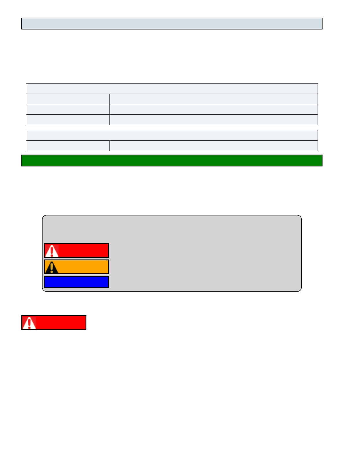
WARNING Failure to heed the following may result in injury or death.
lInstallation of this equipment by anyone other than a qualified installer can result in a safety hazard.
lThe information contained throughout the "Installation" section is intended for use by qualified installation
technicians familiar with the swimming Pool / Spa safety standards.
NOTICE
Failure to heed the following may result in damage to equipment.
lFailure to protect equipment against corrosive conditions will adversely affect the life of the equipment and will
void equipment warranty.
1.1 Positioning Equipment
NOTICE
Failure to heed the following may result in damage to equipment.
lDo not install equipment inside of a building.
Outdoor Use Only
Do not install equipment inside of a room or building.
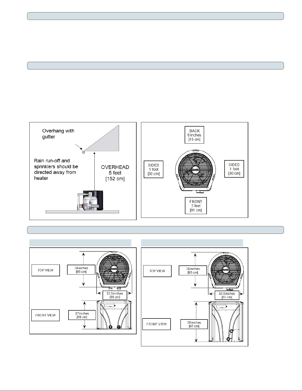
lChillers require unobstructed air flow for proper operation. Chillers should never be installed indoors or in a
location where air flow is restricted. See "Clearances" on page 4.
Controlling Irrigation and Rainwater Runoff
lIrrigation water may damage chiller components. Direct irrigation water away from the chiller.
lThe chiller will withstand normal rainfall. Do not allow a roof slope to direct rainwater onto the chiller. Have a
gutter installed on the roof edge to direct this water away from the chiller. Or install the chiller in another
location.
Planning for Condensation
The chiller can produce a large amount of condensation. The amount of water depends on air temperature and
humidity.
lInstall the chiller with enough height to allow for water drainage.
lPlan for water drainage as needed.
nSee "Condensation Drain Kit (# STK0202)" on page 26.
Mounting Pad Requirements
lThe chiller's base must be installed on a flat and level surface that completely supports the entire base.
lBuild the chiller pad out of concrete or other code-approved material.
lConfirm the pad can support the weight of the chiller. See "Weights" on page 26.
lElevate the pad enough to allow for drainage.
lMake sure the pad is flat and level.
lHave the pad extend at least 6 inches from the chiller base in all directions.
lDo not install the chiller on soil or grass.
lDo not allow the chiller base to touch the building's foundation.
lDo not place the chiller directly on a concrete floor. This can case noise to be transmitted to an occupied space. If
necessary install vibration dampers between the chiller base and floor.
lEquipment pad must meet all requirements of authorities having code-related jurisdiction.