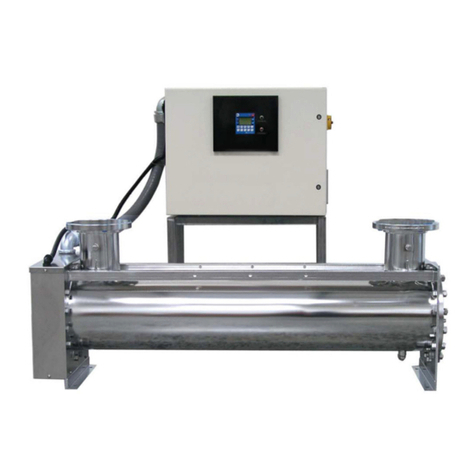
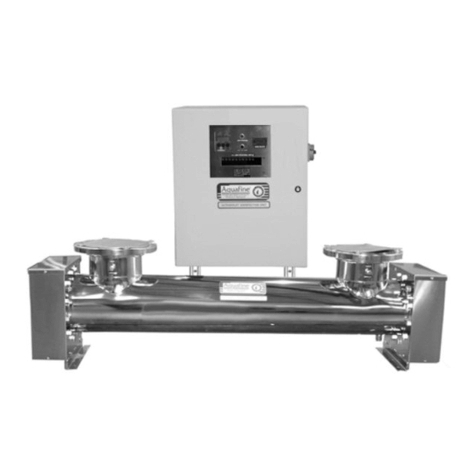
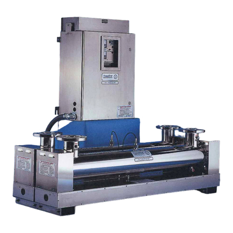
Aquafine Avant Series Owner's manual

Avant™ Series
Operation and Maintenance
User Manual
Original Instructions
Edition 5
Aquafine Corporation®2023 All rights reserved. Printed in Canada. DC650101-05-02

2Original Instructions
If you require technical assistance, please contact Aquafine Corporation Technical Support using the
contact information below:
At the time of publishing, the information within this document is current. Due to continuous improvements,
we may have future changes and recommendations which will be sent via product bulletins.
Place system label here
(Do not translate this tex t. )
Telephone: 1-661-257-4770
E-mail: techservice@trojantechnologies.com

Original Instructions 3
Table of Contents
Section 1 Specifications........................................................................................................................ 7
Section 2 Safety Information ................................................................................................................ 9
2.1 Use of Hazard Information ........................................................................................................... 9
2.2 Precautionary Labels ................................................................................................................... 9
2.3 Safety Precautions ..................................................................................................................... 11
2.4 Safety Features.......................................................................................................................... 14
Section 3 General Information............................................................................................................ 15
3.1 Acceptable Noise Levels............................................................................................................ 15
3.2 Patents and Permissions ........................................................................................................... 15
3.3 Abbreviations and Acronyms ..................................................................................................... 15
3.4 System Overview ....................................................................................................................... 16
3.4.1 UV Chamber ..................................................................................................................... 17
3.4.2 Control Power Panel ......................................................................................................... 18
3.4.3 Sample Ports..................................................................................................................... 18
3.4.4 UVI Sensor (Optional) ....................................................................................................... 18
Section 4 Lockout Tag Out.................................................................................................................. 19
4.1 Lockout Tag Out Procedure....................................................................................................... 19
4.1.1 Equipment Shutdown ........................................................................................................19
4.1.2 Deactivate Energy Sources............................................................................................... 19
4.1.3 Lockout Tag Out Energy Sources ..................................................................................... 20
4.1.4 Verify the Lockout ............................................................................................................. 20
4.2 Remove the Lockout Tag Out .................................................................................................... 20
Section 5 System Startup and Shutdown.......................................................................................... 21
5.1 Start-Up Procedure .................................................................................................................... 21
5.1.1 Pre-Start Checklist: ........................................................................................................... 21
5.2 Shutdown Procedure.................................................................................................................. 22
5.2.1 UV Unit.............................................................................................................................. 22
Section 6 Shipment and Storage........................................................................................................ 23
6.1 Shipping Contents...................................................................................................................... 23
6.2 How the equipment is shipped ................................................................................................... 23
6.3 Storage requirements before the install .....................................................................................23
6.4 Overview of Equipment Connections ......................................................................................... 23
Section 7 Installation ........................................................................................................................... 25
7.1 Tools and Materials.................................................................................................................... 25
7.2 Pre-Installation ........................................................................................................................... 25
7.3 UV Chamber .............................................................................................................................. 26
7.3.1 Install UV Chamber without a Skid.................................................................................... 26
7.3.2 Install UV Chamber with Low Profile Skid Base................................................................ 28
7.3.3 Install UV Chamber with High Profile Skid Base............................................................... 31
7.3.4 Install a Stacked UV Chamber .......................................................................................... 36
7.3.5 Connect Inlet and Outlet Process Piping to the UV Chamber (ANSI Flanges) ................. 38
7.3.6 Connect Inlet and Outlet Process Piping to the UV Chamber (Sanitary Fitting) ............... 38
7.4 Control Power Panel .................................................................................................................. 39
7.4.1 Electrical Connections....................................................................................................... 40
7.5 Assemble the UVI Sensor .......................................................................................................... 44
7.6 Hydrostatic Test ......................................................................................................................... 45
Section 8 Operation ........................................................................................................................... 47
8.1 User Interface............................................................................................................................. 47
8.1.1 Color Codes and Icons......................................................................................................47
8.1.2 Alarm and Warning Color Codes ......................................................................................48
8.1.3 User Interface Navigation Bar ........................................................................................... 48
8.1.4 Login Screen ..................................................................................................................... 49

4 Original Instructions
Table of Contents
8.2 System Overview Screen ...........................................................................................................50
8.2.1 System Status Information ................................................................................................51
8.2.2 Control Mode Screen.........................................................................................................51
8.2.3 Local System Control Buttons ...........................................................................................53
8.2.4 Remote Control Mode Message........................................................................................53
8.3 Lamp Status Screen...................................................................................................................53
8.3.1 Lamp and Driver Information Screen.................................................................................54
8.3.2 Lamp and Lamp Driver Information...................................................................................55
8.3.3 Reset a Lamp Driver Fault.................................................................................................55
8.3.4 Reset Lamp Hours.............................................................................................................55
8.4 Settings Screen ..........................................................................................................................57
8.4.1 Set 100% Relative UVI......................................................................................................58
8.4.2 TOC Signal Settings..........................................................................................................59
8.5 Active Alarms Screen .................................................................................................................59
8.5.1 Alarm History Screen.........................................................................................................60
8.6 Information Screen .....................................................................................................................60
8.6.1 Date and Time Screen.......................................................................................................61
8.6.2 Diagnostic Overview Screen .............................................................................................61
Section 9 Maintenance.........................................................................................................................63
9.1 Tools and Materials ....................................................................................................................63
9.2 Maintenance Schedule...............................................................................................................64
9.3 Depressurize and Drain a UV Chamber.....................................................................................65
9.4 Pressurize the UV Chamber.......................................................................................................66
9.5 Remove and Install the Service End Cap...................................................................................67
9.6 UV Lamp ....................................................................................................................................68
9.6.1 Storage Requirements for Used UV Lamps ......................................................................68
9.6.2 Remove and Replace a UV Lamp.....................................................................................68
9.7 UVI Sensor .................................................................................................................................71
9.7.1 Remove and Replace a UVI Sensor - TOC.......................................................................71
9.7.2 Remove and Replace a UVI Sensor - Liquid Sugar ..........................................................73
9.8 Lamp and UVI Sensor Sleeve ....................................................................................................77
9.8.1 Remove and Replace a Sleeve.........................................................................................77
9.8.2 Clean a Sleeve ..................................................................................................................81
9.9 UV Chamber End Plate ..............................................................................................................82
9.9.1 Remove and Install the UV Chamber End Plate ...............................................................82
9.9.2 Remove and Replace End Plate O-Ring...........................................................................86
9.10 Baffle Assembly........................................................................................................................87
9.10.1 Remove and Replace a Baffle Assembly ........................................................................87
9.10.2 Remove and Replace a Sleeve Bushing.........................................................................88
9.10.3 Remove and Replace a Baffle Plate Guide O-Ring.........................................................89
9.11 Control Power Panel ................................................................................................................90
9.11.1 Remove and Replace a Lamp Driver ..............................................................................90
9.11.2 Air Filters .........................................................................................................................94
9.11.3 Cooling Fan .....................................................................................................................94
9.12 Clean the UV Chamber ............................................................................................................94
9.13 Clean in Place (CIP).................................................................................................................94
Section 10 Troubleshooting ................................................................................................................95
10.1 Alarms ......................................................................................................................................95
10.2 Alarm Conditions ......................................................................................................................96
10.3 Non Alarm Conditions ..............................................................................................................98
10.3.1 UV Chamber....................................................................................................................98
10.3.2 UV Lamp..........................................................................................................................99
10.3.3 Lamp Socket....................................................................................................................99
10.3.4 UVI Sensor ....................................................................................................................100

Original Instructions 5
Table of Contents
10.3.5 Control Power Panel ..................................................................................................... 100
Section 11 Replacement Parts and Accessories ............................................................................ 101
11.1 UV Lamp and Lamp Sleeve ................................................................................................... 101
11.2 UVI Sensor............................................................................................................................. 102
11.3 Systems without UVI Sensor.................................................................................................. 103
11.4 UVI Sensor............................................................................................................................. 104
11.5 Baffle Assembly ..................................................................................................................... 105
11.6 UV Chamber .......................................................................................................................... 106
11.6.1 Port Plugs - Flanged Connections - TOC Applications ................................................. 107
11.6.2 Port Plugs - Sanitary Ferrule Connections - Liquid Sugar Applications ........................ 108
11.7 Control Power Panel .............................................................................................................. 109
11.8 Miscellaneous ........................................................................................................................ 109

6 Original Instructions
Table of Contents

Original Instructions 7
Section 1 Specifications
Specifications are subject to change without notice.
General
Fluid Standard Temperature Range 40°F to 104°F (4°C to 40°C)
Fluid High Temperature Range
(Liquid Sugar Applications only) 40°F to 131°F (4°C to 55°C)
Ambient Air Temperature 35°F to 95°F (2°C to 35°C)
Ambient Storage Temperature -4°F to 104°F (-20°C to 40°C)
Ambient Relative Humidity 10% to 90%, non-condensing
Control Power Panel (Skid Mounted)
Enclosure Rating UL Type 1 (IP51)
Material Painted Carbon Steel
Dimensions H xWxDin. (cm) 22 x 64 x 21 (56 x 163 x 53)
Cooling Mechanism Forced Air and Vent
Supply Voltage Refer to Component Label
Control Power Panel (Standalone)
Enclosure Rating UL Type 12 - IP54 (Standard), UL Type 4X - IP55 with fan (Optional)
Material Painted Mild Steel Standard (304 Stainless Steel Optional)
Dimensions H xWxDin. (cm) 65 x 35 x 19 (166 x 90 x 50)
Cooling Mechanism Forced Air and Vent
Supply Voltage Refer to Component Label
UV Chamber
Model
Operating Pressure (Maximum)
AVT20 /
AVT20-HP
AVT36 /
AVT36-HP
AVT44 /
AVT44-HP
AVT48 /
AVT48-HP
150 psi (10 bar)
Material 316L Stainless Steel
NumberofUVLamps 20364448
Weight - 1 Stack, no Skid lbs (kgs) 758 (344) 966 (438) 1086 (493) 1234 (560)
Weight - 1 Stack, with Skid lbs (kgs) 1022 (464) 1230 (558) 1350 (612) 1498 (679)
Weight - 2 Stack, with Skid lbs (kgs) 1918 (870) 2334 (1059) 2574 (1168) 2870 (1302)
Weight - 3 Stack, with Skid lbs (kgs) 2814 (1276) 3438 (1559) 3798 (1723) 4242 (1924)
Inlet / Outlet Diameter Size (ANSI) 4" 6" 6" 8"
Maximum Flow Rate* - Standard
Quartz 80 - 250 gpm (352.2 - 1100.8 m3/hr)
Maximum Flow Rate* - High
Performance Quartz Contact Aquafine for Sizing
*Flow Rate at 99% UVT
UV Lamp
Type Low pressure, High output (254 nm or 185 nm, with non-validated or
validated options)
Lamp Sleeve Material Natural Quartz (Synthetic Quartz Optional)
Lamp Driver
Input 207-277 VAC, 50-60Hz

8Original Instructions
Specifications
UVI Sensor
Output range 4 to 20 mA current loop (2 wire)
Supply Voltage 24 VDC from the Control Power Panel
Maximum Operational Temperature 131°F (55°C)
Maximum Non Operational
Temperature 194°F (90°C)
System Regulatory Compliance
cULus, CE, UKCA and KC optional

Original Instructions 9
Section 2 Safety Information
Please read this entire manual before operating this equipment. Pay attention to all danger, warning and
caution statements in this manual. Failure to do so could result in serious personal injury or damage to the
equipment.
Make sure that the protection provided by this equipment is not impaired. Do not use or install this
equipment in any manner other than that specified in installation manual.
2.1 Use of Hazard Information
2.2 Precautionary Labels
Read all labels and tags attached to the instrument. Personal injury or damage to the instrument could
occur if not observed.
DANGER
Indicates a potentially or imminently hazardous situation which, if not avoided, will result in death or serious
injury.
WARNING
Indicates a potentially or imminently hazardous situation which, if not avoided, could result in death or serious
injury.
CAUTION
Indicates a potentially hazardous situation which, if not avoided, could result in minor or moderate injury.
NOTICE
Indicates a situation that is not related to personal injury.
Electrical equipment marked with this symbol may not be disposed of in European public disposal systems. In
conformity with European local and national regulations (EU Directive 2002/96/EC), European electrical
equipment users must now return old or end-of life equipment to the Producer for disposal at no charge to the
user.
Note: For recycling, please contact the equipment producer or supplier for instructions on how to return end-of-life
equipment, producer-supplied electrical accessories, and all auxiliary items for proper disposal. No equipment is to
be returned without authorization. Local recycling programs may be used. For the manufacturer recycling UV Lamp
program or producer-supplied electrical accessories and auxiliary items, contact the equipment supplier for proper
disposal instructions.
This symbol indicates there is Mercury present.
This is the safety alert symbol. Obey all safety messages that follow this symbol to avoid potential injury. When on
the equipment, refer to the Operational and Maintenance manual for additional safety information.
This symbol indicates a risk of electrical shock and/or electrocution exists.
This symbol indicates the marked item has stored energy. Obey procedures to wait 5 (five) minutes after
disconnecting main power, to allow stored energy to dissipate.
This symbol indicates the marked equipment may contain a component that can eject forcibly.
Obey all procedures to safely depressurize.
This symbol indicates corrosive material. Avoid inhalation, ingestion, or exposure to eyes and skin. Wear
appropriate clothing and personal protective equipment.
Hg

10 Original Instructions
Safety Information
This symbol indicates the components of the system have been exposed to biohazardous waste.
This symbol indicates a trained and competent lift operator should be used to move the equipment.
This symbol indicates a body crush hazard. People should stay clear from under overhead loads.
This symbol indicates surfaces may be slippery and there is a potential fall hazard.
This symbol indicates there is a potential UV hazard. Proper protection must be worn.
This symbol indicates the marked item could be hot and should not be touched without care.
This symbol indicates that there is a potential ozone exposure hazard. Adequate ventilation is required.
This symbol indicates that there is potential for VERY hot fluid to drain from UV Chamber openings. Allow fluid
inside UV Chamber to cool before performing maintenance or service procedures.
This symbol indicates that there is potential for VERY hot fluid spray from UV Chamber openings. Obey all
procedures to safely depressurize. Allow fluid inside UV Chamber to cool before performing maintenance or
service procedures.
This symbol indicates the marked item should not be touched.
This symbol indicates a risk of electrical shock and/or electrocution exists. All appropriate lockout tag out
procedures must be obeyed.
This symbol indicates to secure the device with a safety device / hook.
This symbol indicates a safety glasses with side protection is required for protection against UV exposure.
This symbol indicates a UV rated full face shield is required. Face shields are to be worn with safety glasses or
safety goggles.
This symbol indicates gloves must be worn.
UV

Original Instructions 11
Safety Information
2.3 Safety Precautions
Read the safety precautions in this section before doing maintenance, service or repair. Obey the
instructions in the safety precautions. Failure to follow the instructions in the safety precautions can result in
serious injury or death.
This symbol indicates safety boots must be worn.
This symbol indicates a hard hat must be worn.
This symbol indicates the operator must read all available documentation to perform required procedures.
DANGER
Arc Flash and Shock Hazard - Live Electrical Circuit Present. Hazardous Voltage.
•Failure to follow these instructions will result in electrical shock, injury or death from electrocution.
•Devices inside this equipment contain stored energy.
•NEVER work inside this equipment until at least 5 (five) minutes after disconnecting main power to
allow stored energy to dissipate.
•Lockout tag out all sources of power before performing any inspection, repair, or maintenance.
There may be more than one source of power!
DANGER
Shock Hazard.
•Failure to use manufacturer approved parts, including UV Lamps, may result in significant thermal
damage to insulation systems which may result in the exposure of live parts.
DANGER
Pressurized Device - Impalement Hazard.
•Failure to follow these instructions will result in serious injury or death due to forcible ejection of
materials from UV Chamber.
•ALWAYS follow lockout tag out procedures.
•NEVER perform any physical inspection, repair, maintenance or service on UV Chamber unless
UV Chamber has been isolated, depressurized and open to atmosphere.
•NEVER pressurize UV Chamber without service end cap properly installed.
•NEVER stand in front of UV Lamp section while UV Chamber is undergoing a hydrostatic pressure
test. Stand to the side of the UV Chamber while looking for leaks.
• If a leak is observed, depressurize immediately, drain, repair and retest.

12 Original Instructions
Safety Information
DANGER
Inhalation Hazard.
•Failure to follow these instructions will result in exposure to ozone.
•ALWAYS ensure adequate ventilation.
WARNING
Personal Injury Hazard.
•Use of parts not approved by the manufacturer may cause personal injury, damage to the UV
system or malfunction of the UV System and may void the manufacturer’s warranty.
•Use of UV Lamps and Lamp Drivers, not approved by the manufacturer, will void UL and CE
product safety certifications.
•The parts listed in Section 11 are approved by the manufacturer.
WARNING
Body Crush Hazard.
•Failure to follow these instructions could result in serious injury or death due to improper lifting
procedures, underrated lifting equipment, and moving parts.
•ALWAYS secure with safety device.
•ALWAYS stay clear of elevated loads.
•ALWAYS comply with local safety regulations.
WARNING
Scald or Burn Hazard.
•Failure to follow these instructions could result in serious scalds or burns due to exposure to VERY
hot fluid.
•Fluid inside UV Chamber may be very hot. Avoid severe burns.
•NEVER touch hot fluid.
•Allow fluid inside UV Chamber to cool before performing maintenance or service procedures.
CAUTION
UV Light Hazard.
•Failure to follow these instructions may result in serious burns to unprotected eyes and skin.
•ALWAYS use UV protective gear, including gloves and clothing and face shield, when UV light is
present.
•NEVER look directly at illuminated UV Lamp, even with protective gear.
•NEVER illuminate UV Lamp if personnel may be directly exposed to UV light.
UV

Original Instructions 13
Safety Information
CAUTION
Burn Hazard.
•Failure to follow these instructions may result in minor or moderate injury due to burns.
•NEVER touch hot surface.
•Allow UV Lamps to cool for a minimum of 10 (ten) minutes before handling.
•If accidental exposure occurs, immediately cool affected area. Consult physician.
CAUTION
Slip and Fall Hazard.
•Failure to follow these instructions may result in injuries from a slip and fall.
•ALWAYS ensure safe footing.
•ALWAYS clean up spills promptly.
•ALWAYS comply with site specific safety protocols and procedures.
NOTICE
Mercury Chemical.
•UV Lamps contain a small amount of mercury in either elemental or bound amalgam state,
depending on lamp type. These lamps are similar to fluorescent and compact fluorescent lamps
(CFL). Always comply with local regulations governing the disposal of lamps containing mercury
and the waste associated with breakage.
•NEVER use a vacuum cleaner to clean up broken lamps containing mercury. Vacuuming could
spread mercury-containing powder or vapour.
•Thoroughly collect broken glass and trace amounts of mercury and place into a sealable bag or
container. For further reference see the U.S. EPA guidelines
http://www.epa.gov/cfl/cleaning-broken-cfl.
•If you have further questions about the safe clean-up of mercury containing lamps, contact the
Aquafine service support group at techservice@trojantechnologies.com
NOTICE
Personal Protective Equipment Required.
•ALWAYS use appropriate eye, hand, and foot protection.
•ALWAYS wear UV-C safety glasses when around equipment or a UV-C faceshield with
safety glasses or safety goggles when inspecting open running equipment.
•ALWAYS follow plant safety procedures and protocols.
•ALWAYS take all necessary precautions when working around, operating, or working on
this equipment, if contamination of components is expected within this application due to
effluent biological or chemical contaminants.
NOTICE
Only competent personnel should undertake operation, repairs, maintenance, or servicing of
equipment described in this manual. Maintain the continuity of the lockout tag out between shifts. If you
do not understand the information or procedure explanations in this manual, STOP and contact your
Service Provider for assistance.
Hg

14 Original Instructions
Safety Information
Notes: 1) Dispose of contaminated parts/components as per country requirements.
2) Refer to the Safety Data Sheets for accidental exposure to materials.
2.4 Safety Features
The UV System has safety features that prevent personal injury:
•Service End Cap - The electrical power supplied to all lamp holders is turned off when the service
end cap is removed.
•Door disconnect switch - A disconnect switch removes power to the UV System.
NOTICE
The Aquafine Avant breaks down trace levels of ozone, chlorine and total organic carbon.
The Aquafine Avant LS system inactivates Alicyclobacillus, Salmonella and Escherichia coli (E. coli).
NOTICE
The product has only the approvals listed and the registrations, certificates and declarations officially provided
with the product. The usage of this product in an application for which it is not permitted is not approved by the
manufacturer.
WARNING: This product can expose you to chemicals including phthalates, which is known to the State of
California to cause cancer, and mercury, which is known to the State of California to cause birth defects or
other reproductive harm. For more information go to www.P65Warnings.ca.gov.

Original Instructions 15
Section 3 General Information
The information in this manual has been carefully checked and is believed to be accurate. However, the
manufacturer assumes no responsibility for any inaccuracies that may be contained in this manual. In no
event will the manufacturer be liable for direct, indirect, special, incidental or consequential damages
resulting from any defect or omission in this manual, even if advised of the possibility of such damages. In
the interest of continued product development, the manufacturer reserves the right to make improvements
in this manual and the products it describes at any time, without notice or obligation.
3.1 Acceptable Noise Levels
The airborne noise emissions, A-weighted emission sound pressure level, is not more than 70dB(A).
3.2 Patents and Permissions
The products described in this document may be protected by one or more patents in The United States of
America, Canada and/or other countries. For a list of patents owned by Trojan Technologies, go to:
www.trojantechnologies.com/patents.
No part of this publication may be reproduced, stored in a retrieval system, or transmitted in any form or by
any means without written permission of Aquafine Corporation.
3.3 Abbreviations and Acronyms
Table 1 describes the abbreviations and acronyms included in this manual.
Table 1 Abbreviations and Acronyms
Abbreviation/Acronym Description
AC Alternating Current
AO Analog Output
CE Conformité Européenne (European Conformity)
CPP Control Power Panel
cULus Underwriters Laboratories Listed to Canadian and USA standards
ELCB Earth Leakage Circuit Breaker
EOL End of Life
EPDM Ethylene Propylene Diene Monomer
FKM Fluorocarbon based fluoroelastomer material
HMI Human Machine Interface
HP High Performance
KC Korea Certification
lbf.ft Pounds force foot
lbf.in Pounds force inch
LOA Lamp Out Alert
LS Liquid Sugar
N.m Newton metre
psi pounds per square inch
TOC Total Organic Carbon
UKCA UK Conformity Assessed
UV Ultraviolet
UVI Ultraviolet Intensity

16 Original Instructions
General Information
3.4 System Overview
The system is a pressurized UV Chamber that uses high-output low pressure UV Lamps.
Figure 1 shows the components for a TOC UV System. These systems have ANSI flange inlet/outlet
connections.
Figure 2 shows the components for a Liquid Sugar UV System. These systems have sanitary fitting
inlet/outlet connections.
One Control Power Panel (CPP) provides the power distribution for one UV Chamber and controls the UV
Chamber through a microprocessor user interface. Refer to Section 8.
*High Profile Skid Frame Base shown.
Figure 1 UV System with ANSI Flange Option - 1 UV Chamber Stack, Skidded
1Control Power Panel (CPP) (Clearance required -
Section 7.4)
2Service End Cap (Clearance required -
Section 7.2)
3Inlet/Outlet Connections 4UVI Sensor (Optional) (Section 3.4.4)
5UV Chamber Support Frame (Optional) 6Sample Port
7UV Chamber 8Disconnect Handle
9Human Machine Interface 10 Wireway
11 Skid Frame Base* (Optional) 12 Fork Lift Slots
13 UV Chamber Vent port 14 Drain Connection
15 CPP Vent
1
9
10
2
11
3
3
5
8
15
13
6
7
6
412
14

Original Instructions 17
General Information
*High Profile Skid Frame Base shown.
3.4.1 UV Chamber
The UV Chamber contains the UV Lamps and Lamp Sleeves.
Figure 2 UV System with Sanitary Flange Option - 1 UV Chamber Stack, Skidded
1Control Power Panel (CPP) (Clearance required -
Section 7.4)
2Service End Cap (Clearance required -
Section 7.2)
3Inlet/Outlet Connections 4UVI Sensor (end plate mounted, not shown)
(Section 3.4.4)
5UV Chamber Support Frame (Optional) 6Sample Port
7UV Chamber 8Disconnect Handle
9Human Machine Interface 10 Wireway
11 Skid Frame Base* (Optional) 12 Fork Lift Slots
13 UV Chamber Vent port 14 Drain Connection
15 CPP Vent
1
9
10
2
11
5
8
15
13
7
12
14
3
3
6
6

18 Original Instructions
General Information
3.4.2 Control Power Panel
The CPP contains the Lamp Drivers that power and control the UV Lamps.
3.4.3 Sample Ports
Two optional ports are available for obtaining fluid samples pre-and post UV Chamber.
3.4.4 UVI Sensor (Optional)
The UVI Sensor measures UV Lamp Intensity.
Modular (Skid Mounted) Standalone
Figure 3 Control Power Panel

Original Instructions 19
Section 4 Lockout Tag Out
The procedure in Section 4.1 is the minimum lockout requirement. Use additional precautions, as needed.
Obey all site-specific protocols.
4.1 Lockout Tag Out Procedure
4.1.1 Equipment Shutdown
Contact the plant manager or shift supervisor for help regarding equipment location and identification.
1. Ensure that no hazards will be created by equipment shutdown.
2. Shut down all equipment that will need lockout tag out.
3. Ensure that all moving parts come to a complete stop.
4.1.2 Deactivate Energy Sources
A hazardous energy source is any energy source that can cause serious personal injury or death. The
potential hazardous energy sources in this manual are:
1. Identify and deactivate the main isolating device of each energy source:
•Electrical Energy (Incoming Power)
•Fluid Pressure (Potential Energy)
•Thermal (Thermal Energy)
•UV Light (Radiation Energy)
•Mechanical (Kinetic Energy)
2. Disconnect all electrical equipment from power:
•Disconnect all electrical equipment
•Power off and disconnect electrical power to hard-wired equipment
3. Dissipate stored electrical energy in capacitors.
4. Close all shut-off valves.
DANGER
Obey all warning and caution statements. Refer to Section 2.
Read and understand the Operation and Maintenance Manual before operating this equipment. Read
all user documentation before performing operations, inspections, repair, or maintenance on this
equipment.
Only competent personnel should undertake operation, repairs, maintenance, or servicing of
equipment described in this section of the manual. If you do not understand the information or
procedure explanations in this manual, STOP and contact your Service Provider for assistance.
UV

20 Original Instructions
Lockout Tag Out
4.1.3 Lockout Tag Out Energy Sources
1. Use a multi-lock scissor adaptor to lockout each energy source.
2. Attach a completed lockout tag. Include the required information:
•Person and company applying the lockout
•Reason for the lockout
•Date of the lockout
3. Apply a personal lock.
4.1.4 Verify the Lockout
1. Ensure that the meter is working correctly with a test before and after measuring the de-energized
source:
a. Test the voltmeter to a known, energized 24 VAC/120 VAC source.
b. Use the same voltmeter to test the locked-out energy sources to verify that there is no voltage.
c. Test the voltmeter again to a known, energized 24 VAC/120 VAC source.
2. Ensure that the stored energy sources have dissipated.
3. Try to start the de-energized equipment and verify that it does not start.
4.2 Remove the Lockout Tag Out
When the work is finished and the system has been restored to full operational condition, including closing
all enclosure doors, the lockout tag out can be removed.
1. Ensure that no hazards will be created by removal of the lockout.
2. Obey manufacturer’s instructions and safe work procedures to energize and start the equipment.
This manual suits for next models
8
Table of contents
Other Aquafine Water Filtration System manuals
Popular Water Filtration System manuals by other brands

Grunbeck
Grunbeck ultraliQ:SB500 Operation manual

Watts
Watts PWSCAB30K Pure Water Installation, operation and maintenance manual

Wilkerson
Wilkerson M31 Installation & service instructions

Panamax
Panamax MAX 4300-EX owner's guide

Waterite
Waterite VECTAPURE 360 Installation and owner's manual

Kohler
Kohler CLARITY manual