p 661.257.4770 or 800.423.3015 (outside CA within domestic US)
www.aquafi neuv.com © Aquafi ne Corporation 2005 All rights reserved. 7
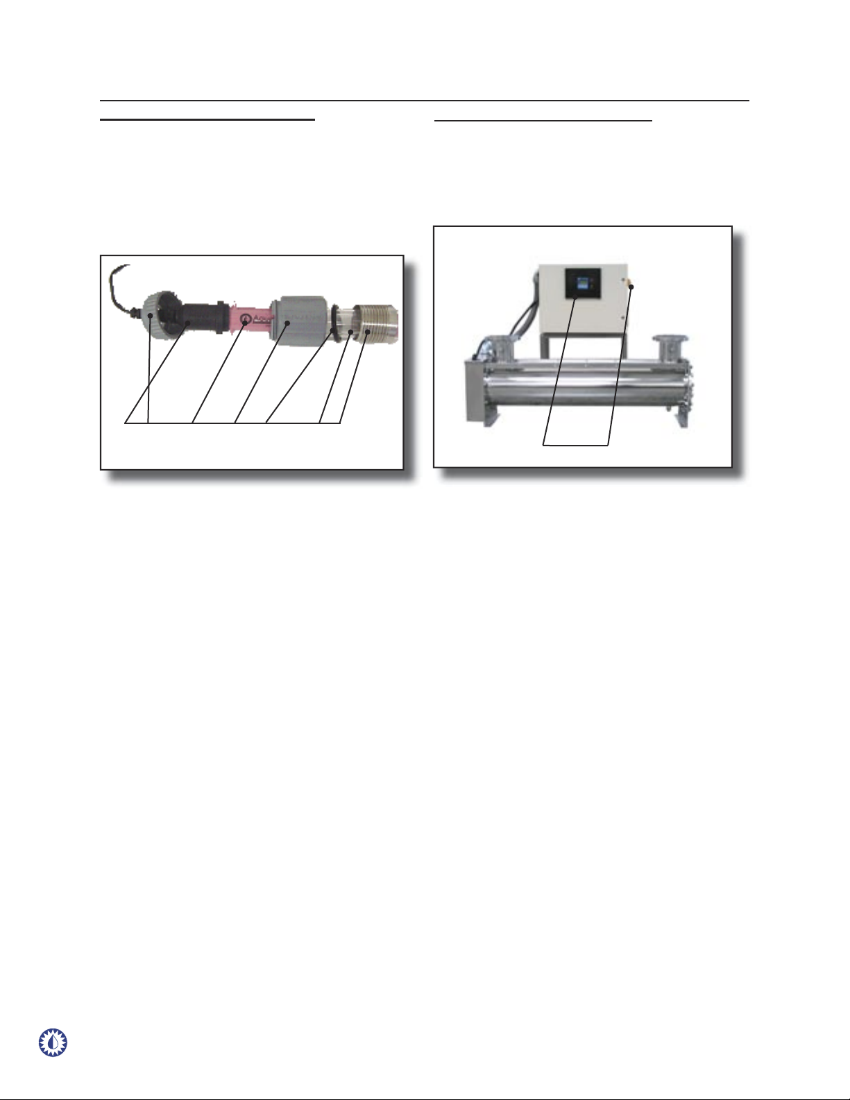
INSTALLATION
INSTALLATION GUIDELINES
The following are the guidelines and procedures for installing
the SCD-H Series.
LOCATION
Install the UV treatment unit in a horizontal position in a
sheltered, well ventilated area. Ambient temperatures
surrounding the unit should be between 35° (2°C) and
100°F (38°C).
Operating water temperature should be between 40°F
(4°C) to 80°F (27°C).
Protect the equipment from the environment. Do not
expose the equipment to direct water spray.
As an ultraviolet UV treatment unit does not introduce
any chemical residue within the water, it is desirable to
install the unit as close as possible to the point-of-use in
order to avoid potential recontamination by discharge
pipes, fi tting, etc.
The base of the UV treatment unit should be mounted
on suitable support to avoid undue strain on the unit
or related pipes and fi ttings.
Allow suffi cient service access clearance, at least 72”
(183 cm) of clearance on the lamp-changing end of the
unit. At the opposite end, there should be a minimum
of 24” (61 cm) of clearance for maintenance. Refer
to mechanical drawings. Clearance for servicing the
electrical cabinet should be allowed.
A.
B.
C.
D.
E.
F.
Should your requirements differ, please contact your local
Aquafine® representative or Aquafine® Customer Service.
ELECTRICAL POWER
The power requirements for each unit depends on
the number and type of lamps used in the treatment
chamber. The overall power consumption of each
unit is indicated on the equipment nameplate decal
on the unit. The unit’s circuit breaker, or main fuse,
provides primary over-current protection. Refer to
wiring diagram.
UV Performance is line voltage sensitive. Line voltage
should be ±5% of rating shown on the electrical
nameplate decal. Voltage outside these limits will affect
the performance of the UV equipment.
Control wiring should reference the appropriate wiring
diagram. Control wiring is based upon customer
requirements and installed options.
A.
B.
C.
NOTE: It is imperative that the unit be properly grounded for
safe and proper operation. FAILURE TO PROPERLY GROUND
THE UV TREATMENT UNIT AUTOMATICALLY VOIDS ALL
EQUIPMENT WARRANTY.
PLUMBING
Limit overhead piping load to 25lbs (11.3kg), for 2”
& 3”, 50lbs (23kg), for 4” and 75lbs (34kg), for 6”
or above. Additional bracing and supports should
be installed on any additional piping and valves in
order to reduce the stress on the treatment chamber
Inlet/Outlet nozzles.
Verify the location is free from vibration, which could be
caused by proximity to heavy equipment and the erratic
or improper pumps. Excessive vibration will damage
internal electrical components and cause premature
failure of the UV lamps.
Each unit has been designed with a 1/2” drain
connection. Install a drain valve and pipe to drain.
Install sample port valves, if equipped.
If your piping system is subject to impulse pressure
resulting in a “water hammer” condition, a surge tank
or other means must be provided to remove this
condition; otherwise the extreme momentary pressure
may rupture and fracture the quartz sleeves.
All units are rated for a maximum operating pressure
of 150psig (10.3 bar).
Ultra pure water users have reported that over time,
exposure to ultraviolet light may photochemically
degrade nonmetallic piping materials, including
most or all fl uoro-polymers, resulting in a material
breakdown and/or structural failure. Should your water
application and piping material be so classifi ed, we
recommend that you install “UV light traps” to isolate
any susceptible material from direct exposure to the
ultraviolet light. Install the UV light trap to the inlet/outlet
of the UV treatment chamber prior to the connection
of any non-metallic piping.
Provide isolation valves on the inlet and outlet nozzels.
A.
B.
C.
D.
E.
F.
G.
H.
During service and maintenance, the electrical power
must be removed.
D.