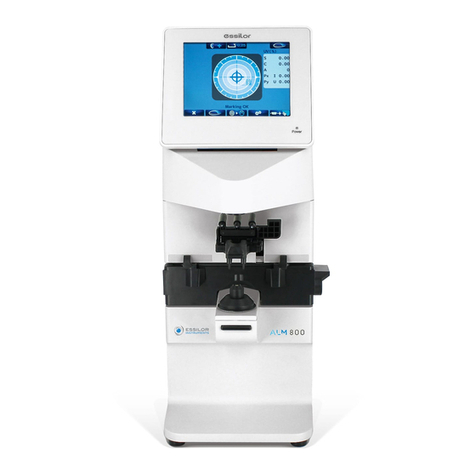
Essilor Instruments ALM 500 User manual

User Guide
Auto lensmeter ALM 500
Version 1


3
Introduction
IntroductionIntroduction
Introduction
This device is aims to measure S, C, A and prism refractive power of the framed lens and contact
lens.
About This Manual
About This ManualAbout This Manual
About This Manual
Please read this manual thoroughl so
Please read this manual thoroughl so Please read this manual thoroughl so
Please read this manual thoroughl so that safe and effective operation is ensured.
that safe and effective operation is ensured.that safe and effective operation is ensured.
that safe and effective operation is ensured.
(1) The information contained in this manual is subject to change without notice.
(2) While reasonable efforts have been made in the preparation of this document to ensure its
accurac , ou should contact our local distributor immediatel if an queries arise due to
editorial errors or omissions etc.
(3) If finding an imperfect collating or missing pages, contact our local distributor for
replacement.
This manual contains important contents to prevent users or others from harms and to use this
device safel .
Read this manual after understanding the s mbols below and follow the instructions in use
Warning
WarningWarning
Warning
This s mbol indicates that mishandling as a result of
failure to compl with the indications can result in
“personal death” or “serious injur ”.
Denote general ban or prohibition.
General mandator action.
NOTE
NOTENOTE
NOTE
Additional information which is important to the text or
useful/ convenient to know.
The number on the left is the lower limit and the one on
the right is the upper limit of the temperature.
The number on the left is the lower limit and the one on
the right is the upper limit of the humidit .
Avoid direct sunlight.
%
90%
10%
This manual contains the information about basic operation, inspection
and maintenance etc. of ALM500.
40℃
5
℃

4
Safet Consideration
General Cautions
General CautionsGeneral Cautions
General Cautions
It affects its measurement accurac if fingerprints or dust etc. are on the optical components such
as glass parts under the lens stand.
Do not touch them with hands, and avoid dust.
If fingerprints or dust are adhered on the optical parts such as a lens etc., wipe it gentl with a soft
cloth.
Observe the following environmental conditions for use, storage and transportation.
Avoid installation near TV or
radio. The reception can be
disturbed b electrical noise.
If liquid is spilled on this device or a foreign substance is entered in it, unplug the power cord and
contact our local distributor.
Turn off the power immediatel and contact our local distributor if malfunction (noise, smoke
etc.) occurs. It can result in fire or injur if ou keep using it.
Do not attempt to disassemble it. It can result in malfunction or fire.
If malfunction occurs, do not touch the inside of this device. Unplug the power cord and contact
our local distributor.
Use
Storage
Transportation
55℃
-10℃
70℃
-
4
0
℃
%
95%
10%
%
95%
10%
%
95%
30%
No Dew Condensation
40℃
5℃

5
Contents
Introduction ............................................................................................................................................ 1
About This Manual................................................................................................................................. 1
Safet Consideration .............................................................................................................................. 2
1.
Accessories ......................................................................7
2.
Device ..........................................................................8
2.1 General Description of Device.............................................................. 8
2.2 Parts Identification ....................................................................... 8
3.
Instructions for Use .............................................................10
3.1 Installation ............................................................................. 10
3.2 Connection/ Wiring ...................................................................... 11
3.3 Maintenance/ Inspection ................................................................. 11
3.4 Disposal ................................................................................ 12
4.
Measurement Screen ............................................................13
4.1 Description of Measurement Screen ....................................................... 13
4.2 Preparation for Measurement............................................................. 14
4.2.1
4.2.14.2.1
4.2.1
Device Setting
Device SettingDevice Setting
Device Setting ........................................................................ 14
4.2.2
4.2.24.2.2
4.2.2
Setup (Device Setting) Screen .......................................................... 14
4.2.3
4.2.34.2.3
4.2.3
ID Screen ............................................................................ 16
4.2.4
4.2.44.2.4
4.2.4
Data Output Screen ................................................................... 17
4.2.5
4.2.54.2.5
4.2.5
Data/Time Screen ..................................................................... 18
4.2.6
4.2.64.2.6
4.2.6
Default Setting Screen................................................................. 18
5.
Operating Instructions of Device..................................................19
5.1 Lens Holder ............................................................................ 19
5.2 Lens Plate .............................................................................. 19
5.3 Marking Lever.......................................................................... 20
5.3.1
5.3.15.3.1
5.3.1
Operating Instructions
Operating InstructionsOperating Instructions
Operating Instructions ................................................................ 20
5.3.2
5.3.25.3.2
5.3.2
Replacement of Marking Pen
Replacement of Marking PenReplacement of Marking Pen
Replacement of Marking Pen ........................................................... 21
5.4 Printer ................................................................................. 22
5.4.1
5.4.15.4.1
5.4.1
Operating Instructions
Operating InstructionsOperating Instructions
Operating Instructions ................................................................ 22
5.4.2
5.4.25.4.2
5.4.2
Installation and Replacement of Printer Paper
Installation and Replacement of Printer PaperInstallation and Replacement of Printer Paper
Installation and Replacement of Printer Paper ........................................... 23
5.5 Replacement of Fuse ..................................................................... 23
6.
Measurement ...................................................................25
6.1 Checkup before Measurement ............................................................ 25
6.2 Measurement of Single Lens ............................................................. 26
6 . 3 Measurement of Framed Lens ......................................................... 27
6.4 Measurement of Multifocal Lens .......................................................... 28
6.5 Measurement of Progressive Lens ......................................................... 29
6.6 Measurement of Contact Lens ............................................................ 32
6.6.1
6.6.16.6.1
6.6.1
Preparation.......................................................................... 32
6.6.2
6.6.26.6.2
6.6.2
Measurement Procedure ............................................................... 32
7.
Marking........................................................................33
7.1 Lens without Astigmatism ............................................................... 33
7.2 Lens with Astigmatism .................................................................. 33
7.3 Marking of Prism Lens................................................................... 34
8.
Other Functions ................................................................35
8.1 Auto Memor Function................................................................... 35

6
8.2 Power Saving Function .................................................................. 35
9.
Error Messages ................................................................ 36
9.1 T pes .................................................................................. 36
9.2 Error Handling Procedure................................................................ 37
10.
Storage ........................................................................ 38
11.
Specification ................................................................... 39
12.
EMC (Electromagnetic Compatibilit ) ............................................ 40

7
1.
1.1.
1. Accessories
AccessoriesAccessories
Accessories
Power cord: 1
(2.5m)
Printer paper: 1
(Width: 58mm) Operation manual: 1
Dust cover: 1 Contact lens stand: 1
Use the accessories specified b us.
The printer paper is the thermal paper roll.
Avoid direct sunlight, high humidit and high temperature at the time of storage.

8
2.
2.2.
2. Device
DeviceDevice
Device
2.1
2.12.1
2.1 General Description of Device
General Description of DeviceGeneral Description of Device
General Description of Device
This device aims to take the measurements of S, C, A, prism refractive power and optical
axis coordinate of unprocessed lens, processed framed lens and contact lens, and to put dots
on them to find its axis.
As an external feature, the angle of the LCD can be changed.
Refer to “3. Instructions for Use” about the operating precautions of this device.
2.2
2.22.2
2.2 Parts Identification
Parts IdentificationParts Identification
Parts Identification
Operation switch
Pilot lamp
Marking lever
Lens holder
Communication
connector
Power inlet
(with fuse holder)
LCD
Lens stand
Lens plate lever
Lens plate
Memor / ADD switch
Printer
Power switch

9
LCD
Color LCD (640X480 dots)
User-friendl LCD which is adjustable verticall within operating range (60°)
Operation switch
Feather touch sensor button in consideration of interaction with screen and interface
Pilot lamp
Indicate ON (light is on)/ OFF (light is off) and power saving mode (blinking).
Marking lever/ lens holder
The marking lever and lens holder are integrated.
・Marking lever: presses the lever down and put the dots.
・Lens holder: fixes the framed glass on the lens stand b moving the lever up and down.
Lens stand
Takes a measurement b placing the framed lens on the lens stand
Lens plate
The plate to be reference of the c lindrical axis and the specified direction of the prism
For the framed lens, take a measurement so as that the lens frame contacts with the lens plate.
Lens plate lever
Moves the lens plate back and forth.
Memor / ADD switch
Stores the measurement values of the short focus lens, multifocal lens and contact lens on the
measurement screen in memor .
Freezes the displa of the measurement values and stores them in memor .
For the measurement screen of the progressive lens, this switch is to set the near and far points
in case of the manual measurement.
Communication connector
Transfers the measurement data to another equipment or PC.
Power inlet
Connects the accompanied power cord for power suppl
Power suppl switch
Turns on/off the device
Printer
Prints out the measurement values.

10
3.
3.3.
3. Instructions for Use
Instructions for UseInstructions for Use
Instructions for Use
3.1
3.13.1
3.1 Installation
InstallationInstallation
Installation
(1)
Do not expose the device to sunlight or bright light from other
sources.
(2)
Do not install the device in places where either dust
or rubbish ma accumulate.
Also, the environments with extremes in heat and
humidit should be avoided.
In case of using the device, ensure to compl with the
environmental conditions of unpacking and usage
before starting a measurement.
・Temperature range for use: 5℃ to 40℃
・Humidit range for use: 30%HR to 95%HR
・Temperature range for storage: -10℃ to 55℃ (No dew condensation)
・Humidit range for storage: 10%HR to 95%HR (No dew condensation)
(3)
Keep awa from inflammable or explosive gases as
well as storage area of the medical supplies and
chemicals.
(4)
Keep awa from the sites that experience strong
vibrations or sudden shocks.
(5)
The device might be broken if it falls down. Also, it
might cause injur if dropping it. Therefore, do not
store it at an unstable place or in high, ‘out of reach’
place.
(6)
Keep this device awa from water (liquid).
・Degree of protection: IP20
Take extra caution to avoid strong light
because
it ma cause the failure of measurement.
NOTE
NOTENOTE
NOTE
Dust
DustDust
Dust
Gas
GasGas
Gas

11
3.2
3.23.2
3.2
Connection/ Wiring
Connection/ WiringConnection/ Wiring
Connection/ Wiring
(1)
The earth cable of the power code should be connected to the earth terminal.
(2)
Avoid damaging the power cord (such as bending it in an extremel small size, pulling,
placing a heav object on it etc.). Also, do not fabricate the cord.
(3)
When the power cord is damaged, (breaks, damage of cover etc.), replace it to the new one.
Fire or electric shock ma occur if ou keep using it.
(4)
Insert the power cord firml into the outlet and device. If not, fire or electric shock ma occur.
(5)
Keep the power cord clean without an dust or oil etc. on it. The dirt terminal ma cause
malfunction or fire.
(6)
When the power cord gets hot after use, check for the dirt of the terminal unit. If ou find no
dirt, replace the power cord to the new one. Fire or electric shock ma occur if ou keep using
it.
(7)
Use it with the correct power-suppl voltage. Fire or electric shock ma occur if using it with
more than the rated suppl voltage.
(8)
Alwa s hold the plug when plugging or unplugging the power cord.
(9)
Do not touch the plug with wet hands. You ma get an electric shock.
(10)
If the device is not used for a long time, unplug the power cord from the outlet.
3.3
3.33.3
3.3 Maintenance/ Inspection
Maintenance/ InspectionMaintenance/ Inspection
Maintenance/ Inspection
(1)
This is the precision optical device. Make sure not to mishandle or
drop it.
(2)
Do not touch
Do not touchDo not touch
Do not touch or allow dust to adhere on the optical parts (i.e.
lenses), as the measurement accurac could be adversel affected
b fingerprints and dust etc.
When fingerprints or dust are adhered onto the optical parts,
gentl wipe them with the accompan ing dust cloth or a soft
cloth. In this instance, make sure not to scratch them.

12
(3)
If the main unit cover or operation panel is dirt , gentl wipe it
with a dr cloth. For hard to remove stains, a damp cloth or
neutral cleanser is recommended.
(4)
If the device is not used for an length of time, unplug the power cord.
(5)
When the device is not in use, protect it with the
accompan ing dustproof cover. The measurement
accurac could be affected b dust.
(6)
Never attempt to fix or remodel the device. When the
device fails to function properl , do not touch the inside
do not touch the insidedo not touch the inside
do not touch the inside.
Contact us or our local distributor.
3.4
3.43.4
3.4 Disposal
DisposalDisposal
Disposal
Dispose this device according to the regulations of each local government and rec cle plan.
Inappropriate disposal affects the environment.
Avoid using organic solvent such
as thinner which
ma damage the water based paint finish or device.

13
4.
4.4.
4. Measurement Screen
Measurement ScreenMeasurement Screen
Measurement Screen
4.1
4.14.1
4.1 Description of Measurement Screen
Description of Measurement ScreenDescription of Measurement Screen
Description of Measurement Screen
※The displa of the measurement screen reflects the setting and condition of the device.
The functions of the operation switches under the monitor are correspondent to the icons
displa ed at the bottom of the screen.
At the time of normal measurement, the are correspondent to the icons shown below.
【Explanation about switches】
Name of switch Icon Description of function
Bottom of screen: 5
Bottom of screen: 5Bottom of screen: 5
Bottom of screen: 5
Function setting
switch
Switches to the Setup (device setting)
screen.
Measurement
selection switch Switches to multifocal lens
measurement from single focus lens.
Unprocessed lens/
framed lens
selection switch
Selects unprocessed, left or right lens.
Clear switch Deletes measurement values stored in
memor .
Measurement
value output
switch
Prints out measurement result, outputs
data from RS232C or both.
Lens stand unit: 1
Lens stand unit: 1Lens stand unit: 1
Lens stand unit: 1
Memor / ADD
switch No icon Stores measurement values in memor
and take a measurement of ADD.
Measurement screen of single focus lens, multifocal lens and contact lens
Displa of alignment
condition or error
message
T pe of lens:
Left/ right/ single
Axis mark
Cross cursor
Measurement setting

14
4.2
4.24.2
4.2 Preparation for Measurement
Preparation for MeasurementPreparation for Measurement
Preparation for Measurement
4.2.1
4.2.14.2.1
4.2.1 Device Setting
Device SettingDevice Setting
Device Setting
This device is read for use with the standard mode but the setting can be changed easil
as needed.
Switch to the Setup (setup of device) screen b pressing at the bottom of
screen.
4.2.2
4.2.24.2.2
4.2.2 Setup (Device Setting) Screen
【1/3 screen】
【2/3 画面】
Item Description of Function
C l
C lC l
C l
Selects sign for C l:-
--
-
/ +
++
+
/ ±
±±
±
Selects step to displa measurement value
Step
StepStep
Step
0.25
0.250.25
0.25
/ 0.12
0.12 0.12
0.12 / 0.01
0.010.01
0.01
Sets auto detection of progressive lens Auto
Auto Auto
Auto
Prog.
Prog.Prog.
Prog.
On
OnOn
On
/ Off
OffOff
Off
Selects lens to be measured
Lens
LensLens
Lens
Normal
NormalNormal
Normal: Framed lens
H CL
H CLH CL
H CL: Hard contact lens
S CL
S CLS CL
S CL: Soft contact lens
Sets auto memor at the time of “Marking OK” Auto
Auto Auto
Auto
Memor
MemorMemor
Memor
On
OnOn
On
/ Off
Off Off
Off
Selects auto/ manual memor of far and near
points
ADD
ADD ADD
ADD
Measure
MeasureMeasure
Measure
F/N.AT
F/N.ATF/N.AT
F/N.AT: Stores both near and far points
automaticall
N.AT
N.ATN.AT
N.AT: Stores onl near point automaticall
Ma
MaMa
Manual
nualnual
nual: Stores data manuall
Change of switch function
Change of switch functionChange of switch function
Change of switch function
The functions of each switch are changed on the menu screen.
The icons corresponding to each switch are displa ed at the bottom of the screen.
Operate each switch in accordance with the displa .
:Moves the cursor downward at each setting item
:Moves the cursor upward at each setting item
:Goes to a further page of Setup ( → → )
:Selects the item in each setting item. The cursor is moved horizontall .
:Returns to the measurement screen
NOTE
NOTENOTE
NOTE

15
【2/3 screen】
Item Description of Function
Selects language displa ed on
screen
Language
LanguageLanguage
Language
English/ French/ Spanish/ Italian/
Portuguese/ German/ Chinese
Brightness
BrightnessBrightness
Brightness
Sets brightness of screen
(50% to 100%)
Sound Mute
Sound MuteSound Mute
Sound Mute
Sets On/Off of sound at the time of
operating switches
Data Output
Data OutputData Output
Data Output
Switches to Data Output
Data OutputData Output
Data Output screen
Date
DateDate
Date/Time
/Time/Time
/Time
Switches to Date/Time
Date/TimeDate/Time
Date/Time screen
Default
Default Default
Default
Setting
SettingSetting
Setting
Displa s the Setup items changed
from default and changes the setting
back to the default b pressing
.
Item Description of Function
Sets displa of ADD value and
assessment graph on progressive lens
measurement screen
Prog.
Prog. Prog.
Prog.
Graph
GraphGraph
Graph
On
OnOn
On / Off
OffOff
Off
Sets printing of ADD value and
assessment graph after measuring
progressive lens
Graph
Graph Graph
Graph
Print
PrintPrint
Print
On
OnOn
On / Off
OffOff
Off
Selects displa of prism value and unit
to be displa ed
Prism
PrismPrism
Prism
Off
OffOff
Off: No displa X
XX
X-
--
-Y
YY
Y: X-Y displa
P-B: Prism value - base direction
Displa s prism value of X
XX
X-
--
-Y
YY
Y direction
in mm
Prism(mm)
Prism(mm)Prism(mm)
Prism(mm)
On
On On
On / Of
OfOf
Off
ff
f
Abbe
AbbeAbbe
Abbe
Selects Abbe number:
20 / 30 / 40 / 50 / 60
20 / 30 / 40 / 50 / 6020 / 30 / 40 / 50 / 60
20 / 30 / 40 / 50 / 60
Selects measurement wavelength
Ra
RaRa
Ra
e
e e
e line / d
dd
d line
Selects time to activate standb mode
Stand
StandStand
Standb
bb
b
Off
Off Off
Off / 3
33
3min / 5
55
5min / 10
1010
10min
2
22
2
3
33
3
【3/3 screen】

16
4.2.3
4.2.34.2.3
4.2.3 ID Screen
This screen is to create the data for printing out the distributor’s name or message on the printout.
(1)
(1) is the screen for writing the information.
(2) is the screen for changing or erasing the
information.
How to input
How to inputHow to input
How to input
In the Screen (1), select the characters with
and enter them with
.
An changes made will overwrite the original
characters.
The maximum number of characters is 44
(22 characters X 2 lines).
In case of changing the characters, move the
cursor to the one changed
b pressing
with holding the Memor /
ADD switch. Return to Screen (1) and select
the character to be input with
and press .
How to delete
How to deleteHow to delete
How to delete
In case of deleting the characters, move the
cursor to the one deleted with
and press .
The screen shown on the left appears b
selecting “ID Screen”.
(2) While Memor /ADD switch is held
The cursor in moves b pressing
the arrows.
The cursor in
moves while the
Memor /ADD switch is held
The
cursor in
moves while the
Memor /ADD switch is held

17
4.2.4
4.2.44.2.4
4.2.4 Data Output Screen
This screen is to set the communication parameter for outputting the measurement values to the
externall -connected PC etc.
The measurement values and data created on the “ID screen
ID screenID screen
ID screen” are output b selecting “RS
RSRS
RS232C
232C232C
232C” or
“Both
BothBoth
Both” of “Data Output
Data OutputData Output
Data Output” on the Setup screen.
Setting of Communication to PC etc
Setting of Communication to PC etcSetting of Communication to PC etc
Setting of Communication to PC etc.
..
.
The communication from RS232C port is set on “Data Output
Data OutputData Output
Data Output”.
【Setting screen in case of outputting from RS232C 】
【Example of connection】
D-Sub 9pin
(male) D-Sub 9pin
(female)
Lensmeter Connection PC
1
1
2
2
3
3
4
4
5
5
6
6
7
7
8
8
9
9
Use the straight cable (D-sub 9 pin: male/ D-sub 9: female) as the connection cable at the
time of outputting the measurement values b using the RS232C.
※ Contact our local distributor if ou have an thing unclear or an questions regarding
operation and connection.
Item Description
Setting of output destination
Print
PrintPrint
Print
RS232C
RS232CRS232C
RS232C
Both
BothBoth
Both
Output Device
Output DeviceOutput Device
Output Device
Device
Device Device
Device
printer
printerprinter
printer
RS232C
RS232C RS232C
RS232C
terminal
terminalterminal
terminal
Both
BothBoth
Both
Setting
“Off
OffOff
Off” “On
OnOn
On”
Auto Comm
Auto CommAuto Comm
Auto Comm
B pressing “Output”
switch on measurement
screen
Measurement values
are output
continuousl
Band
BandBand
Band
Rate
RateRate
Rate
(Communication
speed)
Select from 115200
115200115200
115200, 38400
3840038400
38400 or 9600
96009600
9600.
The output content is same with the one of the printout.
However, the graph at the time of progressive lens measurement is not output.
NOTE
NOTENOTE
NOTE
D-Sub: 9Pin (male)
5 4 3 2 1
9 8 7 6
Use a shield wire for a connecting cable to protect the output data from noise.
NOTE
NOTENOTE
NOTE
D-Sub: 9Pin (female)
1 2 3 4 5
6 7 8 9
In case of output from RS232C, the data is output
onl in English regardless of language setting.
NOTE
NOTENOTE
NOTE

18
4.2.5
4.2.54.2.5
4.2.5 Data/Time Screen
The screen to set the date and time for printout and communication output
(1)
Select the item to be changed with
and set the detail with .
“Date Form
Date FormDate Form
Date Form”:YMD
YMD YMD
YMD → Year, Month, Da
“Date Form
Date FormDate Form
Date Form”:DMY
DMY DMY
DMY → Da , Month, Year
“Date Form
Date FormDate Form
Date Form”:MDY
MDY MDY
MDY → Month, Da , Year
Date: change of date
Date: change of dateDate: change of date
Date: change of date
Select “Date” with .
Move the cursor to the item to be changed
with .
While the Memor / ADD switch is held, the
Screen (2) is displa ed. Make changes with
.
Time
TimeTime
Time:
::
: change of time
change of time change of time
change of time
Select “Time” with .
Move the cursor to the item to be changed with
.
While Memor / Add switch is pressed, the
Screen (2) is displa ed. Make changes with
.
4.2.6
4.2.64.2.6
4.2.6 Default Setting Screen
The screen to change the setting of the device back to the default
The list of the items changed from the default is also displa ed.
Press if ou wish to change the setting back
to the default.
Press if ou do not wish to change the setting
back to the default. It goes back to the measurement
screen after pressing either switch.
(2) While the Memor / ADD switch is pressed

19
5.
5.5.
5. Operating Instructions of Device
Operating Instructions of DeviceOperating Instructions of Device
Operating Instructions of Device
5.1
5.15.1
5.1 Lens Holder
Lens HolderLens Holder
Lens Holder
(1)
Raise the lever to the operational
direction until it is unlocked.
(2)
Lower the lens holder slowl and fix
the lens.
5.2
5.25.2
5.2 Lens Plate
Lens PlateLens Plate
Lens Plate
The lens plate is the reference of the c lindrical axis.
Place the framed lens and rotate the lens plate lever to the direction of the arrow so that the
bottom of the lens touches the lens plate. After that, lower the lens holder and fix the lens.
(1)
Operational direction
(2)
Do not give strong impact to a lens when lowering the lens holder.
When rising the lens holder, make sure to move to the top.
Lens p
late
Lens plate lever

20
5.3
5.35.3
5.3 M
MM
Marking Lever
arking Leverarking Lever
arking Lever
5.3.1
5.3.15.3.1
5.3.1 Operating Instructions
Operating InstructionsOperating Instructions
Operating Instructions
(1)
Turn and lower the marking lever..
(2)
Place the tips of the marking pens on the lens
surface softl .
(3)
Release the finger after marking.
(4)
The marking lever returns to the initial position.
Marking lever
Do not mark several times at the same point.
The marking pen ma be worn out quickl .
Avoid the followings since the ma damage the tips of the marking pens.
・ Perform marking roughl
・ Operate the marking lever without a lens set.
・ Touch a tip of the marking pen during cleaning.
This manual suits for next models
1
Table of contents
Other Essilor Instruments Measuring Instrument manuals
