Aquametro Contoil DFM 8EDM Service manual

VD 4-565 def 09.2012
Montage- und Bedienungsanleitung Seite 2 - 7
Mounting and operating instructions Page 8 - 13
Manuel de montage et d'utilisation Page 14 - 23
CONTOIL
®
DFM 8 E D M
Inhaltsverzeichnis
Sicherheitsanweisungen 2
- Bestimmungsgemässe Verwendung
- Installation, Inbetriebnahme und Betrieb
- Betriebssicherheit
- eräteeinsendung
- Hinweise zu Sicherheitsbestimmungen und -symbolen
Konfigurationsübersicht 3
- Schematische Konfigurationsdarstellung
- Installationshinweise
- Zu Ihrer eigenen Sicherheit...
Anschliessen des CONTOIL®DFM 8EDM an
einen Flottenmanager oder ein PS-System 4
- Funktionsbeschreibung
- Installationsbeschreibung
- Elektrische Verbindung
Inbetriebnahme 5
Was tun, wenn das erät nicht funktioniert? 5
Elektrische Verbindungen und Spezifikationen 5
- Erläuterung der Kabel
Spezifikation und technische Angaben 6
Abmessungen 7
Bestellinformationen 7
arantiehinweise 7
Table o contents
Safety instructions 8
- Designed use
- Installation, commissioning and operation
- Operational safety
- Return of the instruments
- Notes on safety conventions and icons
Configuration overview 9
- Schematic of a configuration
- Installation advices
- For your security...
CONTOIL®DFM 8EDM to a fleet manager or to a PS system 10
- Function description
- Installation description
- Electrical connection
Startup (commissioning) 11
What is to do if it is not functioning? 11
Electrical connections and specifications 11
- Explanation of the wires
Specification and technical data 12
Dimensions 13
Ordering information 13
Warranty information 13
Table des matières
Consignes de sécurité 14
- Utilisation conforme
- Installation, mise en service et fonctionnement
- Sûreté opérationnelle
- Retour des instruments
- Remarque sur les dispositions et symboles de sécurité
Aperçu de la configuration 15
- Schéma de configuration
- Conseils d'installation
- Pour votre sécurité...
Raccordement d'un CONTOIL®DFM 8EDM à
un gestionnaire de flotte ou à un PS 16
- Description du fonctionnement
- Description de l'installation
- Branchements électriques
Mise en service 17
Que faire si l'appareil ne fonctionne pas? 17
Branchements et spécifications électriques 17
- Explication des câbles
Spécifications et caractéristiques techniques 18
Dimensions 19
Informations pour la commande 19
Informations sur la garantie 19

2CONTOIL®DFM 8EDM
Sicherheitsanweisungen
Bestimmungsgemässe Verwendung
Dieses erät ist für die Erfassung, Berechnung, Darstellung und Versendung von Informationen ausgelegt. Eine unsachgemässe oder nicht
bestimmungsgemässe Verwendung kann dazu führen, dass die Betriebssicherheit des eräts nicht mehr gewährleistet ist. Der Hersteller
übernimmt für daraus resultierende Schäden keine Haftung.
Installation, Inbetriebnahme und Betrieb
Die Installation, der Anschluss an die Stromversorgung, die Inbetriebnahme und die Wartung des eräts müssen durch geschultes, quali-
fiziertes Fachpersonal erfolgen, das zur Ausführung solcher Arbeiten berechtigt ist. Das jeweilige Fachpersonal muss diese Betriebsanlei-
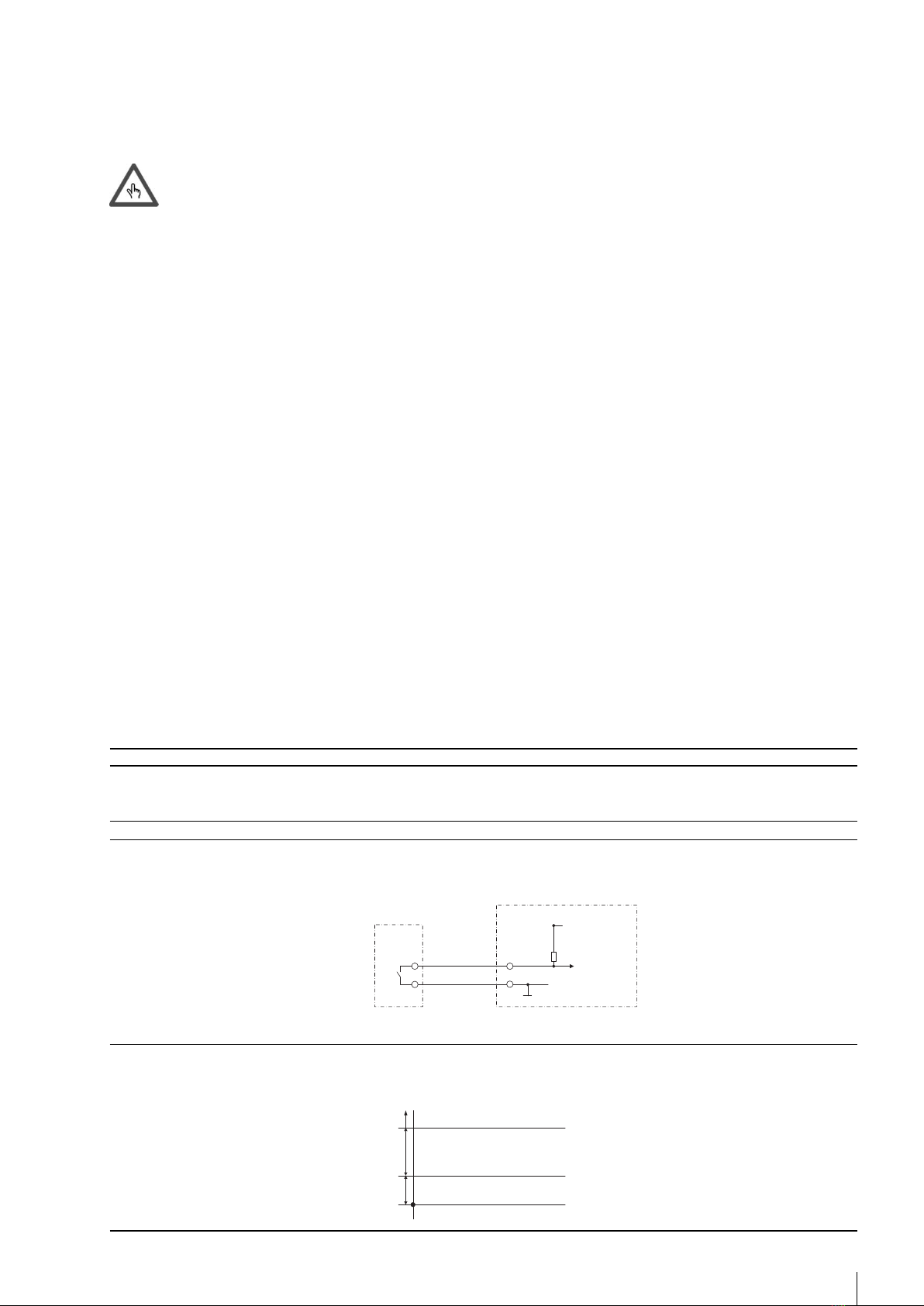
tung gelesen und verstanden haben und die enthaltenen Anweisungen befolgen. Der Monteur muss sicherstellen, dass das Messsystem
gemäss den Schaltplänen korrekt verkabelt ist. Unterbrechen Sie vor der elektrischen Installation die Stromversorgung und stellen Sie si-
cher, dass niemand diese ohne Ihre Zustimmung wieder herstellen kann.
Beachten Sie folgende Punkte:
• Spannung, Betriebsdaten
• Maximale Übertragungslänge
• Kabelquerschnitt und -länge
• Umgebungstemperatur und Einbauposition
Betriebssicherheit
Der Hersteller behält sich das Recht vor, ohne Vorankündigung Änderungen an den technischen Daten vorzunehmen. Bei Ihrem Händler vor
Ort erhalten Sie aktuelle Informationen und neue Versionen dieser Betriebsanleitung.
Geräteeinsendung
Bevor ein erät beispielsweise aufgrund einer Reparatur- oder Kalibrierung an Aquametro eingesendet wird, müssen folgende Schritte durch-
geführt werden:
• Legen Sie dem erät immer ein vollständig ausgefülltes „Reparaturformular“ bei. Nur dann kann Aquametro ein eingesendetes erät
transportieren, untersuchen und reparieren.
Hinweise zu Sicherheitsbestimmungen und -symbolen
Die eräte sind so konzipiert, dass sie die neuesten Sicherheitsanforderungen erfüllen. Sie wurden getestet und in einem Zustand ausge-
liefert, der einen sicheren Betrieb gewährleistet. Bei unsachgemässer oder nicht bestimmungsgemässer Verwendung können die eräte
jedoch eine efahrenquelle darstellen. Achten Sie daher immer besonders auf die in dieser Anleitung durch folgende Symbole dargestell-
ten Sicherheitshinweise:
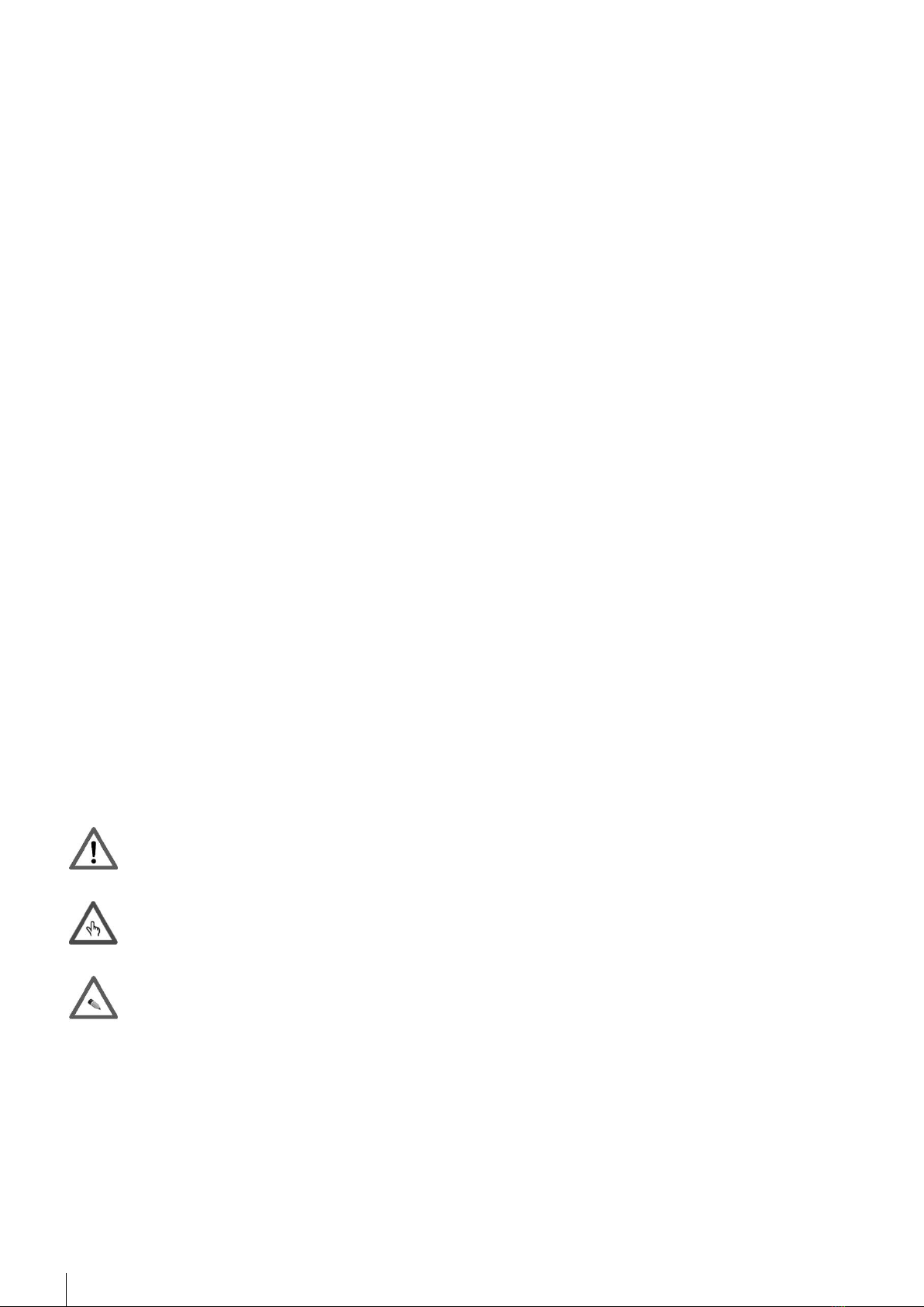
Achtung!
„Achtung“ weist auf eine Handlung oder Massnahme hin, die bei falscher Ausübung zu Verletzungen oder einem
Sicherheitsrisiko führen kann. Befolgen Sie stets die Anweisungen und gehen Sie mit Vorsicht vor.
Vorsicht!
„Vorsicht“ weist auf eine Handlung oder Massnahme hin, die bei falscher Ausübung zu einer fehlerhaften Funktionsweise
oder zur Zerstörung des eräts führen kann. Befolgen Sie stets die Anweisungen.
Hinweis!
„Hinweis“ weist auf eine Handlung oder Massnahme hin, die sich bei falscher Ausübung indirekt auf den Betrieb
auswirken oder eine unerwartete Reaktion des eräts auslösen kann.

3
CONTOIL®DFM 8EDM
Kon igurationsübersicht
Schematische Konfigurationsdarstellung
Installationshinweise
• Die Durchflussmesser müssen immer durch einen Kraftstofffilter geschützt werden. Die max. Maschenweite hängt von der Nennweite
der Durchflussmesser ab. Doch der Original-Lkw-Kraftstofffilter ist für alle Durchflussmesser geeignet.
• Beachten Sie, dass sämtlicher Kraftstoff, der den Vorlauf-Durchflussmesser passiert UND nicht vom Motor verbraucht wird, durch den
Rücklauf-Durchflussmesser in den Tank zurückfliessen MUSS.
• Eine Leck-Leitung der Einspritzdüsen MUSS an die Rücklaufleitung geführt werden und vor dem Rücklauf-Durchflussmesser ange-
schlossen werden.
• Wenn die Durchflussmesser mit einem S bzw. einem R gekennzeichnet wurden, installieren Sie den S-Durchflussmesser in der
VORLAUFLEITUN und den R-Durchflussmesser in der RÜCKLAUFLEITUN .
• Die Pfeile auf den Durchflussmesser müssen in Flussrichtung zeigen.
• Die Durchflussmesser müssen frei von aseinschlüssen sein.
• Hochfrequente Druckstösse der Einspritzpumpe auf den Durchflussmesser der Vorlaufleitung müssen vermieden werden (z.B. mithilfe
eines min. zwei Meter langen, gewundenen Schlauchs zwischen dem Durchflussmesser in der Vorlaufleitung und der Einspritzpumpe).
• Montieren Sie den DFM Bordcomputer in der Fahrerkabine am Boden, im oberen Kabinenbereich oder am Armaturenbrett, sodass er
stets leicht zugänglich und ablesbar ist.
• Der DFM-BC kann auch ausserhalb der Fahrerkabine montiert werden (IP66)
• Für eine fachgerechte Montage des Bordcomputers (DFM-BC) empfehlen wir das Befestigungs-Kit (Art.-Nr. 80485).
Zu Ihrer eigenen Sicherheit...
• NEHMEN Sie während Sie fahren KEINE Änderungen der Einstellungen vor. Dies könnte Sie und andere Verkehrs-
teilnehmer in efahr bringen.
• Klemmen Sie während der elektrischen Installation die Batterie des Fahrzeugs ab.
• Seien Sie bei der Trennung der Leitungen vorsichtig (es könnte Treibstoff austreten).
• Prüfen Sie nach der Installation alle Leitungen auf undichte Stellen.
Tank
Motor
Pumpe
Vorfilter
Feinfilter
Mechanische
Einspritzpumpe
CONTOIL®DFM 8EDM
Anschluss an einen Flottenmanager,
ein GPS-Trackingsystem oder
einen Hauptcomputer

4CONTOIL®DFM 8EDM
Anschliessen des CONTOIL®DFM 8EDM an
einen Flottenmanager oder ein GPS-System
Bevor Sie das System elektrisch verbinden, müssen alle gelieferten Komponenten ordnungsgemäss installiert worden
sein. Diese Installation muss von einer berechtigten und zertifizierten Person durchgeführt werden.
Beachten Sie bitte: Eine fehlerhafte Installation kann das DFM-System zerstören und Ihrem Fahrzeug Schäden zufügen.
In diesem Fall übernimmt Aquametro keinerlei Haftung.
Funktionsbeschreibung
• Die Vorlaufleitung beginnt am Tank, läuft dann zum Vorfilter, weiter zur Kraftstoffpumpe, zum Vorlauf-Durchflussmesser, zum Feinfilter
und schliesslich zur Einspritzpumpe.
• Die Einspritzpumpe spritzt die benötige Menge an Treibstoff ein und leitet den Rest über die Rücklaufleitung zurück in den Tank. Auch die
sogenannten „Leckleitungen“ aller Einspritzventile werden in einer Leitung vereint und mithilfe eines T-Stücks mit der Rücklaufleitung
verbunden (siehe schematische Konfigurationsdarstellung).
• Die Rücklaufleitung endet im Tank.
Dies ist lediglich eine allgemeine Beschreibung. Im Einzelfall können Abweichungen vorliegen.
Installationsbeschreibung
Der CONTOIL®DFM 8EDM verfügt über zwei Durchflusskammern: eine Vorlauf- und eine Rücklauf-Kammer. Diese Kammern sind mit ei-
nem „S“ für Supply (Vorlauf) und einem „R“ für Return (Rücklauf) gekennzeichnet. Der Kraftstoffeingang der Kammer ist mit einem Pfeil ge-
kennzeichnet (siehe Bilder).
Montieren Sie den CONTOIL®DFM 8EDM an einem vibrationsfreien Ort am Fahrzeug (NICHT auf dem Motor). Verbinden Sie die Vorlauf-
kammer, sodass sie beidseitig mit der Treibstoffvorlaufleitung verbunden ist. Verbinden Sie die Rücklaufkammer, sodass sie beidseitig mit
der Treibstoffrücklaufleitung verbunden ist. Ziehen Sie alle Verbindungen fest an.
Elektrische Verbindung
Der CONTOIL®DFM 8EDM hat 4 Kabel:
Farbe des Kabels Funktion Hinweis
Weiss 12 - 24 VDC Eingangsspannung 12 - 24 VDC vom DFM-BC oder von einer anderen Quelle.
Wenn Sie eine andere Quelle verwenden, müssen Sie sicherstellen, dass die Spannung
stabil und gefiltert ist.
Braun ND Masse (die gleiche Masse wie die 12 - 24 VDC Quelle verwenden).
rün Open-Drain (out1) Bei enerierung eines Signals wird diese Leitung auf Masse gesetzt.
elb Spannungspegel (out2) Unter 0,8 VDC = kein Signal (Logik 0)
Nicht definierter Bereich zwischen 0,8 - 2,8 VDC
Über 2,8 VDC = Signal (Logik 1)
Schliessen Sie die aufgeführten Kabel gemäss den Anweisungen der Installationsanleitung des Flottenmanagers-System oder PS-Systems
an.

5
CONTOIL®DFM 8EDM
Inbetriebnahme
In diesem Abschnitt setzen wir voraus, dass alle erforderlichen eräte fachgerecht installiert wurden, d.h.:
Das Kraftstoffsystem wurde gemäss den Hinweisen des Motorenherstellers entlüftet und ist leck- und
blasenfrei.
1. Starten Sie den Motor und lassen Sie ihn mit niedriger Drehzahl laufen bis er seinen Betriebszustand erreicht hat
(Kühlwasser zwischen 70 °C - 90 °C).
2. Prüfen Sie in der Aufwärmphase des Motors, ob alle Anschlüsse dicht sind.
Was tun, wenn das Gerät nicht unktioniert?
Kein Signal oder falsche Werte auf dem Flottenmanager oder GPS-System
Prüfen Sie Folgendes:
a. Liegt mindestens eine Spannung von 12 VDC am CONTOIL®DFM 8EDM?
b. Haben Sie das richtige Kabel/den richtigen Signalausgang gewählt? (siehe Elektrische Verbindung)
c. Prüfen Sie, ob die Kabel ordnungsgemäss angeschlossen sind.
d. Wurden alle Einstellungen am Flottenmanager oder PS-System vorgenommen?
e. Funktioniert der Zähler weiterhin nicht?
Wenden Sie sich für weitere Informationen an Ihren Händler vor Ort.
Elektrische Verbindungen und Spezi ikationen
Erläuterung der Kabel
Farbe des Kabels Funktion Hinweis
Weiss 12 - 24 VDC Eingangsspannung 12 - 24 VDC vom DFM-BC oder von einer anderen Quelle.
Wenn Sie eine andere Quelle verwenden, müssen Sie sicherstellen, dass die Spannung
stabil und gefiltert ist.
Braun ND Masse (die gleiche Masse wie die 12 - 24 VDC Quelle verwenden).
rün Open-Drain (out1) Bei enerierung eines Signals wird diese Leitung auf Masse gesetzt.
Das externe erät muss die Spannung liefern (12 - 24 VDC).
Symbolische Darstellung der Funktionsweise.
elb Spannungspegel (out2) Unter 0,8 VDC = kein Signal (Logik 0)
Nicht definierter Bereich zwischen 0,8 - 2,8 VDC
Über 2,8 VDC = Signal (Logik 1)
Signal
kein Signal
nicht definiert
2.8 VDC
0.8 VDC
0 VDC
Externes Gerät
z.B. Flottenmanager
12 - 24 VDC
Masse
Eingangssignal
grün
braun
+
-
CONTOIL®DFM 8EDM
(out 1)

6CONTOIL®DFM 8EDM
Spezi ikation und technische Angaben
• Verbrauchsart: Differenz-Verbrauchsmessung
• Flüssigkeiten: Dieselkraftstoff
Hydraulische Angaben
Artikelnummer 94954
Hydraulikanschluss M14 x 1.5
Nenndruck 16 bar
Mindestflussrate 10 l/h
Durchflussrate 200 l/h
Max. Durchflussrate (für kurze Zeit) 260 l/h
Schutzart IP 66
Betriebstemperatur Betrieb: -20 °C bis +80 °C
Lagerung: -40 °C bis +125 °C
Abmessungen (L x H x B) 143 x 77 x 74 mm
enauigkeit Besser als 1%
Wiederholgenauigkeit ±0.2 %
Maschenweite des Sicherheitsfilters 0.100 mm
Volumen der Messkammer 12.5 ml
ewicht ca. 1,6 kg
Elektrische Angaben
Stromversorgung 12 - 24 VDC
Impuls 1 (out1) Impulsbreite: 20 ms
Max. Impulspause: Min. 122 ms
Impulse/Liter: 80
Impuls 2 (out2) TTL-Logik
Max. Arbeitsstrom (Open-Drain-Ausgang) 50 mA
Max. Ausgangsbetriebsspannung 24 VDC

7
CONTOIL®DFM 8EDM
Abmessungen
Ø 74 mm 143 mm
77 mm
Bestellin ormationen
Beschreibung Artikelnummer
CONTOIL®DFM 8EDM 94954
ewindeverbindungen (PS-Satz DFM und VZD/VZP) 80447
Hinweis: Dieser Artikel wird für alle Anschlüsse insgesamt viermal benötigt.
Garantiehinweise
Alle Produkte von Aquametro gewährleisten eine hohe Qualität und werden unter Einhaltung der ISO 9001 Standards hergestellt. Jeder
einzelne Durchflusssensor wird einem enauigkeitstest unterzogen, dessen Ergebnis in einem Testprotokoll dokumentiert wird. Die Prü-
fanlagen für dieses Verfahren stehen unter ständiger Kontrolle durch Schweizer und deutsche Behörden (METAS und PTB). Die elektronis-
chen Produkte müssen einen eigenen Qualitätstest bestehen. Daher garantiert Aquametro die Produktqualität (perfektes Material, optimale
Verarbeitung und Funktion) für jedes einzelne ausgelieferte Produkt. Weitere Informationen finden Sie in unseren eschäftsbedingungen.
arantie-Ansprüche, welche aus unsachgemässer Installation oder Verwendung hervorgehen, können nicht geltend gemacht werden.

8CONTOIL®DFM 8EDM
Sa ety instructions
Designed use
This unit is designed for acquisition, calculation, displaying and sending datas. Resulting from incorrect use or from use other than that de-
signated, can suspend the operational safety of the devices. The manufacturer accepts no liability for damages being produced from this.
Installation, commissioning and operation
Installation, connection to the electricity supply, commissioning and maintenance of the device must be carried out by trained, qualified spe-
cialists authorised to perform such works. The specialist must have read and understood these Operating Instructions and must follow the
instructions they contain. The installer must ensure that the measuring system is correctly wired in accordance with the wiring diagrams.
Before working on electrical installation, make sure to disconnect the power supply and ensure that nobody can reconnect it without your
permission.
Pay attention to the following points:
• Voltage, operation data
• Maximum transmission length
• Cable cross section, length
• Ambient temperature and mounting position
Operational safety
The manufacturer reserves the right to modify technical data without prior notice. Your local distributor will supply you with current infor-
mation and updates to these Operating Instructions.
Return of the instruments
The following procedures must be carried out before a device requiring repair or calibration, for example, is returned to Aquametro:
• Always enclose a fully completed “Repair Form” with the device. Only then Aquametro can transport, examine and repair a returned
device.
Notes on safety conventions and icons
The devices are designed to meet state-of-the-art safety requirements. They have been tested and left the factory in a condition in which
they are safe to operate. They can, however, be a source of danger if used incorrectly or for use other than the designated use. Conse-
quently, always pay particular attention to the safety instructions indicated in these instructions by the following symbols:
Warning!
“Warning” indicates an action or procedure which, if not performed correctly, can result in injury or a safety hazard.
Comply strictly with the instructions and proceed with care.
Caution!
“Caution” indicates an action or procedure which, if not performed correctly, can result in incorrect operation or de-
struction of the device. Comply strictly with the instructions.
Note!
“Note” indicates an action or procedure which, if not performed correctly, can have an indirect effect on operation or
trigger an unexpected response on the part of the device.

9
CONTOIL®DFM 8EDM
Con iguration overview
Schematic of a configuration
Installation advices
• The sensors have to be always protected by a fuel filter. The max. mesh size depends on the sensor size. The original truck filter is ide-
al for all sensor sizes.
• Be aware, that all the fuel which is passing through the supply line sensor AND is not consumed by the engine, MUST return through
the return line sensor to the tank.
• A leak line of the injector MUST be returned on the return line and before the return flow meter
• If the sensors are marked with S and R, install the S-sensor in the SUPPLY and the R-sensor in the RETURN pipe.
• The arrow on the sensors must be show in the flow direction.
• The sensors must be absolutely free of gas inclusions.
• High pressure hammers from injection pump have to be avoided on flow sensors (for example, with a min. 2 meter wounded hose
between sensor meter on the supply line and the injection pump).
• Install the DFM-BC on the cabin floor, on the car dashboard or on the cabin top; but always in good readable and accessible position.
• For a good and professional installation of the Board Computer (DFM-BC) we recommend the Mounting Bracket Kit (part no. 80485)
For your security...
• DO NOT program or change parameters while you drive. This is / may be dangerous for you and the other traffic
participants.
• During the electrical installation disconnect the vehicle battery.
• Be careful when disconnecting the pipes (exit of fuel will occur).
• After installation check all pipes for leaks.
Tank
Engine
Pump
Pre-Filter
Fine-Filter
Mechanical
Injection-Pump
CONTOIL®DFM 8EDM
Connecting to a Fleet Manager,
GPS Tracking System or Host

10 CONTOIL®DFM 8EDM
CONTOIL®DFM 8EDM to a leet manager or
to a GPS system
Before you start with the electrical connection of the system, you must have done a correct installation of the delive-
red components. This installation must be done by an authorized and certified company/person.
Please be aware: an incorrect installation may destroy the DFM-System and damage your vehicle. In this case, Aqua-
metro will deny all responsibilities.
Function description
• The supply line starts from tank, goes to the pre-filter, to the fuel pump, to the supply-line-flow-meter, to the fine filter and than to the in-
jection pump.
• The injection pump injects the needed amount of fuel and returns the rest over a return line to the tank. Also a so called “leak-line” from
each injection valve are collected to one line and connected over a t-piece to the return line (see Schematic of a configuration).
• The return line ends to the tank.
This is a global description. Deviation from it may occur.
Installation description
The CONTOIL®DFM 8EDM has 2 flow chambers: supply line chamber and return line chamber. Those chambers are marked with a “S” for
supply and with a “R” for return. The chamber fuel entry is marked by an arrow (see pictures).
Mount the CONTOIL®DFM 8EDM to a vibrations-free place on the vehicle (NOT on the engine!). Connect the supply line chamber in-bet-
ween the fuel supply line. Connect the return line chamber in-between the fuel return line. Tight all the connection.
Electrical connection
The CONTOIL®DFM 8EDM has 4 wires:
Wires color Function Remark
White 12 - 24 VDC Input voltage 12 - 24 VDC from the DFM-BC or from another source. If you use another
source, make sure the voltage is stable and filtered.
Brown ND round (take the same ground like the 12 - 24 VDC source).
reen Open drain (out1) When a signal is generated, this line will go to ground.
Yellow Voltage Level (out2) Below 0.8 VDC = no signal (logic 0)
Between 0.8 - 2.8 VDC is undefined zone
Over 2.8 VDC = signal (logic 1)
Connect the described wires above according to the instruction on the installation manual of the fleet manager or PS system.

11
CONTOIL®DFM 8EDM
Startup (commissioning)
In this section we assume that the installation of all needed instruments has been done in a correct and professional
way, that means,
The fuel system is purged according the engine manufacture advices, leak and bubble free.
1. Start the engine and let it run at min. load until it reached its operating conditions (heat exchange water between
70 °C - 90 °C).
2. During the warm-up of the engine, check all connections for leak proof.
What is to do i it is not unctioning?
No signal or wrong values on the fleet manager or GPS system
Check the following:
a. Do you have minimum 12 VDC on the CONTOIL®DFM 8EDM?
b. Did you choose the right wire/output signal? (see Electrical connection)
c. Check the wires for proper connection to the connectors
d. Are all settings on the Fleet Manager or PS system done?
e. It still did not work?
Contact your local dealer for more information.
Electrical connections and speci ications
Explanation of the wires
Wires color Function Remark
White 12 - 24 VDC Input voltage 12 - 24 VDC from the DFM-BC or from another source. If you use another
source, make sure the voltage is stable and filtered.
Brown ND round (take the same ground like the 12 - 24 VDC source).
reen Open drain (out1) When a signal is generated, this line will go to ground.
The external device must bring the voltage (12 - 24 VDC)
The functionality shown as a symbolic explanation.
Yellow Voltage Level (out2) Below 0.8 VDC = no signal (logic 0)
Between 0.8 - 2.8 VDC is undefined zone
Over 2.8 VDC = signal (logic 1)
Signal
No Signal
Not defined
2.8 VDC
0.8 VDC
0 VDC
Remote-Device
e. g. fleetmanager .
12 - 24 VDC
GND
Signal in
green
brown
+
-
CONTOIL®DFM 8EDM
(out 1)

12 CONTOIL®DFM 8EDM
Speci ication and technical data
• Consumption type: Differential consumption measurement
• Fluids: Diesel fuel
Hydraulic specifications
Art. No. 94954
Hydraulic connection M14 x 1.5
Nominal pressure 16 bar
Min. flow rate 10 l/h
Nominal flow rate 200 l/h
Max. flow rate for short period 260 l/h
Protection class IP 66
Operating temperature Operating: -20 °C to +80 °C
Storage: -40 °C to +125 °C
Dimensions (l x h x w) 143 x 77 x 74 mm
Accuracy Better than 1 %
Repeatability ±0.2 %
Safety filter mesh size 0.100 mm
Volume of measuring chamber 12.5 ml
Weight Approx. 1.6 kg
Electrical specifications
Power supply 12 - 24 VDC
Pulse 1 (out1) Pulse width: 20 ms
Max pulse pause: Min 122 ms
Pulse/Liter: 80
Pulse 2 (out2) TTL-logic
Current load (open drain output) max. 50 mA
Output operational voltage max. 24 VDC

13
CONTOIL®DFM 8EDM
Dimensions
Ø 74 mm 143 mm
77 mm
Ordering in ormation
Description Art. No.
CONTOIL®DFM 8EDM 94954
Threaded connections (PS-Satz DFM and VZD/VZP) 80447
Note: this item is needed 4 times for all connections
Warranty in ormation
All Aquametro products are produced under high quality levels and ISO 9001 standards. Every single flow sensor is submitted to an accu-
racy test that is documented in a test protocol. The test benches used for this process are under constant control of the Swiss and the er-
man authorities (METAS and PTB). The electronic products have to pass an individual quality test. Therefore Aquametro guarantees for the
Product Quality (perfect material, machining and function) of every delivered product. Further details are specified in our terms of busi-
ness.
As Aquametro does not have a direct influence to the Installation and Application Quality we cannot take any responsibility for this part.

14 CONTOIL®DFM 8EDM
Consignes de sécurité
tilisation conforme
Cet appareil est conçu pour l'acquisition, le calcul, l'affichage et l'envoi de données. En cas d'utilisation incorrecte ou non conforme, la
sûreté opérationnelle de l'appareil n'est plus garantie. Le fabricant décline toute responsabilité pour les dommages découlant d'une telle
utilisation.
Installation, mise en service et fonctionnement
L'installation, le branchement électrique, la mise en service et la maintenance de l'appareil doivent être assurés par des techniciens
spécialisés formés, qualifiés et autorisés à effectuer ces travaux. Les techniciens doivent avoir lu et compris le présent manuel d'utilisation
et le respecter. L'installateur doit s'assurer que le système de mesure est branché correctement, conformément aux schémas de câblage.
Avant de procéder à l'installation électrique, coupez l'alimentation électrique et assurez-vous que personne ne peut la rétablir sans votre
permission.
Faites attention aux points suivants:
• Tension, données opérationnelles
• Longueur de transmission maximale
• Section des câbles, longueur
• Température ambiante et position de montage
Sûreté opérationnelle
Le fabricant se réserve le droit de modifier les caractéristiques techniques sans préavis. Votre distributeur local vous fournira les informa-
tions actuelles et les mises à jour du présent manuel d'utilisation.
Retour des instruments
Avant de retourner un appareil à Aquametro, par exemple pour réparation ou étalonnage, toujours appliquer les procédures suivantes:
• Joignez toujours à l'appareil un «formulaire de réparation» complet. Ceci est indispensable pour qu'Aquametro puisse transporter,
examiner et réparer l'appareil retourné.
Remarque sur les dispositions et symboles de sécurité
Les appareils sont conçus pour répondre aux toutes dernières exigences de sécurité. Ils ont été testés et ont quitté l'usine dans un état
permettant une utilisation sûre. Cependant, ils peuvent s'avérer dangereux s'ils sont utilisés de façon incorrecte ou non conforme. Par
conséquent, faites tout particulièrement attention aux consignes de sécurité du présent manuel signalées par les symboles suivants:
Danger!
«Danger» indique une action ou une procédure qui, si elle n'est pas effectuée correctement, peut causer des blessures
ou remettre en cause la sécurité. Respectez les instructions à la lettre et soyez prudent.
Prudence!
«Prudence» indique une action ou une procédure qui, si elle n'est pas effectuée correctement, peut causer un
dysfonctionnement ou une panne de l'appareil. Respectez les instructions à la lettre.
Attention!
«Attention» indique une action ou une procédure qui, si elle n'est pas effectuée correctement, peut avoir un effet
indirect sur le fonctionnement ou déclencher une réaction inattendue de la part de l'appareil.

15
CONTOIL®DFM 8EDM
Aperçu de la con iguration
Schéma de configuration
Conseils d'installation
• Les capteurs doivent toujours être protégés par un filtre à carburant. La largeur de maille maximale dépend de la taille du capteur.
Le filtre d'origine du camion est idéal pour toutes les tailles de capteur.
• N'oubliez pas que tout le carburant qui traverse le capteur de la conduite d'alimentation ET qui n'est pas consommé par le moteur
DOIT repartir vers le réservoir via le capteur de la conduite de retour.
• Une conduite de fuite de l'injecteur DOIT revenir sur la conduite de retour, en amont du débitmètre de retour.
• Si les capteurs portent les marques S et R, posez le capteur S sur la CONDUITE D'ALIMENTATION et le capteur R sur la CONDUITE DE
RETOUR.
• Les flèches des capteurs doivent pointer dans le sens de circulation.
• Les capteurs doivent être totalement exempts de gaz.
• Éviter les coups de bélier de la pompe d'injection sur les capteurs de débit (par exemple à l'aide d'un tuyau spiral de 2 minimum entre
le capteur de débit de la conduite d'alimentation et la pompe d'injection).
• Installez le DFM-BC au sol ou au plafond de la cabine ou sur le tableau de bord, mais toujours dans une position facilement lisible et
accessible.
• Pour une installation correcte et professionnelle de l'ordinateur de bord (DFM-BC), nous recommandons le kit support de montage
(réf. 80485).
Pour votre sécurité...
• NE PAS régler ni modifier les paramètres pendant la conduite. Ce serait dangereux pour vous et pour les autres
usagers de la route.
• Pendant l'installation électrique, débranchez la batterie du véhicule.
• Faites attention en déconnectant les conduites (du carburant peut s’échapper).
• Après l'installation, vérifiez l'absence de fuite sur toutes les conduites.
Réservoir
Moteur
Pompe
Préfiltre
Filtre fin
Pompe d'injection
mécanique
CONTOIL®DFM 8EDM
Raccordement à un gestionnaire de flotte,
à un GPS ou à un ordinateur principal

16 CONTOIL®DFM 8EDM
Raccordement d'un CONTOIL®DFM 8EDM à
un gestionnaire de lotte ou à un GPS
Avant de commencer le raccordement électrique du système, vous devez avoir installé correctement les composants
fournis. L'installation doit être effectuée par une personne autorisée et agréée.
Ne perdez pas de vue qu'une installation incorrecte peut détruire le système DFM et endommager votre véhicule. Dans
ce cas, Aquametro décline toute responsabilité.
Description du fonctionnement
• La conduite d'alimentation part du réservoir, traverse le préfiltre, la pompe à carburant, le débitmètre de la conduite d'alimentation,
le filtre fin et enfin la pompe d'injection.
• La pompe d'injection injecte la quantité de carburant nécessaire et renvoie le reste vers le réservoir via la conduite de retour. De plus,
les «conduites de fuite» de chaque soupape d'injection sont réunies en une seule conduite raccordée à la conduite de retour par un
raccord en T (voir Schéma de configuration).
• La conduite de retour termine dans le réservoir.
Cette description est donnée à titre indicatif. Dans la réalité, des différences peuvent survenir.
Description de l'installation
Le CONTOIL®DFM 8EDM est doté de 2 chambres: la chambre de la conduite d'alimentation et la chambre de la conduite de retour.
Ces chambres sont marquées d'un S pour l'alimentation et d'un R pour le retour. L'entrée de carburant de la chambre est indiquée par une
flèche (voir les illustrations).
Montez le CONTOIL®DFM 8EDM à un endroit exempt de vibrations dans le véhicule (PAS sur le moteur!). Raccordez la chambre de la con-
duite d'alimentation des deux côtés à la conduite d'alimentation. Raccordez la chambre de la conduite de retour des deux côtés à la con-
duite de retour. Serrez tous les raccords.
Branchements électriques
Le CONTOIL®DFM 8EDM est doté de 4 câbles:
Couleur des câbles Fonction Remarque
Blanc 12 - 24 VCC Tension d'entrée 12 - 24 VCC depuis le DFM-BC ou une autre source.
Si vous utilisez une autre source, assurez-vous que la tension
soit stable et filtrée.
Marron Terre Terre (prendre la même terre que la source 12 - 24 VCC).
Vert Drain ouvert (sortie1) Si un signal est généré, cette conduite va à la terre.
Jaune Niveau de tension Sous 0,8 VCC = pas de signal (logique 0)
(sortie2) De 0,8 à 2,8 VCC = zone indéfinie
Plus de 2,8 VCC = signal (logique 1)
Connectez les câbles décrits ci-dessus conformément aux instructions du manuel d'installation du gestionnaire de flotte ou du PS.

17
CONTOIL®DFM 8EDM
Mise en service
Dans cette section, nous supposons que tous les instruments nécessaires ont été installés correctement et
professionnellement, c'est-à-dire que
le circuit de carburant a été vidangé conformément aux consignes du fabricant du moteur et ne présente
ni fuite ni bulle.
1. Démarrez le moteur et laissez-le tourner à la charge minimale jusqu'à ce qu'il atteigne ses conditions de
fonctionnement (eau de refroidissement entre 70 °C et 90 °C).
2. Pendant le préchauffage du moteur, vérifiez qu'aucun raccord ne fuit.
Que aire si l'appareil ne onctionne pas?
Pas de signal ou valeurs incorrectes sur le gestionnaire de flotte ou GPS
Vérifiez les points suivants:
a. Avez-vous au moins 12 VCC sur le CONTOIL®DFM 8EDM?
b. Avez-vous choisi le câble/la bonne sortie de signal? (voir Branchements électriques)
c. Vérifiez que les câbles sont correctement branchés aux connecteurs.
d. Tous les réglages ont-ils été effectués sur le gestionnaire de flotte ou le PS?
e. Cela ne fonctionne toujours pas?
Contactez votre distributeur local pour plus d'informations.
Branchements et spéci ications électriques
Explication des câbles
Couleur des câbles Fonction Remarque
Blanc 12 - 24 VCC Tension d'entrée 12 - 24 VCC depuis le DFM-BC ou une autre source.
Si vous utilisez une autre source, assurez-vous que la tension
soit stable et filtrée.
Marron Terre Terre (prendre la même terre que la source 12 - 24 VCC).
Vert Drain ouvert (sortie1) Si un signal est généré, cette conduite va à la terre.
L'appareil externe doit fournir la tension (12 - 24 VCC).
Représentation symbolique du fonctionnement.
Jaune Niveau de tension Sous 0,8 VCC = pas de signal (logique 0)
(sortie2) De 0,8 à 2,8 VCC = zone indéfinie
Plus de 2,8 VCC = signal (logique 1)
Signal
Pas de signal
Non défini
2.8 VDC
0.8 VDC
0 VDC
Appareil distant
par ex. gestionnaire de flotte.
12 - 24 VDC
Terre
Signal entrant
vert
marron
+
-
CONTOIL®DFM 8EDM
(sortie 1)

18 CONTOIL®DFM 8EDM
Spéci ications et caractéristiques techniques
• Type de consommation: Mesure différentielle de la consommation
• Liquides: azole
Spécifications hydrauliques
Réf. 94954
Raccord hydraulique M14 x 1.5
Pression nominale 16 bar
Débit minimal 10 l/h
Débit nominal 200 l/h
Débit maximal pour une courte période 260 l/h
Classe de protection IP 66
Température de service Fonctionnement : -20 °C à +80 °C
Stockage: -40 °C à +125 °C
Dimensions (L x h x l) 143 x 77 x 74 mm
Précision meilleure que 1 %
Reproductibilité ±0.2 %
Largeur de maille du filtre de sécurité 0.100 mm
Volume de la chambre de mesure 12.5 ml
Poids env. 1,6 kg
Spécifications électriques
Alimentation électrique 12 - 24 VDC
Impulsion 1 (sortie1) Largeur d'impulsion: 20 ms
Pause d'impulsion maximale: mini 122 ms
Impulsion/litre: 80
Impulsion 2 (sortie2) Logique TTL
Charge actuelle (sortie drain ouvert) maxi 50 mA
Tension de sortie de service maxi 24 VCC

19
CONTOIL®DFM 8EDM
Dimensions
Ø 74 mm 143 mm
77 mm
In ormations pour la commande
Description Réf.
CONTOIL®DFM 8EDM 94954
Raccords filetés (kit PS DFM et VZD/VZP) 80447
Remarque: cet article est nécessaire en 4 exemplaires pour tous les raccords
In ormations sur la garantie
Tous les produits Aquametro sont fabriqués conformément aux plus hautes exigences de qualité et aux normes ISO 9001. Chaque capteur
de débit est soumis à un test de précision documenté dans un procès-verbal de test. Le matériel de test utilisé est sous surveillance per-
manente des autorités suisses et allemandes (METAS et PTB). Les produits électroniques doivent passer un test de qualité individuel. C'est
pourquoi Aquametro garantit la qualité de chaque produit fourni (matériel, finition et fonctionnement parfaits). Pour plus de détails, voir nos
conditions générales.
Aquametro décline toute responsabilité pour les dommages découlant d'une installation ou d'une utilisation non conformes.

Änderungen vorbehalten / Sous réserve de modifications
Modification rights reserved / Copyright © Aquametro A
Art. Nr. 21288
AQ AMETRO AG AQ AMETRO SA AQ AMETRO AQ AMETRO
MESSTECHNIK GmbH BELGI M SPRL
Ringstrasse 75 Rue du Jura 10 Kurt-Schumacher-Allee 2 Dallaan, 67
CH-4106 Therwil CH-1800 Vevey D-28329 Bremen B-1933 Sterrebeek
Tel. +41 61 725 11 22 Tel. +41 21 926 77 77 Tel. +49 421 871 64 0 Tel. +32 2 241 62 01
Fax +41 61 725 15 95 Fax +41 21 926 77 78 Fax +49 421 871 64 19 Fax +32 2 216 22 63
Table of contents
Languages:
Other Aquametro Data Logger manuals