Aquametro CONTOIL VZD2 Service manual

Mounting and operating instructions
CONTOIL®
VZD2 / VZDA2, DN 4 - 8
Table of Contents
1Safety.............................................................................................................................3
1.1 Intended Use ............................................................................................................................................................ 3
1.2 Notes on safety rules and symbols.................................................................................................................. 3
1.3 Safety rules and precautions .............................................................................................................................. 4
1.4 About the operating manual.............................................................................................................................. 4
2Scope of delivery and accessories..............................................................................5
3Product description .....................................................................................................5
3.1 Application ................................................................................................................................................................ 5
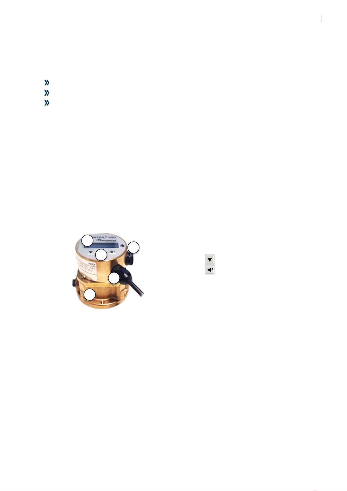
3.2 Device components ............................................................................................................................................... 5
3.3 Power supply ............................................................................................................................................................ 5
3.4 Interfaces.................................................................................................................................................................... 5
4Mounting ......................................................................................................................6
5Installation....................................................................................................................6
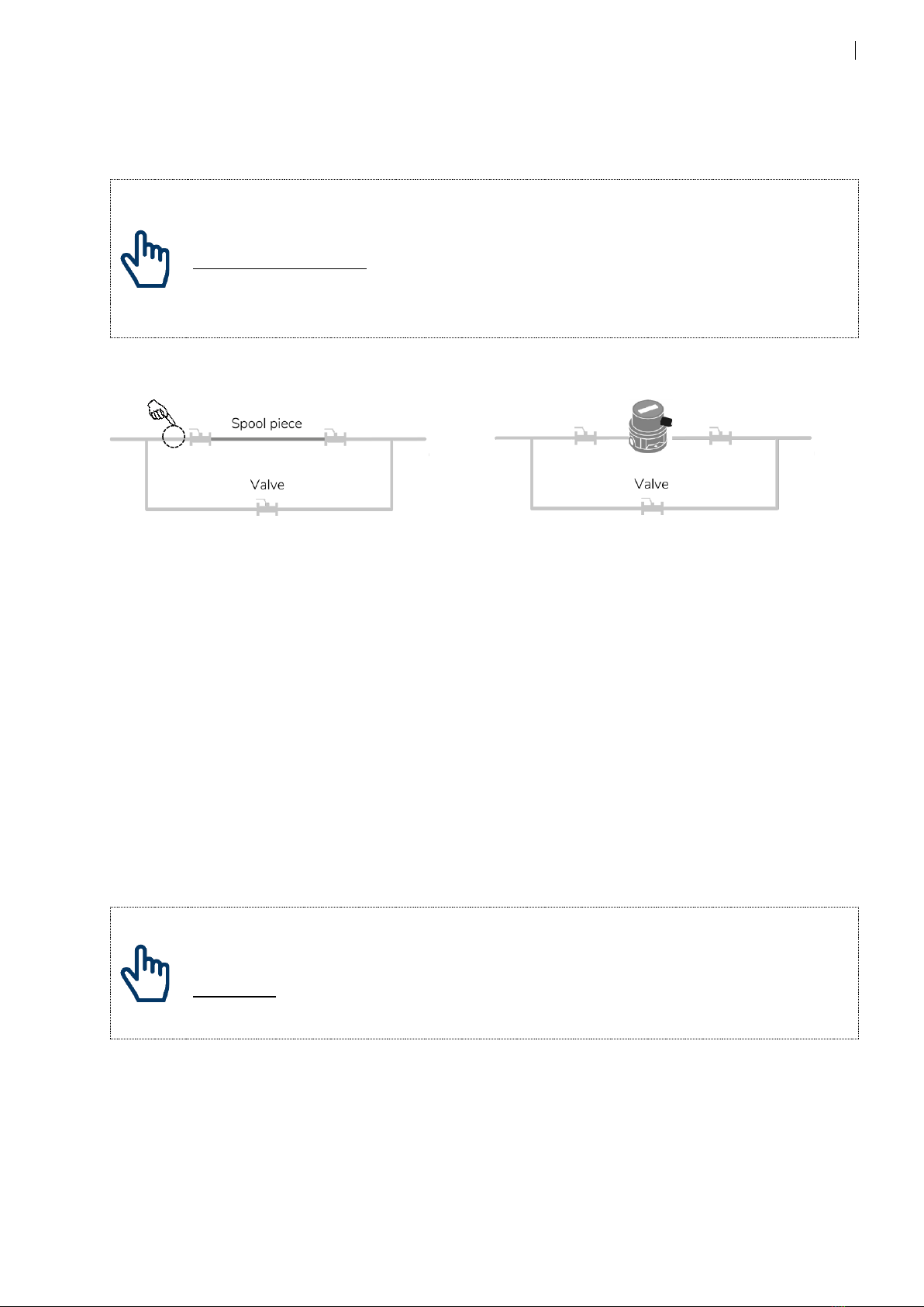
5.1 Mechanical Installation......................................................................................................................................... 6
5.2 Electrical Installation............................................................................................................................................10
6Commissioning...........................................................................................................10
6.1 Display.......................................................................................................................................................................11
6.2 Operation of flow measuring system............................................................................................................12
6.3 General overview of Menu structure.............................................................................................................13
6.4 Counters and instant values .............................................................................................................................14
6.5 Information, Operating hours and Billing....................................................................................................15
6.6 Loggers, unlock and Logbook .........................................................................................................................16
6.7 Output settings......................................................................................................................................................17
6.8 Internal bus communication.............................................................................................................................19
6.9 Units...........................................................................................................................................................................20
6.10 Configuration and System settings................................................................................................................21
6.11 System information..............................................................................................................................................22
6.12 Factory settings .....................................................................................................................................................22
7Maintenance and Repair ...........................................................................................23
7.1 Calibration ...............................................................................................................................................................23
7.2 Service maintenance............................................................................................................................................23
7.3 Spare parts ..............................................................................................................................................................23
8Troubleshooting and error messages......................................................................24
8.1 Troubleshooting....................................................................................................................................................24
8.2 Alarm messages ....................................................................................................................................................25
8.3 Error messages.......................................................................................................................................................25
9Decommissioning, Dismantling and Disposal ........................................................26
9.1 Decommissioning.................................................................................................................................................26
9.2 Dismantling.............................................................................................................................................................26

2
9.3 Disposal....................................................................................................................................................................26
10 Technical Data............................................................................................................ 27
10.1 Model code.............................................................................................................................................................27
10.2 Hardware characteristics....................................................................................................................................27
10.3 Electronic characteristics....................................................................................................................................28
10.4 Output and communication types.................................................................................................................29
11 Appendix ....................................................................................................................32
11.1 Dimensional drawings ........................................................................................................................................32
11.2 Modbus addressing.............................................................................................................................................33
11.3 M-Bus addressing.................................................................................................................................................34
11.4 Settings list..............................................................................................................................................................35
12 Certificates..................................................................................................................37
12.1 EU Type examination certificate MI005........................................................................................................37

3
1Safety
1.1 Intended Use
The device CONTOIL®VZD2 is designed and solely intended for the flow and consumption meas-
urement of Diesel oil and Lubrication oil.
Improper or non-intended use of the device may compromise operational reliability of the device.
The manufacturer accepts no liability for any resulting personal injury or material damage.
1.2 Notes on safety rules and symbols
The devices are designed to meet the latest safety requirements. They were tested and delivered
in a condition that ensures safe operation. Improper or non-intended use of the devices can,
however, be dangerous. Therefore, pay particular attention to the safety instructions within this
manual, which are always shown by the following symbols:
WARNING
WARNING indicates a hazardous situation which, if not avoided, could result in
death or serious injury.
CAUTION
CAUTION indicates a hazardous situation which, if not avoided, could result in
minor or moderate injury.
NOTICE
NOTICE indicates a hazardous situation which, if not avoided, could result in
property damage.
NOTE
NOTE indicates helpful tips and recommendations, as well as information for
efficient and trouble-free operation.
See technical brochure or
mounting and operating manual
Download via QR code or click, on our website

4
1.3 Safety rules and precautions
The manufacturer accepts no responsibility if the following safety rules and precautions are
disregarded:
Any modifications of the device implemented without the prior written consent of the
manufacturer will result in the immediate termination of product liability and warranty.
Installation, operation, maintenance and decommissioning of this device must be carried out
by trained, qualified specialists, authorized by the manufacturer, operator or owner of the
facility. The specialist must have read and understood this entire installation and operating
manual and must follow the instructions contained herein.
Check the supply voltage and the information on the type plate before installing the device.
Check all connections, settings and technical specifications of any peripheral devices.
Do not open the housing or parts of the housing containing electric or electronic components
before the electric power is turned off.
Do not touch any electronic components (ESD sensitivity).
Never exceed the specified classifications for mechanical and electrical load (e.g. pressure,
temperature, ingress protection (IP), voltage etc.).
Release the pressure in the pipe system and reduce the temperature of the medium to a safe
level for humans when carrying out any work involving the system’s mechanical components.
None of the information contained in this manual or in any other documents shall release
planners, engineers, installers and operators from their own careful and comprehensive
assessment of the respective system configuration in terms of functional capability and
operational safety.
The local labor and safety laws and regulations must be adhered to.
1.4 About the operating manual
The manufacturer reserves the right to make changes to technical data without prior notice. The
latest information and versions of this operating manual can be requested from your local dealer
or can be found on our website: https://www.aquametro-oil-marine.com
For smart devices scan QR code on previous page.
WARNING
The manufacturer assumes no liability if the instructions and procedures described
in this manual are not followed!
NOTICE
This installation manual is intended for qualified personnel and therefore does not
include basic working steps. Before operating the equipment or system, this
installation and operating manual must be completely read and understood.
Please retain this manual for future reference!

5
2Scope of delivery and accessories
The scope of delivery is described on the delivery note. Please check all components and parts
delivered promptly after receipt of goods. Transport damage shall be reported immediately on
receipt of the goods.
1 CONTOIL®VZD2 flow measuring system
2 Quick instructions - full Operating instructions as download (this document)
3 mounting kit VSR-set ⅛” - M14x1,5 (only for size DN4)
3Product description
Thank you for purchasing this high-quality flow measuring system.
3.1 Application
The CONTOIL®VZD2 is designed for fuel and consumption measurement applications within the
automotive, industrial, residential, and marine area. It can be used as a single (direct measure-
ment) unit.
3.2 Device components
CONTOIL®VZD2 contains of a longtime proven hydraulic and electronic part with state-of-the-art
sensor technology.
1. Display1)
2. Operating elements1)
Scroll button
Enter button
3. Pressure compensating element1)
4. Connection cable
5. Measuring chamber
1) VZD2 only, not available for VZP2 model
3.3 Power supply
Use the preconfigured cable and connect to a power source of 12 - 24vdc.
The connection to an uninterruptable power supply is recommended.
3.4 Interfaces
The CONTOIL®VZD2 has an isolated RS485 serial connection with either Modbus RTU or
M-Bus and a solid state relay for pulse output.
Cable details are described in section 5.2 on page 10
For details on communication types see technical data, section 10.4 on page 29
3
1
2
5
4

6
4Mounting
CAUTION
Material damage caused by neglected ambient/environment conditions
Danger of malfunction or damage!
•Assuring accessibility for installation, operation, and maintenance
•Mount to rigid object to avoid excessive vibrations
•Use provided mounting holes
1. Use provided mounting holes
5Installation
5.1 Mechanical Installation
Identify the flow measuring system and ensure that the flow measuring system is suitable for the
intended process and conditions. Easy access for reading the flow measuring system and control-
ling the ancillary equipment is important. Provided that the arrow on the housing is in the direc-
tion of flow, the flow measuring system can be installed in any position without any special modi-
fications.
NOTE
Exception
•Do not install upside down
NOTE
Magnetic fields
•Keep away from magnetic disturbances
✓

7
WARNING
Risk of severe injury!
Risk of substantial property damage!
Leakage or rupture due to connections being made using force.
•Never attempt to overcome misalignments (lateral, angular, longitudinal, tor-
sional) using force
•Make sure the piping are flexible enough, if not: use compensators.
•Consider the effects of thermal contraction and expansion.
NOTE
Inclusions of air, foam or gas
•Check piping layout
•Avoid installation in the highest point of the piping system
•Ensure that the measuring system is always filled with liquid
•Installation of by-pass recommended
Make sure that no hazardous fumes can build up in the piping and in the flow measuring system
during commissioning, decommissioning and dismantling. The flow measuring system must at all
times during operation be completely filled with liquid. Check the flow measuring system periodi-
cally for tightness of the connections and for proper functioning. If work is to be done on the in-
stallation, before each intervention: release the pressure in the installation if hazardous liquids are
used, wear protective clothing and safety goggles, place a collecting tray underneath the installa-
tion.
Preparing for installation
Check flow measuring system and installation material.
Compare the data of the flow measuring system name plate with the expected maximum condi-
tions of the installation. They may not exceed the flow measuring system specifications:
•Maximum flow rate (Qmax l/h) (preferred max. Qcont)
•Maximum operating pressure (PN bar)
•Maximum temperature (°C)
•Appropriate connections and seals (gaskets)
•Fasteners for the flow measuring system
•Material and temperature resistance of measuring system to measured liquid
Correct layout of flow measuring system and accessories
If the flow measuring system is used for viscosities higher than 5 mPa.s, or if it is mounted on the
suction side of a pump, the pressure loss and the flow rate that can still be attained should be de-
termined with the help of the pressure loss curves provided in CONTOIL®Technical Information.
In addition, the pressure loss due to installed filters must be taken into consideration.

8
NOTE
Select the flow measuring system and ancillaries according to the working conditions
listed below:
•Flow rate (maximum expected application flow rate = maximum continuous
flow rate of flow measuring system (Qcont). Qcont shall not be exceeded
•Material compatibility with medium
•Operating pressure and temperature
•Ambient temperature
•The flow measuring system must be selected according to the max. application
flow rate and not according to the pipe diameter. If necessary, adapt the pipe-
work.
•Use Non-Return-Valves after the flow measuring system if return flow can
occur.
NOTICE
Pulsations / dirt
Damage or malfunction of flow measuring system
•Avoid flow pulsations
•Install pulsation reducer
•Avoid dirt particles/welding pearls
•Install sufficient fine filter
CAUTION
Risk of injury!
Unauthorized start-up while mounting.
•Make sure that unauthorized start-up is not possible while mounting.
•Comply with the applicable working regulations during all work on the system.
NOTE
Altering an existing system
•Take the flow measuring system out of operation in order to flush the system
clean of debris.
•Flushing information on page 9.

9
Flushing of pipes
If the pipes are to be flushed at a later stage, stop valves shall be provided on both sides of the
flow measuring system.
NOTICE
Damage or malfunction of flow measuring system
Accumulation of debris
•replace the flow measuring system with a spool piece
•ensure of no dirt accumulation in front of the valve
Flushing Measuring
Trial operation
Start trial operation (without flow measuring system); open the stop valves slowly when doing
this.
•Carry out a pressure test prior to measuring system installation
•Check for leaks and tightness of all bolts
•Flush the pipework until clean (flow measuring system out of pipeline)
•Release the pressure and stop the system again
This trial operation ensures that all pipework is tight, clean and free of foreign matter that could
damage the flow measuring system.
Installing the measuring system in the pipe
Remove the protection plugs or caps from the flow measuring system (inlet and outlet).
Insert the flow measuring system into the pipeline in the prescribed position and flow direction.
The arrow on the flow measuring system should correspond with the direction of flow. Install
mating flanges parallel and without tension in the pipe.
NOTICE
Risk of leakage
Fuel sprays
•Always use appropriate sealing materials as per connection type.
Flow measuring system

10
5.2 Electrical Installation
NOTICE
Risk of malfunction or damage
Injuries due to electrical power or systems
•Ensure that the system is safe to work
•Follow local safety guidelines
•Review of technical data, chapter 8.1
5.2.1 Cabel configuration
1. White supply +
2. Brown supply -
3. Green relay output
4. Yellow relay output
5. Pink RS485 A
6. Grey RS485 B
NOTE
Power supply
•Supply voltage: VDC 12 –24; check polarity
•Use uninterruptable power supply for CE-MID applications.
6Commissioning
NOTE
Modification of settings
•Modification of operation settings may result in faulty or wrong measuring
results.
•Always consult and read this manual when adjusting operation settings.
Multiple output functions are available.
One potential-free relay output:
•Pulses; for external totalizer or monitoring systems.
•Frequency signal; for flow rate displays
•Limiting switch; Switching function with programmable high and low flow rate (NO / NC).
•Status switch; control functions for Errors, Alarms and Supply Voltage (NO / NC).
One isolated RS485 serial connection:
•Modbus RTU or M-Bus

11
Startup and commissioning of mechanical part of flow measuring system:
Open valves slowly, fill pipework gradually. Vent the installation well.
NOTICE
Damage or malfunction of flow measuring system
Pressure surges, inclusion of air
•avoid pressure surges, open valves slowly
•air causes measuring errors, ensure that no air is in the system during operation
Check the tightness of the connections and watch for leakages.
Function check with electronic display: read the instantaneous flow value.
Should the established flow rate be greater than the specification of the flow measuring system
(Qcont),
either a flow control valve (throttle) must be inserted behind the flow sensor or a larger size flow
measuring system must be used.
6.1 Display
1. Menu Identification info (level 2 and 3)
2. Status indication symbols
3. Main display
4. Units
Symbols of status display
Calendar icon
Visible at log data display
Arrow up / down
Limit switch min/max
Event in / event out
Flow bars
Indicates flow recognized
Editing locked / unlocked
Indicates lock status
Pencil
Indicates editing mode
Caution and red flashing
Indicates alarm
Caution and red on
Indicates error
4
1
2
3

12
6.2 Operation of flow measuring system
1. Scroll button
2. Enter button
Use Scroll button to scroll the menu and to change field values.
Use Enter button to enter submenus and to edit / confirm field entries.
Backwards scroll: press and hold the Enter button, use Scroll button to scroll backwards.
Return to “home” screen (totalizer volume): press and hold the Scroll button, press Enter
button once.
The menu can be viewed without any code.
If parameters need to be changed the device must be unlocked ( ) with the user code.
Scroll to the menu item “unLoc” press enter to select and enter to edit, the pencil ( ) is dis-
played and the first left digit will start flashing, which means, the unit is ready for the entry of the
first digit of the user code 00001111. Press the Enter button to accept the value (in our case 0)
and to move to the second digit. Continue this way to enter all code numbers.
At the end of the procedure a will be displayed. The flow measuring system is now unlocked
and in edit mode. Parameters can be changed.
If no button is pressed within 15 minutes, the device returns to the “home” display and returns to
locked mode. Any entries that have not been completed by pressing the Enter button are re-
jected.
In order to guarantee accurate measurement, the electronic module of the flow measuring system
requires adjustment. During factory calibration, the data for nominal size and the exact correction
factor value of the measuring chamber volume are entered for this purpose.
These parameters cannot usually be changed again.
Reset of sub totalizers [trIP-Cnt]
To reset all sub totalizers, go to “trIP-Cnt”, scroll to “rE”and press enter.
All sub totalizers are reset.
Compensation to Norm-Volume and Mass flow calculation: (Config/CM)
Compensation to norm-volume and Mass flow can be turned on, display and output parameters
are added accordingly.
This means that the volumetric expansion of the medium is calculated using actual temperature
and normalized to the actual volume at 15°C (volume at base condition) this value is also used to
calculate mass / mass flow. Compensation calculation is according to DIN51757.
1
2

13
NOTE
Visibility of counters and modification of settings
•Counters and settings related to compensation and mass calculation, are only
visible or functional if compensation under menu “ConFIG/CM” is turned on to
either “SGL OIL” or “dbL OIL” compensation
NOTE
Counter values for CE-MID (2014/32/EU)
•Only the volume counter values are valid for CE-MID compliant measurements.
6.3 General overview of Menu structure
Menu level 1
Menu level 2
Menu level 3
description
el
CountEr
Counter values (totalizers)
trIP-Cnt
Trip counter (subtotals)
InStAnt
Instant values
InFo
only visible if an alarm or error is active
OP_hourS
Operating hour information
bILLInG
option -xx-xC
only visible with option MID005
LoGGEr
Log values
unLoc
Code, to unlock and edit values
LoG
only visible with user code
P-Out
Digital pulse outputs (counting signal)
F-Out
Digital frequency outputs (flow signal)
S-Out
Status outputs (limits & alarms)
Int-BUS
Internal bus communication in single mode
UnItS
Units
ConFIG
System configuration
SYS-SEt
System settings
SYSINFO
System Information
DisplayTest
displays all characters on the display
Some menu items only visible based on preset conditions (e.g., compensation on/off)
Only visible if option CE-MID005 is set / ordered
Access / edit level
el
none
0
user
1
user (without option “C” MID)
2
Supervisor / manager
3
Service technician
4
production
5
no edit, read only

14
6.4 Counters and instant values
Menu level 1
Menu level 2
Menu level 3
description
el
CountEr
Counter values (totalizers)
SUPPLY
counter values of single or SL counter
0
V
measured raw volume
4
dV
distillate fuel volume corrected
4
hV
heavy fuel volume corrected
4
dM
distillate fuel mass calculated
4
hM
heavy fuel mass calculated
4
dC
Co2 distillate fuel
4
hC
Co2 heavy fuel
4
trIP-Cnt
Trip counter (subtotals)
SUPPLY
trip values of single or SL counter
0
rE
reset trip counter
1
V
raw volume
dV
distillate fuel volume corrected
hV
heavy fuel volume corrected
dM
distillate fuel mass calculated
hM
heavy fuel mass calculated
dC
Co2 distillate fuel
hC
Co2 heavy fuel
InStAnt
Instant values
SUPPLY
instant values of single or SL counter
0
Qv
raw volume flow
Qc
standardized volume flow (norm volume)
Qm
calculated mass flow
dE
calculated density
t
fuel temperature

15
6.5 Information, Operating hours and Billing
Menu level 1
Menu level 2
Menu level 3
description
el
InFo
only visible if an alarm or error is active
A-tEMP
temperature alarm
A-Flow
flow alarm
A-SIM-P
alarm when P-Out simulation is on
A-SIM-F
alarm when F-Out simulation is on
A-o1 LI
output settings need to be adjusted, out of limits
A-Man
alarm when device is being manipulated (external)
A-SIM-S
alarm when system simulation is on
E-SYS
system error (call for service)
E-LOG
Log backup is faulty (call for service)
E-tEMP
temperature error, Hardware faulty (call for service)
E-Flow
flow error, Hardware faulty (call for service)
E-EEP
EEPROM error (call for service)
OP_hourS
Operating hour information
H0
operating hours
5
H1
hours in preferred range (Qmin –Qcont)
5
H2
hour in upper flow range (Qcont –Qmax)
5
H3
hours above max. flow (Qmax)
5
HA
time in alarm mode (h)
4
HE
time in error mode (h)
4
bILLInG
option -xx-xC
only visible with option CE-MID005
Nr
select billing cicle nr
0
Sd
set date (dd.mm.yy)
1
Ed
execute date (dd.mm.yy)
V
measured raw volume
dV
distillate fuel volume corrected
hV
heavy fuel volume corrected
dM
distillate fuel mass calculated
hM
heavy fuel mass calculated
dC
Co2 distillate fuel
hC
Co2 heavy fuel
HA
time in alarm mode (h)
HE
time in error mode (h)

16
6.6 Loggers, unlock and Logbook
Menu level 1
Menu level 2
Menu level 3
description
el
LoGGEr
Log values
LG
select log
0
Month
log data of every end of the month
0
dAY
log data of every end of the day
0
noon2n
log data of every noon
0
Hour
log data of every end of the hour
0
MInutE
log data of every end of the minute
0
Nr
select numbers back from now (1, 1-60)
0
dA
date of log entry (dd.mm.yy)
ti
time of log entry (hh:mm)
V
measured raw volume
dV
distillate fuel volume corrected
hV
heavy fuel volume corrected
dM
distillate fuel mass calculated
hM
heavy fuel mass calculated
dC
distillate fuel Co2
hC
heavy fuel Co2
HA
time in alarm mode (h)
HE
time in error mode (h)
qv
max volume flow
qm
max mass flow
t
max temperature
unLoc
Code, to unlock and edit values
Lo
user or manager code
0
LoG
only visible with user code
Nr
select numbers back from now (1, 1-100)
1
dA
date of log entry (dd.mm.yy)
ti
time of log entry (hh:mm)
A-tEMP
temperature alarm
A-Flow
flow alarm
A-SIM-P
alarm when p-out simulation is on
A-SIM-F
alarm when f-out simulation is on
A-o1 LI
output settings need to be adjusted, out of limits
A-Man
alarm when device is being manipulated (external)
A-SIM-S
alarm when system simulation is on
E-SYS
system error (call for service)
E-LOG
Log backup is faulty (call for service)
E-tEMP
temperature error, Hardware faulty (call for service)
E-Flow
flow error, Hardware faulty (call for service)
E-EEP
EEPROM error (call for service)
I-PWr UP
last power up

17
6.7 Output settings
Menu level 1
Menu level 2
Menu level 3
description
el
P-Out
Digital pulse outputs (counting signal)
Fc
select function
1
IMPULS
digital output pulses
1
SG
select output signal
1
VoLuME
raw volume
1
VoL dVC
volume compensated distillate fuel
1
VoL hVC
volume compensated heavy fuel
1
MASS dVC
mass calculated distillate fuel
1
MASS hVC
mass calculated heavy fuel
1
CO2 dVC
CO2 volume compensated distillate fuel
1
CO2 hVC
CO2 volume compensated heavy fuel
1
UP
pulse value (0.01, 0.001-1000)
1
MS
pulse width (20, 2-500)
1
SI
simulation of output
1
#.###
value to be simulated
1
oFF
simulation off / on
1
oFF
outputs off
1
Ac
active logic function (NO/NC)
1
St
status of function on/off
1
F-Out
Digital frequency outputs (flow signal)
Fc
select function
1
oFF
outputs off
1
0-200Hz
frequency output signal
1
SG
select output signal
1
FLOW
frequency of flow Q
1
FLOW C
frequency of compensated flow Qvc
1
MASSFLO
frequency of mass flow Qm
1
tEMP
frequency of temperature tMP
1
dEnSitY
frequency of density dEn
1
SL
signal value low (0; 0-Qmax)
1
SH
signal value hi (Qmax; 0-Qmax)
1
FL
frequency low (0Hz; 0-200Hz)
1
FH
frequency hi (200Hz; 0-200Hz)
1
SI
simulation of output
1
#.###
value to be simulated
1
oFF
simulation off / on
1
Er
action on error
1
cont
continuous signal on error
1
HI
hi frequency signal on error (200Hz)
1
Lo
lo frequency signal on error (0Hz)
1
St
actual output frequency
1

18
Menu level 1
Menu level 2
Menu level 3
description
el
S-Out
Status outputs (Limits & alarms)
Fc
select function
1
LIMIT 1
1 point limit switch
1
SG
select signal the limit applies
1
FLOW
limit on flow Q
1
FLOW C
limit on compensated flow Qvc
1
MASSFLO
limit on mass flow Qm
1
tEMP
limit on temperature tMP
1
dEnSitY
limit on density dEn
1
L1 ,+
limit value; (Qcont, 0 to full range of size)
1
HY (+/-%)
hysteresis of value (5, 0.0-99.9 %)
1
Ac
active logic function (NO/NC)
1
St
status of function on/off
1
LIMIT 2
2 point limit switch (min/max)
1
SG
select signal the limit applies
1
FLOW
limit on flow Q
1
FLOW C
limit on compensated flow Qvc
1
MASSFLO
limit on mass flow Qm
1
tEMP
limit on temperature tMP
1
dEnSitY
limit on density dEn
1
L1 ,
limit value min. (Qmin, 0 to full range of size)
1
L2 +
limit value max. (Qcont, 0 to full range of size)
1
HY (+/-%)
hysteresis of value min. / max. (5, 0.0-99.9 %)
1
Ac
active logic function (NO/NC)
1
St
status of function on/off
1
StAtE
action on alarm or error status
1
Ac
active logic function (NO/NC)
1
St
status of function on/off
1
oFF
outputs off
1
Ac
active logic function (NO/NC)
1
St
status of function on/off
1

19
6.8 Internal bus communication
Menu level 1
Menu level 2
Menu level 3
description
el
Int-BUS
Internal bus communication in single mode
Fc
select function
1
ModbuS
Modbus RS485
1
Ad
Address (1, 1-247)
1
BA
Baud rate
1
300
1
2400
1
9600
1
19200
1
38400
1
PA
Parity
1
odd
1
NONE
1
EVEN
1
M-BUS
M-Bus RS485
1
Ad
Address (0, 0-250)
1
SE
Secondary address
1
BA
Baude rate
1
300
1
2400
1
9600
1
Ac
Access counter
1
AP
Application Reset
1
CANCEL
1
rESEt
1

20
6.9 Units
Menu level 1
Menu level 2
Menu level 3
description
el
UnItS
Units
V
units for volume
2
L
liter
2
GAL
us gallon
2
m3
cubic meter
2
Vd
decimals for volume value
2
0.001
2
0.01
2
0.1
2
1
2
M
units for mass
2
Kg
kilogram
2
T
ton
2
lbs
pound
2
Md
decimals for mass value
2
0.001
2
0.01
2
0.1
2
1
2
Qv
units for volume flow
1
L/s
liter per second
1
L/m
liter per minute
1
L/h
liter per hour
1
m3/h
cubic meter per hour
1
GA/h
gallon per hour
1
Qm
units for mass flow
1
Kg/h
kilogram per hour
1
t/h
ton per hour
1
LB/h
pound per hour
1
dE
Kg/m3
unit for density
1
t
units for temperature
1
°C
degrees Celsius
1
°F
degree Fahrenheit
1
VP
units for volume pulse
1
mL
milli liter
1
L
liter
1
m3
cubic meter
1
GAL
us gallons
1
MP
units for mass pulse
1
Kg
kilogram
1
t
ton
1
lbs
pound
1
This manual suits for next models
1
Table of contents
Other Aquametro Measuring Instrument manuals

Aquametro
Aquametro CALEC ST Service manual

Aquametro
Aquametro AMTRON E-30 Service manual

Aquametro
Aquametro AMTRON X-50 Service manual

Aquametro
Aquametro AMTRON SONIC D Service manual

Aquametro
Aquametro AMBUS IS User manual

Aquametro
Aquametro CONTOIL VZF II Service manual

Aquametro
Aquametro CONTOIL DFM Service manual

Aquametro
Aquametro CONTOIL Series Guide

Aquametro
Aquametro CONTOIL VZO 4 Service manual