Aquapeutics Caribbean User manual

0
CARIBBEAN
INSTALLATION MANUAL

1
Thank you for choosing the Aquapeutics Caribbean computerized steam shower /
whirlpool bath. Please read the following manual in its entirety before assembling your
unit. It is also very important to follow the safety suggestions outlined below at every
use.
1. Please keep in mind that like most shiny bathroom surfaces when they get
wet they may become slippery. Take care not to slip or fall.
2. Children should only use this product under adult supervision.
3. Users who suffer from heart disease or have high blood presser should
exercise greater care when using this product.
4. Senior citizens, pregnant women and those who are of ill health are
advised to get a doctors opinion on the recommended frequency of use of
this product.

2
1. Technical parameters & package information
1.2 Package information
1. Upon the arrival of your Aquapeutics spa take care to make a thorough inspection for any visible damage to the
shipping container. Visible damage should be reported to your carrier immediately. All SHIPPING DAMAGE should
be noted on the assigned shipping document.
2. It is recommended that all rough plumbing and electrical work be completed before the assembly of your
Caribbean begins.
3. At least two people are required to lift the larger pieces into position during installation.
4. Tools:
Wooden mallet open end wrench level Tape measure Screwdriver Pencil 4mm Hex wrench
Electrical data
Dimensions (inches)
N.W
capacity
Circuits
Power
frequency
Length
Width
Height
1@ 110V 11.8 amps
1 @ 220V 13.6
amps
1300W
and
3000W
50~60Hz
63.8
63.8
87
390 lbs
40 Gal
Please note: If you have
purchased a Tub with the
additional heater option it
is very important to
understand that the
electrical requirements for
your unit have changed.
The heater requires a
second separate electrical
circuit that can supply 13
amps at 110 volts with GFI
in addition to what your
tub had originally needed.
Installation instructions for
your optional heater are in
the installation section of
this manual.

3
Drain pipe can be offset as much as 6 inches from tub drain.
2.2 Installation drawing for waste plug:
Installation instructions Rough Plumbing & Electrical

4
MODEL: Caribbean Installation instructions:
A、Water supply: Hot and cold water supply lines are half inch NPT pipe thread
Power supply:A220Volt,13 amp service with GFI is necessary to energize the steam room-spa and a
110 volt 11.8 amp circuit with GFI is needed for the whirlpool bath. Please note: If you have purchased a
Tub with the additional heater option it is very important to understand that the electrical requirements
for your unit have changed. The heater requires a second separate electrical circuit that can supply 13
amps at 110 volts with GFI in addition to what your tub had originally needed.
B、The size of breakers and wire gages needed is determined by local, state and national codes as
interpreted by the installing electrician. The length of the wire going to the steam generator from the
wall should be 5 feet, while the length of the telephone line needed is 7 feet. This allows the unit to be
pulled out from the side walls if maintenance is ever needed.
C、Drainage: The diameter of the drain pipe needs to be at least 2 inches. The position of the drain hole
can be within 6 inches from the hole shown in the drawing on the previous page. It is also very
important that the drain line not have a trap. It must be a straight drain line, as the shower-spa has its
own built in trap for your convenience.
Notes:
(1) The distance from the top of the steam room to the ceiling of the area where it is installed should be
4 inches or greater. (The room should be at least 4 inches taller than the spa.)
(2) It is recommended that the water pressure be at least 43 PSI and both the cold and hot water pressure
should be as equal as possible. If the pressure is lower than required, have your plumber install the
necessary equipment to increase the water supply pressure.
(3) Please have ground fault interrupter (GFI) protection on all power supply lines to the spa.
(4) It is easier to line up all panels with the hardware loose. During initial assembly please attach all
fasteners loosely, then when the unit is completely erected, snug up all bolts and screws.

5
1c
1b
1a
Chrome spacer
3. Installation Steps
1. Place the shower floor unit (as pictured below 1a)
16-24 inches from its final installed location. Now adjust
the leveling feet (1c) to bring the unit flat and level by
using a 3 foot level (1b) and an open end or adjustable
wrench to turn the adjusting nuts. This will raise or lower
each corner as needed. Once the unit is level and flat lock
each leg into position with its locking nut.
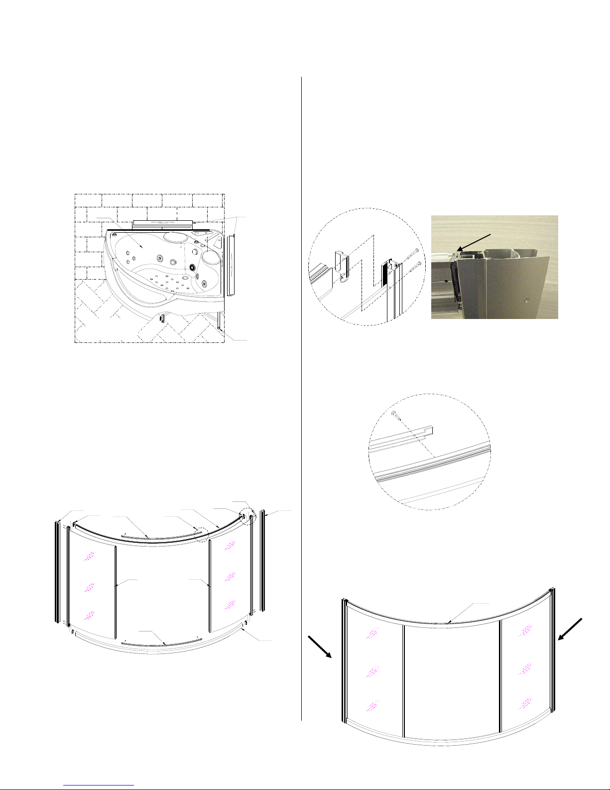
2. The fixed glass wall (minus the sliding glass
door) must be assembled first before it is installed
to the tub. Take care when inserting the glass
components into the aluminum channels. The
Fixed glass component installation diagram (Figure
2) is below. Please insert the rubber gaskets
between the glass and aluminum channels where
indicated.
The glass walls are framed by the curved rails on
the top and bottom and with the aluminum
extrusions to the left and right.
①Connect the left and right fixed glass walls (2c)
to the upper and lower aluminum curved rails
(2d) by using 8 pieces 3/16 x 1 ¼ inch (2a)
screws with the plastic chrome spacer in
between the curved rails and the vertical side
channel. As shown in figure 2.1
②Use 4 pieces 3/16X ¾” screws (2e) to connect
the roller track cover (2f) with the upper and
lower inside rails. (Figure2.2)
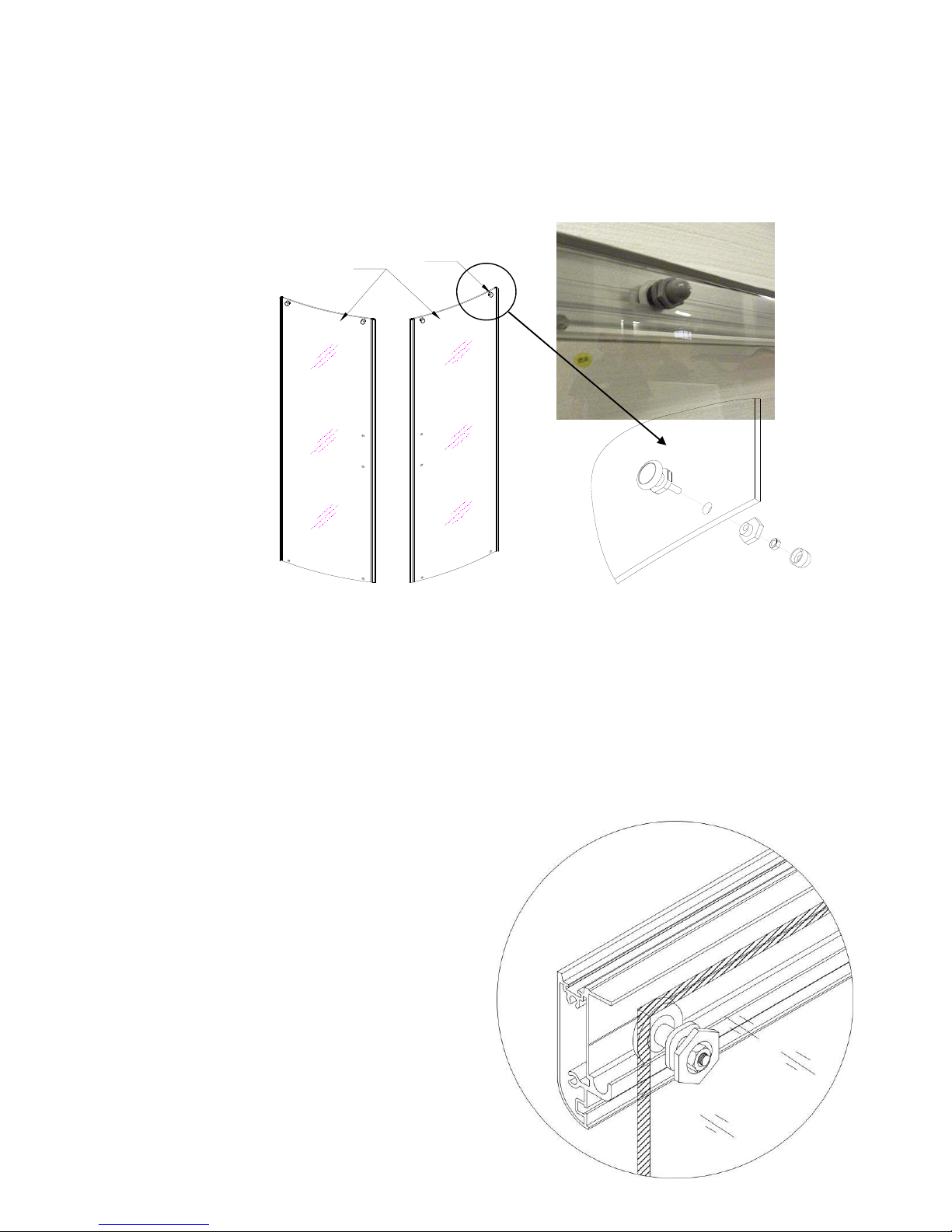
③According to the arrow tips direction, insert the
left and right side corner aluminum extrutions
(2g) into the fixed glasses to complete the
curved fixed glass wall (Figure 3).
2f 2e 2d 2b 2g
2d
2c 2c
2f
2g 2b
2a
Figure2
Figure1
Figure2.1
Figure 2.2
2h
Figure 3

3e
3. Steam room installation diagram, as follows (Figure 4)
①Using ¼ x 1 inch bolts (3a) connect the left and right small panels(3b,3c) to the middle panel(3d)
respectively to complete the whole back panel of your steam shower (3e).(Figure 4.1)
Figure 4.1
Figure 4

Carefully lift (two people are recommended) the back panel onto the bathtub (3f), fasten them together
using1/4x 1 inch bolts. (Figure4.2)
Then carefully lift (two people are recommended) the Glass wall and door assembly (3g) onto the
bathtub, attach the glass door to the back board by using3/16x 3/4 inch bolts.(Figure 4.3)
4. Final installation steps:
Figure4.2
Figure 4.3
Figure 5
Place the ceiling /roof of the spa
(3i) onto the unit, then using 1/4x
1 inch bolts, bolt it to the back
panel, and use 3/16x 3/4 inch
screws to fasten the roof to the
glass wall/ door. (Figure 5)

Eccentric roller detail: The eccentric assemblies (figure 6.1, the picture above and the drawing below) are used in both
the upper and lower tracks of the sliding doors. The top ones are installed first. To install the eccentric you first
remove the chrome plastic decorative cover). Unthread the nut, remove the washer, insert the grey plastic eccentric
through the glass door and then replace the washer, and snug up the nut. By turning the grey eccentric wheel the white
wheel is raised or lowered. This allows you to adjust the ride height of each side of the sliding glass door. You want
the door to be as plumb as possible. After the correct positions for the top eccentrics have been determined then you can
tighten them as needed. Now the bottom eccentrics may be installed using a similar method only no fine tuning is
necessary. The bottom ones are simply inserted first their lowest position and then twisted 180 degrees to their highest
position to lock them into the track.
C
①Install the upper rollers (4b) to the sliding glass door (Don’t install the lower rollers first), Then hang
it onto the curved upper rail. After that, place the lower rollers in their track push the threaded portion of
the bolt through the hole in the glass door and install as shown in figures 6 and 6.1
4b
4a
Figure 6
Figure 6.1
Outside of spa
Inside of
spa

②Assemble the handles (4c) to the sliding glass doors (Figure 7). Test the doors to see that they can be
opened and closed smoothly and quietly. (Figure 8) If not then readjust the rollers as explained in the
previous step.
(Figure 9) Connect all hoses to and from the Steam generator. The appropriate outlets/ inlets are labeled in the
above diagram and are visible in the photo below. The Steam generator drain hose is pushed onto the fitting (straight
or elbow) connected to the Steam Generator. It is secured to this fitting by a clamp and a 3/16 X 5/8 inch round head
fastener as is shown in the above figure. It is also shown assembled in the photo below.
Outside of spa
Figure 7
4c
Figure 8
Steam outlet
Steam generator
Steam drain
Inside of spa
Electrical feed
Cold water feed
connector

④Connect the insulated black high temperature steam pipe, which is on the steam outlet, to the steam
jet’s connector on the spa’s back panel. (Figure 10)
⑤The water hose for the rainfall shower goes through the hole in the shower roof /ceiling and then connect
it to the elbow fixture of the shower head with a clamp as is shown in the below figures. (Figure 11)
Black insulated high temperature
steam pipe
Front and side view of Steam outlet
Figure 10
Figure 11
Rainfall shower hose
When bending the insulated steam hose, please Use Extreme Care not to crimp the hose as
you feed it through the appropriate hole in the tub section.
The rubber washer (gasket) that is secured by a wire tie is inserted into the end of Steam hose
The all silver hose is the water supply feed hose to the Steam generator. It is attached here
Photo is not of Caribbean. But connections are the same. The placement of
components may be different.

⑥Please refer to the labels (with icons) on the wires of the various low voltage components. They may include
Telephone, CD player/ radio, loudspeaker, LED lights, fan, control panel and the ozonizer O3 shower self cleaner.
Connect the wires sharing the same labels and/or properly mated connector pairs. The radio antenna will need to be
unrolled and placed for best reception. See figure 12.
16. Connect the hot and cold water hoses, the red one is for hot water, while the blue one is for cold. Both the hot
and cold water supply lines are half inch NPT pipe thread.
Figure 12

This wire when
coming from the tub
is 110 volts.
When it comes from
the steam generator
it is 220 volts.
This side is fed and
connected by your
electrician,
110 volts to power
the tub or 220 volts
when energizing
the steam
generator.
If you have purchased the optional tub water heater the following image and instructions are for you. If you
have not then please skip and disregard this section and you may pick up on the next page.
Pick a side wall water jet pipe that is convenient to work on. Measure the distance taken up by the water
heater. (Approximately 7 and 5/8 inches). Cut this part out. Glue the ends of the water heater and wait until
the glue sets as per the manufactures instructions. Plug the heater in. It has its own thermostatically
controlled on/off and temperature controls. It will turn on when there is water present and the temperature
is below 102degrees and will shut off at 104 degrees. Remember that this heater is plugged into a separate
GFI 110 volt circuit as discussed in two other sections of this manual.

While the Caribbean shower Spa is still 16-24 inches away from its final installed position all joints and seams should
be calked with a high grade silicone sealant. Then fully test the unit. Then slide it into its final installed position.
4. Spray and foot massage installation
4.1 Connect the hose of the hand-held shower head (B) by screwing it into nozzle (A) as depicted below
and, then put the hand-held shower head into its cradle. (C)(Figure 14)
Figure13
Figure 14

OFF
ON
30
35
38
45
50
°C
5a
5b 5c
5a1
5a2
5a3
The 5 way selector switch can send temperature
controlled water to the tub, foot massage,
hand-held shower head, the rainfall shower, or the
back message jets.
When the dial (5a1) has the hand-held shower
selected, as noted by the icon, water will come out
of the left shower head.
When control knob (5b) is opened then both
hand-held showers will work.
When the selector dial is in the body massage
position water comes out of the left body massage
jets. When control knob (5c) is opened then both
sets of body massage jets will work.
Knob (5a3) adjusts the temperature of the water
and knob (5a2) is used to adjust the amount or rate
of the water entering the spa.
The five way selector (5a1) may be set to and from
any position even with the water running
4.2 Use the same technique to install the foot massage unit. Its nozzle is located approximately 16 inches below the
right side (as you enter) hand held sprayer nozzle. When using the foot massager open the cover of the unit as depicted
in the illustration below.
Figure 15)

6. Water route connecting diagram
Hand shower
connector
Back jet
connector
Hand shower
connector
Back jet
connector
Head shower
connector
Spout
connector
Foot massage
connector
Hot water in
Cold water in
Steam
connector
From
back
Hand shower
diverter
Back jet
diverter
Body

Attention: Within your warrantee period please do not break the seal on the electrical box
or the steam generator. Doing so will void your warrantee. There are no user serviceable
parts inside. DO NOT repair or replace these units on your own. If you do experience
any problems, please contact Aquapeutics’Toll Free Customer Service line 1 (800)
290-6812 for after-sale service.
Table of contents
Other Aquapeutics Shower Cabin manuals