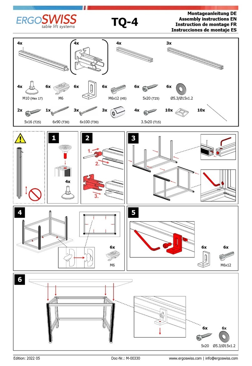
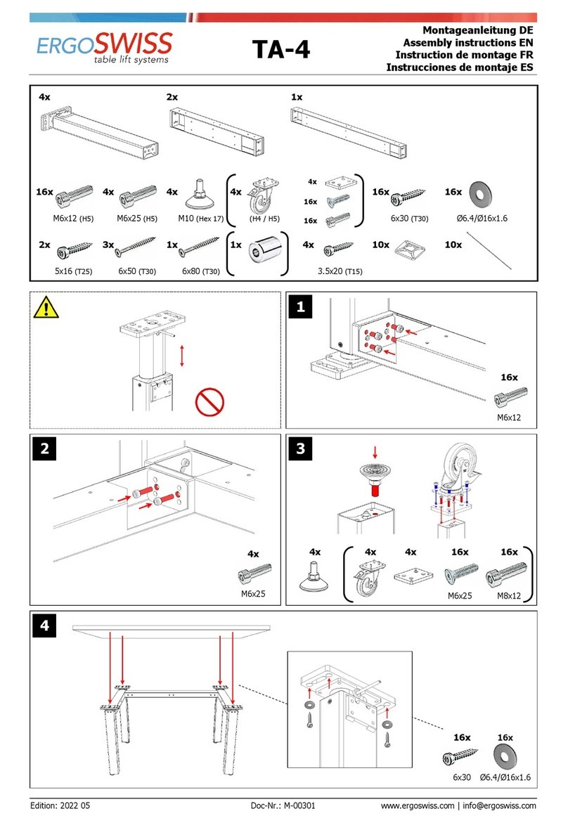
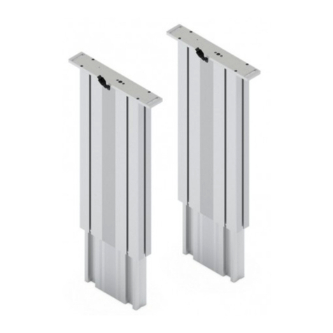
Ergoswiss SL 13 Series User manual

Operating instruction
Spindle lifting system SL/SK/SM 13xx
Document no.: B-00361
Edition 2024 02
Operating instruction EN
Copyright by Ergoswiss AG
Page 1of 29
Operating instruction – Spindle lifting system SL/SK/SM 13xx with SCT iSMPS
It is essential to read this operating instruction thoroughly before commissioning the system.
The manual must be kept in close proximity to the system for future reference.
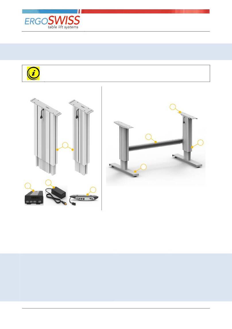
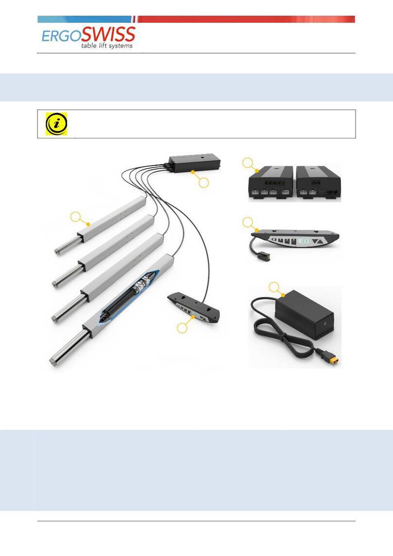
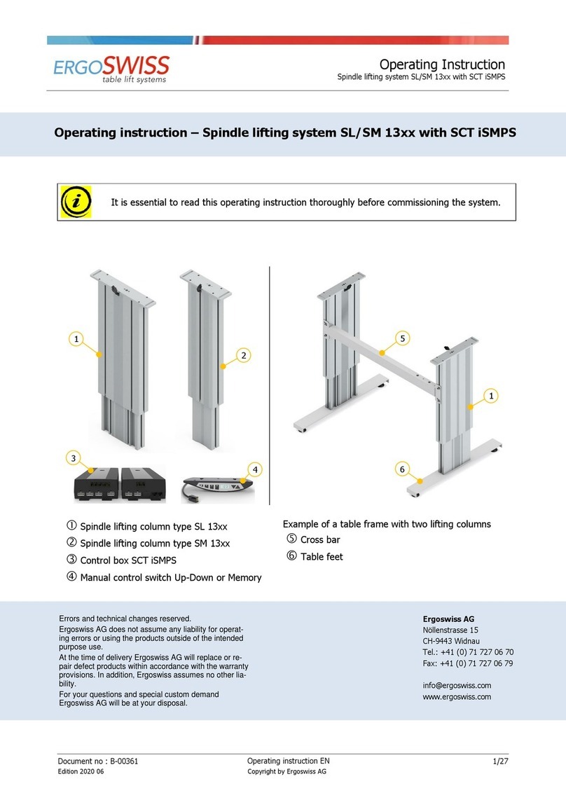
Spindle lifting column of Type SL, SK or SM
Control box SCT iSMPS
Hand switch Memory
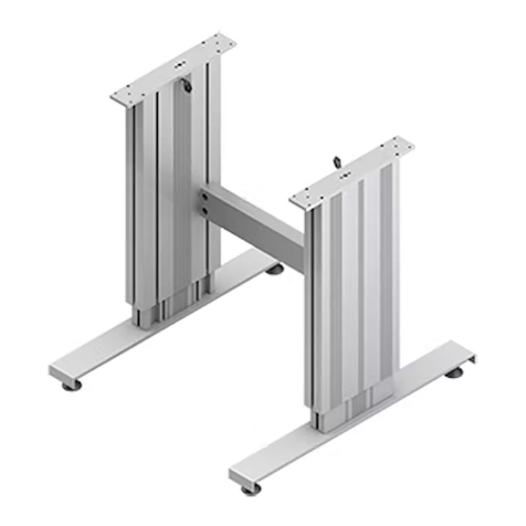
Example of a frame with two lifting columns:
Table plate support
Cross bar
Table feet
Errors and technical changes reserved.
Ergoswiss AG does not assume any liability for operating errors or
using the products outside of the intended purpose use.
At the time of delivery Ergoswiss AG will replace or repair defect
products within accordance with the warranty provisions.
In addition, Ergoswiss assumes no other liability.
For your questions and special custom demand Ergoswiss AG will
be at your disposal.
Ergoswiss AG
Nöllenstrasse 15
CH-9443 Widnau
Tel.: +41 (0) 71 727 06 70
Fax: +41 (0) 71 727 06 79
info@ergoswiss.com
www.ergoswiss.com
5
6
1
1
4
2
3

Operating instruction
Spindle lifting system SL/SK/SM 13xx
Document no.: B-00361
Edition 2024 02
Operating instruction EN
Copyright by Ergoswiss AG
Page 2of 29
This operating instruction applies to:
Lifting system SL 13xx, SK 13xx and SM 13xx with control box SCT iSMPS
Example.: Lifting system SL 2340 EU 12 (Item number: 901.41017)
Example.: Lifting system SM 4340 EU 12 (Item number: 902.41037)
Description
Standard variations
SL
Lifting element type
SL, SK, SM
2340
Number of lifting elements
1, 2, 3, 4
2340
Spindle pitch in mm
3 mm
2340
Stroke length in cm
30 cm, 40 cm
EU
Power cable
EU, CH, US
12
11 = Hand switch Up-Down ; 12 = Memory
12
Frame SL 13xx, SK 13xx and SM 13xx with control box SCT iSMPS
Example.: Frame SL 2340 960-1610 EU 12 (Item number: 901.51017)
Example.: Frame SM 2340 970-1620 EU 12 (Item number: 902.51017)
Description
Standard variations
SL
Lifting element type
SL, SK, SM
2340
Number of lifting elements
1, 2, 4
2340
Spindle pitch in mm
3 mm
2340
Stroke length in cm
30 cm, 40 cm
960-1610
Distance between lifting elements
Telescopic cross bar
EU
Power cable
EU, CH, US
12
11 = Hand switch Up-Down ; 12 = Memory
12
Other versions
Description
ESD
Electrostatic discharge from external profile via inner profile
s01-s99
Special version: adapter plate, table foot, fitting length, color, etc.
Notes over the operating instruction:
Lifting systems from Ergoswiss AG are intended for installation in an overall system (e.g. assembly table)
and classified under the category of incomplete machines in accordance with the Machinery Directive
2006/42/EC.
This operating instruction contain information on the commissioning, handling and safety of the lifting sys-
tem and are aimed at the further- user and manufacturer of the entire system. The further-user of this lifting
system is obliged to create an operating manual with all usage information and hazard warnings for the en-
tire system.
The declaration of incorporation is only valid for the Ergoswiss lifting system and not for the overall system
created by the further-user.

Operating instruction
Spindle lifting system SL/SK/SM 13xx
Document no.: B-00361
Edition 2024 02
Operating instruction EN
Copyright by Ergoswiss AG
Page 3of 29
Table of content
1Safety requirements ................................................................................................................ 4
1.1 Explanations of the symbols and notes ..................................................................................... 4
2System description .................................................................................................................. 5
2.1 General .................................................................................................................................. 5
2.2 Intended purpose use ............................................................................................................. 5
2.2.1 General safety instructions................................................................................................... 5
2.3 Target group and prior knowledge ........................................................................................... 6
2.4 Performance characteristics ..................................................................................................... 7
2.4.1 Lifting column SL/SK/SM 13xx.............................................................................................. 7
2.4.2 Control box SCT2 iSMPS and SCT4 iSMPS ............................................................................. 8
2.4.3 Hand switch Up/Down and Memory...................................................................................... 8
2.4.4 System data ....................................................................................................................... 9
3Mounting instructions............................................................................................................ 10
3.1 Mounting instructions Lifting column ...................................................................................... 10
3.2 Mounting instructions Control box .......................................................................................... 12
3.3 Mounting instructions Hand switch ......................................................................................... 14
3.3.1 Hand switch Memory......................................................................................................... 14
3.3.2 Hand switch Up-Down ....................................................................................................... 14
4Initial operation..................................................................................................................... 15
4.1 Plug detection....................................................................................................................... 15
4.2 Duty cycle monitoring............................................................................................................ 15
5Operation with Hand switch Type Memory ........................................................................... 16
5.1 Drive Up / Down ................................................................................................................... 16
5.2 Saving and approaching a memory position ............................................................................ 16
5.3 Limit the stroke length (Container-Stop/Shelf-Stop)................................................................. 17
5.3.1 Limit upper end position - Shelf-Stop «S 04» ...................................................................... 17
5.3.2 Limit lower end position – Container-Stop «S 05» ............................................................... 17
5.4 Setting the shown height on the display «S 06»...................................................................... 18
5.5 Changing the displayed unit of measurement (cm/inch) «S 07» ............................................... 18
5.6 Deactivating / activating the tilt sensor «S 08» ....................................................................... 19
5.7 Locking the movement (child protection) ................................................................................ 20
5.8 Reference drive – Referencing the end positions ..................................................................... 21
5.9 Restore to factory settings – Factory reset «S 00» .................................................................. 22
6Operation with Hand switch Type Up-Down ......................................................................... 23
6.1 Up / Down............................................................................................................................ 23
6.2 Reference drive – Referencing the end positions ..................................................................... 23
7Synchronize 2 control boxes.................................................................................................. 24
7.1 Cable connections ................................................................................................................. 24
7.2 Commissioning the synchronized systems............................................................................... 24
8Safety strip – Squeezing protection ...................................................................................... 25
8.1 Commissioning...................................................................................................................... 25
9Maintenance and disposal ..................................................................................................... 26
9.1 Maintenance and cleaning ..................................................................................................... 26
9.2 Repairs and spare parts......................................................................................................... 26
9.3 Disassembly and disposal ...................................................................................................... 26
9.4 Electrical and Electronic Equipment Act .................................................................................. 26
10 Error codes and trouble shooting .......................................................................................... 27
10.1 Error codes on the display ..................................................................................................... 27
10.2 Trouble shooting ................................................................................................................... 28
11 Declaration of Incorporation ................................................................................................. 29

Operating instruction
Spindle lifting system SL/SK/SM 13xx
Document no.: B-00361
Edition 2024 02
Operating instruction EN
Copyright by Ergoswiss AG
Page 4of 29
1Safety requirements
The safety instructions must be paid attention to! If the system is operated improperly or not in accordance
with the intended use, there may be a risk to persons and property!
Before installing and operating the lifting system, this operating instruction must be read and understood.
The manual must be kept in the close proximity to the system for future reference.
1.1 Explanations of the symbols and notes
The following explanations of symbols and notes must be observed. These are classified according to ISO
3864-2 (ANSI Z535.4).
DANGER
Indicates an imminent danger.
Failure to follow the information will result in death or severe physical injury (disability).
WARNING
Indicates a potentially dangerous situation.
Failure to follow the information will result in death or severe physical injury (disability).
ATTENTION
Indicates a potentially dangerous situation.
Failure to follow the information will result in damage to property and minor or medium
physical injuries will result.
NOTE
Indicates general information, useful user tips and work recommendations, which have no im-
pact on the health and safety of staff.

Operating instruction
Spindle lifting system SL/SK/SM 13xx
Document no.: B-00361
Edition 2024 02
Operating instruction EN
Copyright by Ergoswiss AG
Page 5of 29
2System description
2.1 General
The basic functionality of a spindle lifting system SL/SK/SM by Ergoswiss AG is the lifting and lowering of
work surfaces, machine parts, profile systems, etc.
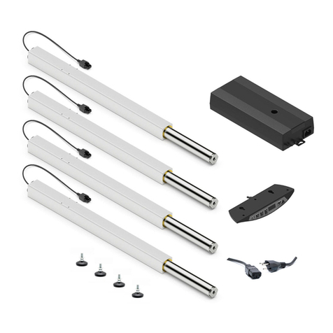
An operative spindle lifting System SL/SK/SM consists of a minimum of following components:
→Lifting column SL/SK/SM
→Control box SCT iSMPS
→Hand switch Memory
→Country specific power cable
The lifting column SL/SK/SM consists of two colorless anodized aluminium profiles which are guided with
plastic guides. The inner profile is moved by an inline spindle drive. Up to 4 spindle lifting elements can be
connected to one control box SCT4 iSMPS and be operated synchronously.
The high-performance control box SCTx iSMPS is equipped with two (SCT2) or four (SCT4) motor channels,
which are adjusted synchronously by an encoder converter. Due to the optimised driving comfort, the end
positions are gently approached as low-speed zones up to the standstill. An integrated tilt sensor reacts to
the system tipping and can prevent potentially dangerous situations. Additional functions, such as the syn-
chronisation of two control boxes or the connection of safety strips (squeezing protection) can be used.
With the hand switch Memory the lifting system can be operated comfortably, the work surface will be ad-
justed steplessly in its height.
The current height of the work surface is shown continuously on the display (in cm or inches). In addition,
up to three different memory positions can be saved and approached individually. Errors that occur are also
shown on the display.
2.2 Intended purpose use
Scope of application
NOT scope of application
→
Height adjustment of worktops
→
Height adjustment of machine parts
→
Height adjustment of profile systems
→
… the list is not exhaustive
→Clamping tool
→
Press (or counterhold for press)
→
Passenger transport
→
Security component
→
… the list is not exhaustive
2.2.1 General safety instructions
ATTENTION
The safety instructions must be paid attention to! If the system is operated improperly or not
in accordance with the intended use, there may be a risk to persons and property!
The lifting system may be used if:
→it is located in closed rooms, in a dry and non-explosive environment.
→the ambient temperature is between +10 °C and +40 °C.
→the relative humidity range is between 30% and 70% (non-condensing).
→there are no strong electromagnetic fields nearby.
→This device can be used by children aged 8 and over and by persons with reduced physical, sensory or
mental abilities or lack of experience and knowledge if they are supervised or have been instructed in
the safe use of the device and the resulting dangers to understand.

Operating instruction
Spindle lifting system SL/SK/SM 13xx
Document no.: B-00361
Edition 2024 02
Operating instruction EN
Copyright by Ergoswiss AG
Page 6of 29
The lifting system must not be:
→operated outside of the performance data (max. tensile, compressive, bending moment loads).
→subjected to impulse, impact and impact forces (e.g. setting down loads).
→operated with an incorrect mains voltage! Adhere to the type plate of the control box!
→designed for continuous operation (below the duty cycle ratio of 2/40).
→operated on unstable or sloping ground.
→operated with impermissible or non-designated components.
(e.g. different types of lifting elements; replacement of the control (control software))
→operated with damaged components.
→opened, reworked or rebuilt.
→operated if the power cable is not freely accessible. Disconnect the power cord in the event of a fault.
→Children must not play with the device. Cleaning and user maintenance shall not be made by children
without supervision.
When installing and operating the lifting system, the intended use of the entire system must be adhered to.
Commissioning is prohibited until the entire system complies with the provisions of the EC Directives
2006/42/EC (Machinery Directive). For this purpose, it is essential to perform a risk analysis, so that possible
residual hazards can be reacted to (e.g. through constructive measures or through instructions in the oper-
ating instructions and/or through safety indication on the system). In the event of improper use, the liability
of Ergoswiss AG and the general operating permit for the lifting system will expire.
2.3 Target group and prior knowledge
Before installing and operating the lifting system, this operating instruction must be read and understood.
The manual must be kept in close proximity to the system for future reference.
This operating instruction addresses the following groups of people:
The manufacturer of the overall system who integrates this lifting system into an overall system and
integrates these operating instructions into the operating instructions for the overall system.
The commissioning personnel who install the lifting system in a workplace, a machine, etc. and put it
into operation. For commissioning basic mechanical and electrical knowledge are required.

Operating instruction
Spindle lifting system SL/SK/SM 13xx
Document no.: B-00361
Edition 2024 02
Operating instruction EN
Copyright by Ergoswiss AG
Page 7of 29
2.4 Performance characteristics
2.4.1 Lifting column SL/SK/SM 13xx
Lifting column SL/SK 13xx
Lifting column SM 13xx
Cross-section
260 x 60 mm
(10.23” x 2.36”)
150 x 70 mm
(5.91” x 2.76”)
Standard stroke length
300, 400 mm (12”, 16”)
Installation length
Stroke length + 230 mm (9”)
Lower block position = stroke length + 227 mm (8.9”)
Weight
SL 1330 = 9.5 kg
(20.9 lbs)
SL 1340 = 10.9 kg
(24.0 lbs)
SK 1330 = 9.9 kg
(21.8 lbs)
SK 1340 = 11.3 kg
(24.9 lbs)
SM 1330 = 8.1 kg
(17.9 lbs)
SM 1340 = 9.2 kg
(20.3 lbs)
Max. allowed pressure
load
3’000 N
(674 lbf)
Max. allowed tensile load
FTensile stat. 500 N
(112 lbf)
; FTensile dyn. 50 N
(11 lbf)
Power consumption
2-6.5 A per lifting column (load dependent)
Voltage
24 V
Lifting speed
6 – 8.5 mm/s
(0.24 – 0.33 ’’/s)
(load dependent)
Noise level
< 60 dBA
Protection class
(DIN EN 60529)
IP 30
Electrical connection Molex MiniFit plug 8 Pin
Cable length 1’800 m (71”)
End switch
No (reading Encoder)
Tested product life
5’000 cycles with 400 mm
(16’’)
stroke length
3’000 N
(674 lbf)
pressure load, duty cycle 2/40
dyn. = during the lifting movement
Duty Cycle 2/40; operating max. 2 min, pause 40 min

Operating instruction
Spindle lifting system SL/SK/SM 13xx
Document no.: B-00361
Edition 2024 02
Operating instruction EN
Copyright by Ergoswiss AG
Page 8of 29
Max. allowed bending moment
Lifting column SL/SK
Max. allowed bending moment
Lifting column SM
Mbxstat.
1’200 Nm
(885 lbf⋅ft)
Mbystat.
450 Nm
(332 lbf⋅ft)
Mbxdyn.
550 Nm
(406 lbf⋅ft)
Mbydyn.
200 Nm
(148 lbf
⋅
ft)
Mbxstat.
900 Nm
(664 lbf⋅ft)
Mbystat.
350 Nm
(258 lbf⋅ft)
Mbxdyn.
450 Nm
(332 lbf⋅ft)
Mbydyn.
150 Nm
(111 lbf
⋅
ft)
Mbx = force x stroke
Mby = force x stroke
Mbx = force x stroke
Mby = force x stroke
stat. = during standstill; dyn. = during stroke movement
2.4.2 Control box SCT2 iSMPS and SCT4 iSMPS
Dimension (L x B x H)
309 x 120 x 55 mm
(12.2” x 4.7” x 2.2”)
Weight
SCT2: 1.12 kg
(2.47 lbs)
SCT4: 1.24 kg
(2.73 lbs)
Supply voltage
EU: 207 – 254.4 V 50 Hz 4.5 A
US: 103.5 – 127.2 V 60 Hz 7.4 A
Primary standby power
< 0.6 W
Power
580 VA ; 20 A @ 29 V DC
Protection class (DIN EN 60529)
IP 20
Performance Level (DIN EN 13849-1)
PL b
2.4.3 Hand switch Up/Down and Memory
Electrical connection
RJ-12 plug 6 Pin
Cable length 2 m (79”)
Protection class (DIN EN 60529) IP 30
Stroke
Mbx
Force
Stroke
Mby
Force
Stroke
Force
Mbx
Stroke
Force
Mby
Bending moment of Lifting column SL/SK
F
orce
[N]
Stroke [mm]
F
orce
[N]
Stroke [mm]
Bending moment of Lifting column SM

Operating instruction
Spindle lifting system SL/SK/SM 13xx
Document no.: B-00361
Edition 2024 02
Operating instruction EN
Copyright by Ergoswiss AG
Page 9of 29
2.4.4 System data
# spindle
column
Max. system
load
Stroke
length
Lifting
element
Control box
SCT iSMPS
Lifting speed
Duty
cycle
[kg]
(lbs)
[mm]
(in)
Typ
230 V
110 V
[On/Off]
1 300
(660)
300
(12’’)
1330 V1401 V3401
6 – 8.5 mm/s
(
0.24 - 0.33 "/s)
Load dependent
2/40
min
400
(16’’)
1340 V1400 V3400
2 600
(1’320)
300
(12’’)
1330 V1401 V3401
400
(16’’)
1340 V1400 V3400
3 750
(1’650)
300
(12’’)
1330 V1401 V3401
400
(16’’)
1340 V1400 V3400
4 1’000
(2’200)
300
(12’’)
1330
V1401
V3401
400
(16’’)
1340 V1400 V3400
5 1’100
(2’425)
300
(12’’)
1330 2x V1401 2x V3401
400
(16’’)
1340 2x V1400 2x V3400
6 1’200
(2’645)
300
(12’’)
1330 2x V1401 2x V3401
400
(16’’)
1340 2x V1400 2x V3400
7 1’300
(2’865)
300
(12’’)
1330
2x V1401
2x V3401
400
(16’’)
1340 2x V1400 2x V3400
8 1’500
(3’300)
300
(12’’)
1330 2x V1401 2x V3401
400
(16’’)
1340 2x V1400 2x V3400
Lifting column SL, SK or SM
Duty cycle 2/40; operating max. 2 min, pause 40 min
NOTE
The lifting system can be subjected to uneven loads as long …
→
the max. load on the single lifting element is not exceeded,
→
the max. bending torque of the lifting element is not exceeded,
→
the entire system is located on sufficient safe ground
… and the entire plant has been constructed in accordance with the provisions of the mechan-
ical equilibrium. Conducting a risk analysis
ATTENTION
High pulse / impact forces due to the discontinuation of loads are not allowed.
(e.g. discontinuation of loads in feed with crane or forklift)

Operating instruction
Spindle lifting system SL/SK/SM 13xx
Document no.: B-00361
Edition 2024 02
Operating instruction EN
Copyright by Ergoswiss AG
Page 10 of 29
3Mounting instructions
3.1 Mounting instructions Lifting column
NOTE
The lifting system must be mounted in such a way, that driving to the lower position is possi-
ble at any time.
Otherwise, no initial operating and reset of the system can be carried out.
Mounting on top
Adaptor plate with slot hole
(Screw size M8)
Mounting on T-slot (Cross bar)
Outer profile with T-slots
Mounting at bottom
Inner profile
4x Screw M6x20 self-tapping
(included in scope of delivery)
Motor cable 1’800 mm
(71’’)
With up to 5x Motor extension cable of 1’200 mm (47”)
can be extended up to 7’800 mm
(307”)

Operating instruction
Spindle lifting system SL/SK/SM 13xx
Document no.: B-00361
Edition 2024 02
Operating instruction EN
Copyright by Ergoswiss AG
Page 11 of 29
Lifting column Type SL/SK
Adaptor plate (Top)
2x Slot hole
for screw size M8
(drawing in mm)
Inner profile (Bottom)
4x Through hole
for screw size M6 (Ø5.3)
(Ø0.2”)
Torque max. 6 Nm
(4.4 lbf⋅ft)
Screw-in depth mind. 15 mm
(0.6”)
4x Screw M6x20 self-tapping included
in the scope of delivery
(drawing in mm)
Lifting column Type
SM
Adaptor plate (Top)
2x Slot hole
for screw size M8
(drawing in mm)
Inner profile (Bottom)
4x Through hole
for screw size M6 (Ø5.3)
(Ø0.2”)
Torque max. 6 Nm
(4.4 lbf⋅ft)
Screw-in depth mind. 15 mm
(0.6”)
4x Screw M6x20 self-tapping included
in the scope of delivery
(drawing in mm)

Operating instruction
Spindle lifting system SL/SK/SM 13xx
Document no.: B-00361
Edition 2024 02
Operating instruction EN
Copyright by Ergoswiss AG
Page 12 of 29
3.2 Mounting instructions Control box
ATTENTION
During mounting of the control box the power cable needs to be disconnected from the
mains!
NOTE
The control box has an integrated tilting sensor as standard. To ensure the smooth normal
operation, the control box must be fixed rigidly to the system before initial commissioning.
(e.g. below the tabletop)
Mounting the control box at the bottom of a tabletop:
1. Place the control box to the desired location and mark the drill holes with a pen.
2. Pre-drill 3 holes (Ø 2.5 mm /
0.1’’)
.
Be careful not to drill through the table top!
3. Mount the control box with 3 screws.
(e.g.: Button head screw DIN 7981-C, Ø 3.9 mm
(0.15”)
, head-Ø 7.5 mm (
0.33’’))
.
NOTE
When tightening the screws do not exceed a maximum torque of 2 Nm
(1.5 lbf⋅ft)
!
NOTE
The motor cable has a length of 1’800 mm
(71’’)
. If needed, up to 5 motor extension cables
can be connected. They have a length of 1’200 mm
(47’’)
each.
124.00137: Extension cable Motor SCT/Compact 1.2m
(47’’)
NOTE
The cable of the hand switch has a length of 1’800 mm
(71’’)
. If needed it can be expanded
with up to 3 extension cables. They have a length of 1’000 mm
(39’’)
each.
124.00290: Extension cable Hand switch SCT 1m
(39’’)

Operating instruction
Spindle lifting system SL/SK/SM 13xx
Document no.: B-00361
Edition 2024 02
Operating instruction EN
Copyright by Ergoswiss AG
Page 13 of 29
Control box SCT4 iSMPS
Control box SCT2 iSMPS
ATTENTION
Connecting homemade products to the control box is prohibited!
Only use supplied components.
4. Connect the motor cables to the lifting columns.
5. Connect the motor cables to the control box in the correct order from 1to 4.
(Automatic plug detection on all sockets)
6. Connect the hand switch to the control box.
If necessary, optional components can now be connected (e.g. safety strips, sync cable).
7. Connect the power cable to the control box.
NOTE
Before connecting the power cable to the mains the following must be verified:
→ Does the mains voltage correspond to the value on the name plate of the control box?
→ Are the plugs of the motor cable connected to the correct sockets (1to 4)?
→ Is the entire lifting system assembled according to the assembly instructions?
8. Connect power cable to the mains.
Connection for Safety strip
Connection for Hand switch
Connection for Sync cable
Motor socket 1
Motor socket 2
Motor socket 3
Motor socket 4

Operating instruction
Spindle lifting system SL/SK/SM 13xx
Document no.: B-00361
Edition 2024 02
Operating instruction EN
Copyright by Ergoswiss AG
Page 14 of 29
3.3 Mounting instructions Hand switch
3.3.1 Hand switch Memory
1. Position the hand switch underneath the table plate.
The control panel must overhang below the work sur-
face!
2. Fasten the hand switch using the mounting screws.
Be careful not to drill through the table top!
3.3.2 Hand switch Up-Down
1. Position the hand switch underneath the table plate.
The control panel must overhang below the work sur-
face!
2. Fasten the hand switch using the mounting screws.
Be careful not to drill through the table top!

Operating instruction
Spindle lifting system SL/SK/SM 13xx
Document no.: B-00361
Edition 2024 02
Operating instruction EN
Copyright by Ergoswiss AG
Page 15 of 29
4Initial operation
ATTENTION
Danger of squeezing during height adjustment!
ATTENTION
It must be possible to fully retract the lifting element to its lower block position at any time
(also in the operating state).
If the lifting element cannot retract completely and hits a stop before it reached its lower
block position, the zero position is set incorrectly. This leads to a collision when moving up to
the upper block position.
ATTENTION
The system may only be fully loaded after the initial operation has been completed.
During the initial operation, the lifting system may be loaded with max. 50% of the system
load.
NOTE
During the initial operation, the lifting system drives with half the speed.
1. Keep the buttons and pressed simultaneously to drive the lower block position.
The system moves downwards at half speed. Upward movement is disabled.
2. After reaching the block position, the system will drive out a few millimeters.
Afterwards the control box will emit 3 signal sounds.
3. let go of the buttons and .
After reaching the block position, the lower and the upper position will be stored automatically.
The initial operation is completed.
NOTE
The lower position is 3 mm (0.12’’) higher than the block position. The upper position depends
on the lifting element type, resp. of the control box software.
4.1 Plug detection
The control box can detect whether a lifting element is plugged into the relevant socket.
The control box only recognizes during the lifting movement whether a lifting element has been removed.
After plugging out or replacing a lifting element the system must be reset to synchronize all connected lifting
elements.
4.2 Duty cycle monitoring
The duty cycle monitoring checks the ratio between the operation time and standstill time. To avoid over-
heating of the system a duty cycle of 2/40 (ON/OFF) should be maintained.
The maximum continuous operating time is 2 minutes. Afterwards a pause of at least 40 minutes needs to
be observed before the system can be operated again.

Operating instruction
Spindle lifting system SL/SK/SM 13xx
Document no.: B-00361
Edition 2024 02
Operating instruction EN
Copyright by Ergoswiss AG
Page 16 of 29
5Operation with Hand switch Type Memory
5.1 Drive Up / Down
This function is used for easy height adjustment of the system.
Press the button or .
Keep the button pressed until the desired working height is reached.
5.2 Saving and approaching a memory position
With this function it is possible to memorise a certain position/height and approach it at a later time by
pushing one button. With the 3 memory buttons up to 3 different positions can be stored and approached.
1. Drive to the desired position and press the button M3 times.
2. Press one of the buttons
1
2
3
within 5 seconds.
After saving the control box will emit 1 signal sound.
The memory position is now stored under the pressed button.
To approach a stored memory position:
Keep one of the buttons
1
2
3
pressed until the desired working height is reached.

Operating instruction
Spindle lifting system SL/SK/SM 13xx
Document no.: B-00361
Edition 2024 02
Operating instruction EN
Copyright by Ergoswiss AG
Page 17 of 29
5.3 Limit the stroke length (Container-Stop/Shelf-Stop)
These two features can be used to limit the stroke length of the lifting system (e.g. if a container is under
the table).
NOTE
The Shelf-Stop position limits the upper end position.
The Container-Stop position limits the lower end position.
5.3.1 Limit upper end position - Shelf-Stop «S 04»
To define a Shelf-Stop position, proceed as follows:
1. Keep the buttons
1
2
and pressed simultaneously for 4 seconds.
The display shows «S 01», while the «S» is blinking.
2. Press the button or until «S 04» is selected.
3. Confirm the selection «S 04» with the button M.
The display stops blinking.
4. Press the button or to drive to the desired Shelf-Stop position.
5. Confirm with the button M.
The display shows «S 04».
6. Press the button
1
2
or
3
to leave the menu mode.
NOTE
To delete a set Shelf-stop position, a new one has to be done with the same procedure.
5.3.2 Limit lower end position – Container-Stop «S 05»
To define a Container-Stop position, proceed as follows:
1. Keep the buttons
1
2
and pressed simultaneously for 4 seconds.
The display shows «S 01», while the «S» is blinking.
2. Press the button or until «S 05» is selected.
3. Confirm the selection «S 05» with the button M.
The display stops blinking.
4. Press the button or to drive to the desired Container-Stop position.
5. Confirm with the button M.
The display shows «S 05».
6. Press the button
1
2
or
3
to leave the menu mode.
NOTE
To delete a set Container-stop position, a new one has to be done with the same procedure.

Operating instruction
Spindle lifting system SL/SK/SM 13xx
Document no.: B-00361
Edition 2024 02
Operating instruction EN
Copyright by Ergoswiss AG
Page 18 of 29
5.4 Setting the shown height on the display «S 06»
The displayed height can be adjusted with this feature.
1. Keep the buttons
1
2
and pressed simultaneously for 4 seconds.
The display shows «S 01», while the «S» is blinking.
2. Press the button or until «S 06» is selected.
3. Confirm the selection «S 06» with the button M.
The display shows the current height, while the «cm» is blinking.
4. Measure the height of the table.
5. Press the button or to adjust the measured height.
6. Confirm with the button M.
7. Press the button
1
2
or
3
to leave the menu mode.
5.5 Changing the displayed unit of measurement (cm/inch) «S 07»
This function can be used to change the height unit on the display from «cm» to «inch» or from «inch» to
«cm».
1. Keep the buttons
1
2
and pressed simultaneously for 4 seconds.
The display shows «S 01», while the «S» is blinking.
2. Press the button or until «S 07» is selected.
3. Confirm the selection «S 07» with the button M.
The display blinks «cm» or «inch».
4. Press the button or to select the desired measurement unit.
5. Confirm with the button M.
6. Press the button
1
2
or
3
to leave the menu mode.
The unit of measurement on the display has now been changed from centimeters (cm) to inches (inch) or
from inches to centimeters (2.54 cm = 1 inch).

Operating instruction
Spindle lifting system SL/SK/SM 13xx
Document no.: B-00361
Edition 2024 02
Operating instruction EN
Copyright by Ergoswiss AG
Page 19 of 29
5.6 Deactivating / activating the tilt sensor «S 08»
The control box has an integrated tilt sensor, which is activated by default.
The 0° inclination of the control is initialized during initial operation or reset. If the inclination of the control
exceeds 2.5° (e.g. inclined table), the control box stops the lifting movement.
After triggering the tilt sensor, the system moves back by 10 mm (0.4’’). If the inclination cannot be cor-
rected (e.g. by driving in the opposite direction), a «Reference drive» must be performed.
ATTENTION
The tilt sensor is not a safety element!
There is still a risk of injury before the tilt sensor triggers.
NOTE
In addition to a collision, the tilt sensor can be triggered by various causes. Therefore, the fol-
lowing should be observed:
Install the control box rigidly before initial operation or reset.
So that the inclination of 0° is properly initialized.
After the system is moved, the tilt sensor should be reinitialized
Perform a «Reference drive» (see chapter 5.8).
For mobile applications (e.g. table on castors), the tilt sensor should be deactivated.
This function can be used to deactivate the active tilt sensor or to reactivate the deactivated tilt sensor.
1. Keep the buttons
1
2
and pressed simultaneously for 4 seconds.
The display shows «S 01», while the «S» is blinking.
2. Press the button or until «S 08» is selected.
3. Confirm the selection «S 0» with the button M.
The control gives an acoustic signal to confirm the change;
If the tilt sensor has been deactivated, the control box will emit 3 signal sounds (short-short-long).
When the tilt sensor has been activated, the control box will emit 1 signal sound.
4. If the tilt sensor is activated, the message «E dd» appears.
For the new initialization of the tilt sensor, a «Reference drive» must now be performed.

Operating instruction
Spindle lifting system SL/SK/SM 13xx
Document no.: B-00361
Edition 2024 02
Operating instruction EN
Copyright by Ergoswiss AG
Page 20 of 29
5.7 Locking the movement (child protection)
The locking function can be used to lock the control panel of the hand switch to prevent unintentional opera-
tion of the lifting system.
By activating the locking function, the lifting system can no longer move. Neither a movement with the but-
tons or nor moving to a memory position
1
2
3
is possible.
The lifting system is in the locked state as long as it is not deactivated.
ATTENTION
The locking function is not a safety element and does not avert danger!
Activate:
Keep the buttons
1
2
and
3
pressed simultaneously for 4 seconds.
The control gives an acoustic signal to confirm the activation.
The lifting system is now locked and the display shows «E 65».
If any of the buttons on the hand switch is pressed, a signal tone sound and the system will not move.
Deactivate:
Keep the buttons
1
2
and
3
pressed simultaneously for 4 seconds.
The control gives an acoustic signal to confirm the deactivation.
The system is not locked anymore and can be operated normally.
Other manuals for SL 13 Series
1
This manual suits for next models
2
Table of contents
Other Ergoswiss Lifting System manuals

Ergoswiss
Ergoswiss SL 13 Series User manual

Ergoswiss
Ergoswiss FC 650 3.0 User manual

Ergoswiss
Ergoswiss ST 700A User manual

Ergoswiss
Ergoswiss TQ-4 User manual

Ergoswiss
Ergoswiss SLA VD Series User manual

Ergoswiss
Ergoswiss SL 14 Compact Series User manual

Ergoswiss
Ergoswiss TA-4 User manual

Ergoswiss
Ergoswiss TL-2 User manual

Ergoswiss
Ergoswiss TU-4 User manual

Ergoswiss
Ergoswiss SLA User manual