IsACQ210NMSC-0 (ENG) Rev.250708-0
6 - 16
Via dell’Industria, 20 - 42025 Cavriago (RE) Italy Tel.: +39 0522 494403
(Fig. 6)
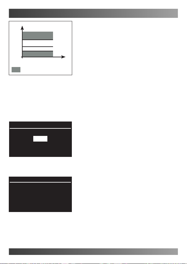
Programs
Ref. 900mS
∆MIN: ∆MAX:
100 µS 200 µS
Sockets Conrm
(Fig. 5)
Conductivity
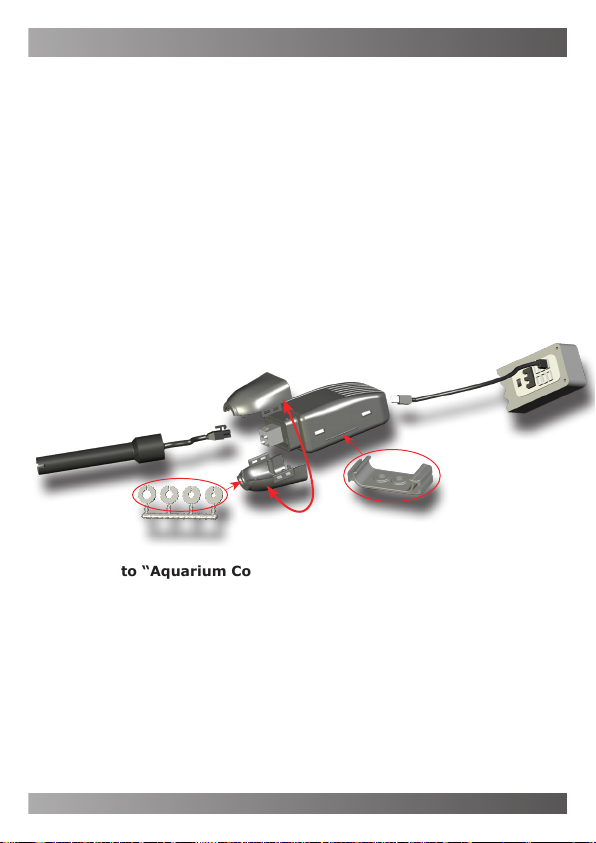
Insert
English
Programs
This option is used to create programs based on the
Conductivity value.
To set up a program, the following must be estab-
lished:
- A reference value, dened as the Conductivity for the
tank, which the system will aim to maintain.
- A ∆Max value, dened as the tolerance that must
be observed with respect to values higher than the
reference value.
For example: If the reference is set to 900mS and the
∆ Max is 200mS, the system will be enabled at values
higher than 1100mS (see chart).
- A ∆Min value, dened as the tolerance that must
be observed with respect to values lower than the
reference value.
For example: If the reference is set to 900mS and the
∆ Min is 100mS, the system will be enabled at values
lower than 800mS (see chart).
To insert a program, proceed as follows:
Main screen Main Menu Conductivity Programs.
• Select “Insert” using the keys and press “En-
ter” (Fig. 5).
Insert
In this screen, the conductivity value to obtain can be
chosen and a minimum and maximum tolerance can
be set (Ex. Fig. 6).
To set this program, proceed as follows:
Main screen Main menu Conductivity Programs
Insert.
•Select with the reference conductivity value using
the keys and set the desired value using the
keys.
•Set the “∆MIN” and “∆MAX” tolerances; select the
desired parameter using the keys and modify the
value using the keys.
•Select “Sockets” using the keys to choose
how the outputs will function when the conductivity
level goes above or below the set values. Then press
“Enter”.
•Select the output to be controlled using the keys.
The selected output will blink on both lines.
The outputs on the upper line determine which devices
must be enabled/disabled when the conductivity goes
above the set maximum value (Ref. + ∆MAX); the out-
puts on the upper line are set using the key.
900
800
1100
Conductivity
Tempo
Ref.+∆Max
Key to symbols
Values for which the system is enabled
∆Max=200mS
∆Min=100mS
Ref.
Ref.-∆Min