9 - 26
IsACQ455C-0 (ENG) Rev. 261108-0
Via dell’Industria, 20 - 42025 Cavriago (RE) Italy Tel.: +39 0522 494403
Manual controls menu
(Fig. 7)
(Fig. 8)
(Fig. 9)
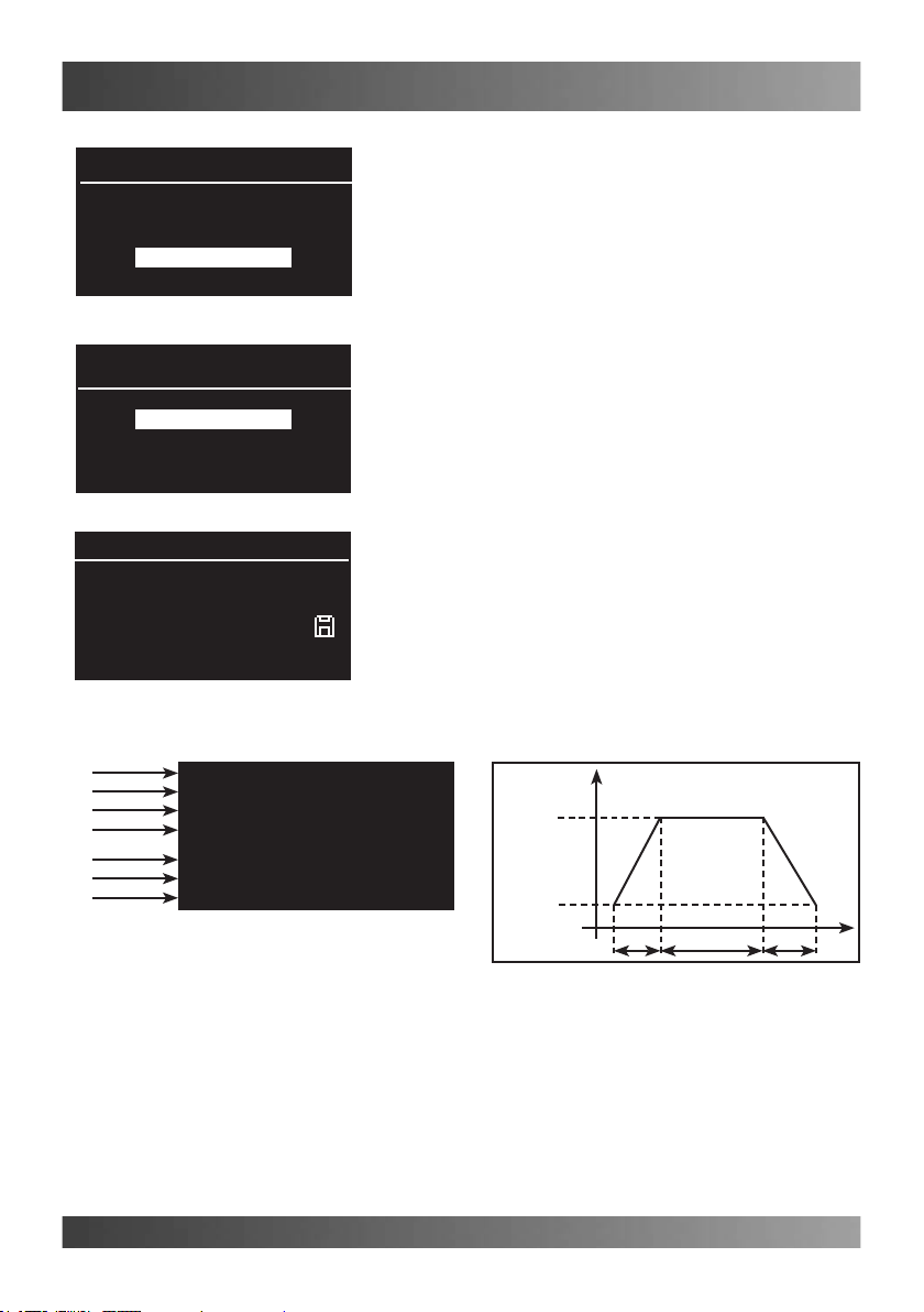
Dimmer Pompe
01: Iodio
02: Calcio
03: Plancton
Single control
P2 30%
P3 0%
P1 100%
(Fig. 10)
P4 ----
Manual controls (Single control)
Used to keep the power of each single pump at the
required value. From a minimum of 30% to a maxi-
mum of 100% (Example in Fig.8). This symbol “----”
points out that the pump is controlled according to the
set program.
Proceed as follows to select this function:
Main screen page Main menu Dimmer Pumps
Manual controls Single control.
•Select the output required using the right/left ar-
row keys and use the up/down arrow keys to
change its status; upon completion, press “Enter”.
Manual controls (All at maximum) (Fig. 9)
Used to set all the pumps at their maximum power
(100%).
Proceed as follows to use this function:
Main screen page Main menu Dimmer pumps
Manual controls All at maximum.
•Select the “All at maximum” function using the
up/down arrow keys and press “Enter”.
Manual controls (All off) (Fig. 10)
Used to switch all the pumps off simultaneously.
Proceed as follow to use this function:
Main screen page Main menu Dimmer pumps
Manual controls All off.
•Select the “All off” function using the up/down ar-
row keys and press “Enter”.
Manual controls (All at minimum) (Fig. 11)
Used to set all the pumps at their minimum power
(30%).
Proceed as follow to use this function:
Main screen page Main menu Dimmer pumps
Manual controls All at minimum.
•Select the “All at minimum” function using the up/
down arrow keys and press “Enter”.
Reset All (Fig. 12)
Used to set the pumps back at the power foreseen by
the program currently in use (----).
Proceed as follow to use this function:
Main screen page Main menu Dimmer pumps
Manual controls Reset All.
•Select the “Reset” function using the up/down arrow
keys and press “Enter”.
Dimmer pumps 1
About
Programs
Change name
Manual controls
All at maximum
P2 100%
P3 100%
P1 100%
P4 100%
All off
P2 0%
P3 0%
P1 0%
P4 0%
All at minimum
P2 30%
P3 30%
P1 30%
P4 30%
(Fig. 11)
Reset All
P2 ----
P3 ----
P1 ----
P4 ----
(Fig. 12)