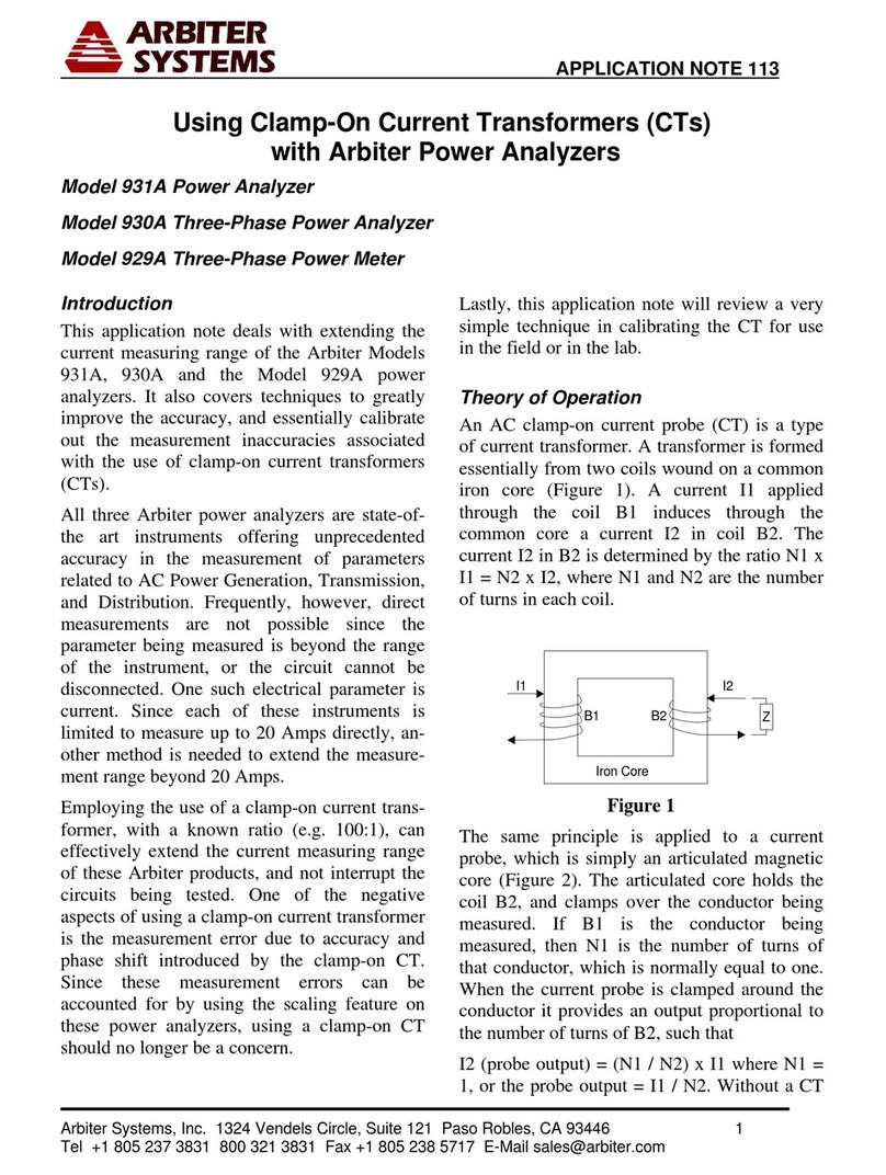
Arbiter Systems 931A User manual

Model 931A
Power System Analyzer
Operation Manual
931A POWER SYSTEM ANALYZER
CURRENT VOLTAGE
TRANSDUCER
TIMER
SETUP 1 SETUP 2 SETUP 3 SETUP 4 SETUP 5 SETUP 6
NARROW-BAND-WIDE MEAS 3 PHASE CH1 RANGE RESTART CONFIG
SHIFT HELP REVIEW PRINT LOG STORE SETUP SCALE
ESCAPE ENTER
VOLTS
AMPS
PHASE
FREQUENCY
POWER
VARS
VA
PF
HARMONICS WAVEFORM
CHANNEL 1
SELECT
CHANNEL 2
SELECT
MEASURE
HOLD
CH2 RANGE MIN
MAX
TRANSDUCER
MENU LOG DATA PRINT LAST SETUP CH1 / CH2
ON/OFF
FUSE
1AF/250V
85-264 Vac
47-440 Hz
110-250 Vdc
RS-232
GROUND
BEFORE
USE
DISPLAY
CONFIG
ARM / RESET
A B C N
750 Vrms / 1000 Vdc MAX20 Arms MAX
10Vdc
MAX
100mAdc
MAX
A B
300V
MAX
A B
Arbiter Systems, Inc.
Paso Robles, CA 93446
U.S.A.
www.arbiter.com

Description
This manual is issued for reference only, at the convenience of Arbiter
Systems. Reasonable effort was made to verify that all contents were
accurate as of the time of publication. Check with Arbiter Systems at the
address below for any revisions made since the original date of publication.
Contact Information
Arbiter Systems, Inc.
1324 Vendels Circle, Suite 121
Paso Robles, CA 93446
(805) 237-3831
www.arbiter.com
techsupp[email protected]
Definition
This manual describes the Model 931A Power System Analyzer
, and
accessories.
Firmware and Firmware Updates
This manual was created based on the following firmware:
Copyright Program: 10 February 2010
Help Version: 25 JUNE 1996
DSP Version: 093098
The firmware versions indicated above are displayed on the Model 931A
at startup. To freeze the display during this screen, press and hold
the ESCAPE key until finished viewing. Also, the 931A will issue this
information from the serial port using the VER command. See the VER
command on page 124.
Firmware Updates are available as a ROM replacement from Arbiter
Systems by contacting technical support at the information above.
ii

LIMITED WARRANTY
Arbiter Systems makes no warranty, expressed or implied, on any
product manufactured or sold by Arbiter Systems except for the following
limited warranty against defects in materials and workmanship on products
manufactured by Arbiter Systems.
Products manufactured by Arbiter Systems are guaranteed against
defective materials and workmanship under normal use and service for
one year from the date of delivery. The responsibility of Arbiter Systems
under this warranty is limited to repair or replacement, at Arbiter Systems’
option, of any product found to be defective. Arbiter Systems shall have
no liability under this warranty unless it receives written notice of any
claimed defect, within the earlier of:
Thirty days of discovery by Buyer, or;
One year from the date of delivery.
For warranty service or repair, products must be returned to a service
facility designated by Arbiter Systems. Buyer shall prepay all shipping
charges, duties, and taxes to send the product to Arbiter Systems and
Buyer shall prepay shipping charges, duties, and taxes to return the
product to Buyer.
THE WARRANTY SET FORTH HEREIN CONSTITUTES THE
ONLY WARRANTY OBLIGATIONS OF ARBITER SYSTEMS, EX-
PRESSED OR IMPLIED, STATUTORY, BY OPERATION OF LAW,
OR OTHERWISE. ARBITER SYSTEMS DISCLAIMS ANY WAR-
RANTY OF MERCHANTABILITY OR FITNESS FOR A PARTICU-
LAR PURPOSE, AND BUYER EXPRESSLY WAIVES ALL OTHER
WARRANTIES.
This limited warranty does not extend to any product, which has been
subject to:
1. Improper use or application, abuse, or operation beyond its rated
capacity, or contrary to the instructions in the operation and
maintenance manuals (if any);
2. Accident;
3. Repair or maintenance performed by Buyer, except in accordance
with the operation and maintenance manuals, if any, and any special
instructions of Arbiter Systems;
4. Modification without the prior written authorization of Arbiter
Systems (whether by the substitution of non-approved parts or
otherwise).
iii

The remedies provided herein are Buyer’s sole and exclusive remedies.
In no event shall Arbiter Systems be liable for direct, indirect, incidental
or consequential damages (including loss of profits), whether based on
contract, tort, or other legal theory.
FOR THE FASTEST POSSIBLE SERVICE, PLEASE PROCEED AS
FOLLOWS:
1. Notify Arbiter Systems, Inc., specifying the instrument model
number and serial number and giving full details of the difficulty.
Service data or instrument-return authorization will be provided
upon receipt of this information.
2. If instrument return is authorized, forward prepaid to the manufac-
turer. If it is determined that the instrument is not covered by this
warranty, an estimate will be made before the repair work begins, if
requested.
See Contact Information on page ii.
iv

Arbiter Systems, Inc.
Model 931A
Power System Analyzer
Operation Manual
Table of Contents
Chapter 1 General Information
Chapter 2 Functional Description
Chapter 3 Operation
Chapter 4 Specifications
Appendix A RS-232 Commands
Appendix B Optional Accessories
Appendix C CE Mark Certification
Index
Copyright Arbiter Systems Incorporated September 2021 All rights re-
served. International copyright secured.
PD0017400T Reorder Number: AS0094000
v

vi

Contents
1 General Information 1
1.1 Scope .............................. 1
1.2 Supplied Equipment . . . . . . . . . . . . . . . . . . . . . . 1
1.3 Available Accessories . . . . . . . . . . . . . . . . . . . . . . 2
2 Functional Description 3
2.1 Introduction........................... 3
2.2 Inputs .............................. 3
2.2.1 Voltage ......................... 3
2.2.2 Current ......................... 3
2.2.3 Transducer ....................... 5
2.2.4 Timer .......................... 5
2.3 Measurement Channels . . . . . . . . . . . . . . . . . . . . . 5
2.4 Measurement Method . . . . . . . . . . . . . . . . . . . . . 6
2.4.1 Sampling and Filtering . . . . . . . . . . . . . . . . . 8
2.5 UserInterface.......................... 8
2.5.1 Graphics Display . . . . . . . . . . . . . . . . . . . . 8
2.5.2 Keypad ......................... 9
2.6 RS-232CInterface ....................... 9
2.7 Power Supply and Battery . . . . . . . . . . . . . . . . . . . 9
2.7.1 BatteryPower ..................... 9
2.7.2 Line Power/Battery Charging . . . . . . . . . . . . . 10
2.7.3 Auto-Shutdown Mode . . . . . . . . . . . . . . . . . 11
2.8 Start-Up Sequence . . . . . . . . . . . . . . . . . . . . . . . 11
2.8.1 Holding the Start-Up Sequence . . . . . . . . . . . . 11
2.8.2 Reset – Instrument Default Setup . . . . . . . . . . 11
3 Operation 13
3.1 Introduction........................... 13
3.2 Front Panel Connections . . . . . . . . . . . . . . . . . . . . 13
vii

3.2.1 Chassis Ground . . . . . . . . . . . . . . . . . . . . . 13
3.2.2 Voltage Inputs . . . . . . . . . . . . . . . . . . . . . 14
3.2.3 Current Inputs . . . . . . . . . . . . . . . . . . . . . 14
3.2.4 Transducer Inputs . . . . . . . . . . . . . . . . . . . 15
3.2.5 Timer Inputs . . . . . . . . . . . . . . . . . . . . . . 15
3.3 FrontPanelKeys........................ 15
3.3.1 Main Functions . . . . . . . . . . . . . . . . . . . . . 15
3.3.2 Secondary Functions . . . . . . . . . . . . . . . . . . 26
3.3.3 Data Entry Functions . . . . . . . . . . . . . . . . . 41
3.3.4 Timer Control Functions . . . . . . . . . . . . . . . . 42
3.4 Front Panel Display . . . . . . . . . . . . . . . . . . . . . . 44
3.5 Direct Measurements . . . . . . . . . . . . . . . . . . . . . . 44
3.5.1 AC Voltage Measurement . . . . . . . . . . . . . . . 44
3.5.2 AC Current Measurement . . . . . . . . . . . . . . . 46
3.5.3 DC Voltage Measurement . . . . . . . . . . . . . . . 48
3.5.4 Frequency Measurement . . . . . . . . . . . . . . . . 49
3.5.5 Harmonic Measurement . . . . . . . . . . . . . . . . 50
3.6 Combined Measurements . . . . . . . . . . . . . . . . . . . 52
3.6.1 Phase Angle Measurement . . . . . . . . . . . . . . . 52
3.6.2 Active Power – Reactive Power . . . . . . . . . . . . 54
3.6.3 Apparent Power – Power Factor . . . . . . . . . . . 56
3.6.4 Waveform Display . . . . . . . . . . . . . . . . . . . 58
3.7 Timer Measurements . . . . . . . . . . . . . . . . . . . . . . 58
3.7.1 Connecting the Inputs . . . . . . . . . . . . . . . . . 59
3.7.2 Configuring the Timer . . . . . . . . . . . . . . . . . 59
3.7.3 Timer Measurement Categories . . . . . . . . . . . . 62
3.8 Transducer Testing . . . . . . . . . . . . . . . . . . . . . . . 64
3.8.1 Configuring the Transducer . . . . . . . . . . . . . . 64
3.8.2 Connecting the Inputs . . . . . . . . . . . . . . . . . 70
3.8.3 Connecting the Outputs . . . . . . . . . . . . . . . . 75
3.8.4 Performing the Measurement . . . . . . . . . . . . . 75
3.8.5 Custom Pulse, or Contact Output Tests . . . . . . . 75
3.8.6 Performing a Test . . . . . . . . . . . . . . . . . . . 80
3.9 Using External PT’s and CT’s . . . . . . . . . . . . . . . . 84
3.10DataLogging .......................... 84
3.10.1 Capturing Data . . . . . . . . . . . . . . . . . . . . . 84
3.10.2 Reviewing Data . . . . . . . . . . . . . . . . . . . . . 85
3.10.3 Erasing Logged Data . . . . . . . . . . . . . . . . . . 86
3.11 Printing / Exporting Data . . . . . . . . . . . . . . . . . . . 86
3.11.1 Print / Data Export Setup . . . . . . . . . . . . . . 86
3.11.2 ASCII Format . . . . . . . . . . . . . . . . . . . . . 87
3.11.3 Graphics Format (FX-80) . . . . . . . . . . . . . . . 87
viii

3.11.4 Bitmap ......................... 87
3.11.5 Spreadsheet . . . . . . . . . . . . . . . . . . . . . . . 88
3.11.6 Initiating Printing / Exporting . . . . . . . . . . . . 97
4 Specifications 99
4.1 Inputs .............................. 99
4.1.1 Voltage ......................... 99
4.1.2 Current ......................... 99
4.1.3 Transducer ....................... 99
4.1.4 Timer ..........................100
4.2 Measurements..........................100
4.2.1 Voltage and Current . . . . . . . . . . . . . . . . . . 100
4.2.2 PhaseAngle.......................100
4.2.3 Frequency........................101
4.2.4 Timer ..........................101
4.2.5 Transducer .......................101
4.2.6 Harmonics........................101
4.2.7 Power Quantities . . . . . . . . . . . . . . . . . . . . 101
4.3 General Specifications . . . . . . . . . . . . . . . . . . . . . 102
4.3.1 Measurement Bandwidth . . . . . . . . . . . . . . . 102
4.3.2 Memory.........................102
4.3.3 Display .........................102
4.3.4 Keypad .........................102
4.3.5 Environment . . . . . . . . . . . . . . . . . . . . . . 102
4.3.6 InputPower.......................103
4.3.7 SerialPort .......................103
A RS-232C Commands 105
A.1 Introduction...........................105
A.2 Serial Port Examples . . . . . . . . . . . . . . . . . . . . . . 106
A.3 Command Summary . . . . . . . . . . . . . . . . . . . . . . 107
A.3.1 Battery Charging Status (BAT) . . . . . . . . . . . 107
A.3.2 Backlight Set (BLT) . . . . . . . . . . . . . . . . . . 107
A.3.3 Channel Calibrate (CCH) . . . . . . . . . . . . . . . 107
A.3.4 Ratio CH1/CH2 (CCR) . . . . . . . . . . . . . . . . 108
A.3.5 Channel Input Select (CHS) . . . . . . . . . . . . . . 108
A.3.6 Calibrate Input (CIN) . . . . . . . . . . . . . . . . . 109
A.3.7 Transducer Configuration (COT) . . . . . . . . . . . 109
A.3.8 Daylight Saving Time, Set (DAY) . . . . . . . . . . 110
A.3.9 Display Dump, ASCII (DDA) . . . . . . . . . . . . . 110
A.3.10 Data Dump, Bitmapped (DDB) . . . . . . . . . . . 111
A.3.11 Store Calibration Data in EEPROM (EEP) . . . . . 111
ix

A.3.12 DSP Frequency Calibrate (FRD) . . . . . . . . . . . 111
A.3.13 Frequency, Return (FRQ) . . . . . . . . . . . . . . . 111
A.3.14 Timer Calibrate (FTM) . . . . . . . . . . . . . . . . 112
A.3.15 Harmonics Display (HAR) . . . . . . . . . . . . . . . 112
A.3.16 Harmonic Magnitude, Return (HMA) . . . . . . . . 112
A.3.17 Harmonic Phase Angle, Return (HPH) . . . . . . . . 113
A.3.18 Power Down (KIL) . . . . . . . . . . . . . . . . . . . 113
A.3.19 Log Data (LOG) . . . . . . . . . . . . . . . . . . . . 113
A.3.20 Last Setup (LSU) . . . . . . . . . . . . . . . . . . . 113
A.3.21 Magnitude (Channel), Return (MAG) . . . . . . . . 114
A.3.22 Measure Hold (MHD) . . . . . . . . . . . . . . . . . 114
A.3.23 MIN/MAX, Display (MMN) . . . . . . . . . . . . . 114
A.3.24 Bandwidth-Narrow, Set (NAB) . . . . . . . . . . . . 114
A.3.25 Overload Status (OVD) . . . . . . . . . . . . . . . . 115
A.3.26 Phase/Frequency Display (P F) . . . . . . . . . . . . 115
A.3.27 Power/Vars Display (P V) . . . . . . . . . . . . . . . 115
A.3.28 Power Factor, Return (PFA) . . . . . . . . . . . . . 115
A.3.29 Phase Mode, Set (PHM) . . . . . . . . . . . . . . . . 116
A.3.30 Phase, Return (PHS) . . . . . . . . . . . . . . . . . 116
A.3.31 Power, Return (PWR) . . . . . . . . . . . . . . . . . 116
A.3.32 Range Hold, Set (RHD) . . . . . . . . . . . . . . . . 117
A.3.33 Logged Data, Review (RLD) . . . . . . . . . . . . . 117
A.3.34 Range Hold, Release (RRH) . . . . . . . . . . . . . . 117
A.3.35 MIN/MAX, Restart (RST) . . . . . . . . . . . . . . 117
A.3.36 Transducer Channel (SCC) . . . . . . . . . . . . . . 118
A.3.37 Serial Number (SER) . . . . . . . . . . . . . . . . . 118
A.3.38 Flash Log (SLO) . . . . . . . . . . . . . . . . . . . . 118
A.3.39 Scale On/Off (SOO) . . . . . . . . . . . . . . . . . . 119
A.3.40 DSP Speed (SPD) . . . . . . . . . . . . . . . . . . . 119
A.3.41 Phase Preference, Set (SPH) . . . . . . . . . . . . . 119
A.3.42 Range, Set (SRG) . . . . . . . . . . . . . . . . . . . 120
A.3.43 Scale Factors, Set or Return (SSC) . . . . . . . . . . 120
A.3.44 Store Setup (SST) . . . . . . . . . . . . . . . . . . . 121
A.3.45 Setup, Recall (SUP) . . . . . . . . . . . . . . . . . . 121
A.3.46 Timer, Arm (TAM) . . . . . . . . . . . . . . . . . . 121
A.3.47 Time, Return (TDR) . . . . . . . . . . . . . . . . . . 121
A.3.48 Time, Set (TDS) . . . . . . . . . . . . . . . . . . . . 121
A.3.49 Timer Configuration, Set or Return (TCF) . . . . . 122
A.3.50 Transducer Display (TDU) . . . . . . . . . . . . . . 122
A.3.51 Timer Display (TIM) . . . . . . . . . . . . . . . . . 123
A.3.52 Timer Reading, Return (TMR) . . . . . . . . . . . . 123
A.3.53 Timer, Reset (TRS) . . . . . . . . . . . . . . . . . . 123
x
A.3.54 Timer, Stop (TSP) . . . . . . . . . . . . . . . . . . . 123
A.3.55 Timer, Start (TST) . . . . . . . . . . . . . . . . . . 123
A.3.56 Volts/Amps Display (V A) . . . . . . . . . . . . . . 123
A.3.57 VA/PF Display (V P) . . . . . . . . . . . . . . . . . 124
A.3.58 Volt-Amps, Return (VAM) . . . . . . . . . . . . . . 124
A.3.59 VARS, Return (VAR) . . . . . . . . . . . . . . . . . 124
A.3.60 Version, Return (VER) . . . . . . . . . . . . . . . . 124
A.3.61 Waveform Display (WAV) . . . . . . . . . . . . . . . 125
A.3.62 Bandwidth Wide, Set (WIB) . . . . . . . . . . . . . 125
A.3.63 Transducer Input, Display (XDI) . . . . . . . . . . . 125
A.3.64 Transducer Output, Display (XDO) . . . . . . . . . 125
B Optional Accessories 127
B.1 Precision Current Transformer . . . . . . . . . . . . . . . . 127
B.1.1 Specifications . . . . . . . . . . . . . . . . . . . . . . 127
B.1.2 Input Connections . . . . . . . . . . . . . . . . . . . 127
B.1.3 Current Display . . . . . . . . . . . . . . . . . . . . 128
B.2 Handle/Bail...........................128
B.2.1 Parts and Accessories . . . . . . . . . . . . . . . . . 128
B.2.2 Required Tools . . . . . . . . . . . . . . . . . . . . . 128
B.2.3 Procedure........................128
B.2.4 Operation........................128
B.3 ExtendedMemory .......................129
B.3.1 Data Organization . . . . . . . . . . . . . . . . . . . 130
B.3.2 Computing the Number of Files and Records . . . . 132
B.3.3 Log Data Triggering . . . . . . . . . . . . . . . . . . 133
B.3.4 Front Panel Operation . . . . . . . . . . . . . . . . . 134
B.3.5 Remote Operation . . . . . . . . . . . . . . . . . . . 135
B.3.6 Setup of Logged Data Operation . . . . . . . . . . . 135
B.3.7 Review of Logged Data . . . . . . . . . . . . . . . . 137
B.3.8 Trigger Remote Data Logging . . . . . . . . . . . . . 138
C CE Mark Certification 139
xi

xii

List of Figures
2.1 Model 931A Front Panel . . . . . . . . . . . . . . . . . . . . 4
2.2 Input Multiplexing . . . . . . . . . . . . . . . . . . . . . . . 5
3.1 Phase, Power Factor, and VAR Definitions . . . . . . . . . . 19
3.2 Phase, Power Factor, VAR Quadrants . . . . . . . . . . . . 20
3.3 Three-Phase Measurement Selection . . . . . . . . . . . . . 28
3.4 Three Phase Display Selection . . . . . . . . . . . . . . . . . 28
3.5 Three Phase Tabular Display . . . . . . . . . . . . . . . . . 28
3.6 Three-Phase Displays for an ABC System . . . . . . . . . . 32
3.7 Three-Phase Displays for a CBA System . . . . . . . . . . . 33
3.8 1-Phase, 2-Wire, 1-Element Connections . . . . . . . . . . . 34
3.9 1-Phase, 3-Wire, 2-Element Connections . . . . . . . . . . . 34
3.10 3-Phase, 3-Wire, 2-Element Connections . . . . . . . . . . . 35
3.11 3-Phase, 4-Wire, 2.5-Element Connections . . . . . . . . . . 35
3.12 3-Phase, 4-Wire, 3-Element Connections . . . . . . . . . . . 36
3.13 Phase Angle Example . . . . . . . . . . . . . . . . . . . . . 54
3.14 1-Phase, 2-Wire, 1-Element Transducer Test . . . . . . . . . 71
3.15 1-Phase, 3-Wire, 2-Element Transducer Test . . . . . . . . . 72
3.16 3-Phase, 4-Wire, 2.5-Element Transducer Test . . . . . . . . 73
3.17 3-Phase, 4-Wire, 3-Element Transducer Test . . . . . . . . . 74
3.18 3-Phase, 4-Wire, 3-Element Custom Pulse Transducer Test 83
B.1 Model 931A Case with Handle/Bail . . . . . . . . . . . . . 129
xiii

xiv

List of Tables
2.1 AC Measurement Configurations . . . . . . . . . . . . . . . 6
2.2 DC Measurement Configurations . . . . . . . . . . . . . . . 7
2.3 RS-232C Port Pinout / Signal Description . . . . . . . . . . 10
2.4 931A Reset Selection Screen . . . . . . . . . . . . . . . . . . 12
3.1 Phase Angle Preferences . . . . . . . . . . . . . . . . . . . . 20
3.2 Channel 2, AC Voltage Ranges, Vrms . . . . . . . . . . . . 23
3.3 Channel 2, AC Current Ranges, Arms . . . . . . . . . . . . 23
3.4 Channel 2, DC Voltage Ranges, Vdc . . . . . . . . . . . . . 23
3.5 Channel 1, AC Voltage Ranges, Vrms . . . . . . . . . . . . 37
3.6 Channel 1, AC Current Ranges, Arms . . . . . . . . . . . . 37
3.7 Channel 1, DC Voltage Ranges, Vdc . . . . . . . . . . . . . 37
3.8 Phase Convention . . . . . . . . . . . . . . . . . . . . . . . . 54
B.1 Custom Data Table . . . . . . . . . . . . . . . . . . . . . . . 132
xv

xvi

Chapter 1
General Information
1.1 Scope
The Arbiter Systems Model 931A Power System Analyzer is a state-of-the-
art instrument offering unprecedented accuracy in the measurement of pa-
rameters related to AC Power Generation, Transmission, and Distribution.
Using Arbiter’s proprietary PowerDSA
Digital Signal Processing (DSP)
circuitry, the Model 931A greatly enhances the precision measurement of
these AC parameters. Powered by either an internal rechargeable battery
or by AC line voltage, the Model 931A is truly portable. This manual is
divided into four chapters and two appendices as follows:
Chapter 1. General Information
Chapter 2. Functional Description
Chapter 3. Operation
Chapter 4. Specifications
Appendix A. RS-232C Commands
Appendix B. Optional Accessories
1.2 Supplied Equipment
The Model 931A is supplied with a standard AC Power Cord (P09R), RS-
232 Null-Modem Cable (P/N CA0019806), Safety Ground Lead (812HA-8)
and one Operations Manual (AS0094000).
1

1.3 Available Accessories
The following accessories are available for use with the Model 931A:
Model Number Description
931A/01 16-Megabyte internal memory
AS0060000 PowerCSV, Applications software (download only).
Requires Option 01
AS0035901 Adjustable handle/bail Assembly
09311A 400 Amp 20:1 precision CT, 0.1% accuracy.
Includes AS0036000 Mounting Bracket
AP0012800 1000:1 Clamp-on CT, 200 Amps
AP0012900 250:5, 500:5, 1000:5 Clamp-on CT, 1000 Amps
AP0001300 1000:1; 1000A, 600V, Cat. III, EN61010
811AT/CT* 3-Phase Universal Test Plug Current Lead Set
813AT/BT* 3-Phase Safety Voltage Lead Set
815AT/BT* 3-Phase Fused Voltage Lead Set
816AT/CT* 3-Phase Spade-lug Current Lead Set
817AT* 3-Phase CT Lead Set: red, yellow, blue
* This is a partial list. Other high-quality test leads and accessories are
also available. Contact Arbiter Systems for further information.
2

Chapter 2
Functional Description
2.1 Introduction
The following paragraphs provide a brief functional description of some
Model 931A components. Figure 2.1 illustrates the front panel.
2.2 Inputs
2.2.1 Voltage
Measure AC or DC voltages through four color-coded insulated banana
jacks on the front panel. Labeled A, B, C, and N, each terminal can
accept input voltages of up to 750 Vrms or 1000 Vdc. Each input voltage
terminal is isolated from signal common with an impedance of 1 megohm,
and is physically isolated from the chassis.
2.2.2 Current
The 931A features three independent, transformer-coupled AC current
inputs, accessible via three pairs of front-panel binding posts, which are
color-coded for polarity and labeled A, B, and C.
Each terminal can accept an AC signal with a rms current value of up
to 20 amps. All current inputs are isolated to withstand a potential of
1000 Vpeak from chassis ground.
3

931A POWER SYSTEM ANALYZER
CURRENT VOLTAGE
TRANSDUCER
TIMER
SETUP 1 SETUP 2 SETUP 3 SETUP 4 SETUP 5 SETUP 6
NARROW-BAND-WIDE MEAS 3 PHASE CH1 RANGE RESTART CONFIG
SHIFT HELP REVIEW PRINT LOG STORE SETUP SCALE
ESCAPE ENTER
VOLTS
AMPS
PHASE
FREQUENCY
POWER
VARS
VA
PF
HARMONICS WAVEFORM
CHANNEL 1
SELECT
CHANNEL 2
SELECT
MEASURE
HOLD
CH2 RANGE MIN
MAX
TRANSDUCER
MENU LOG DATA PRINT LAST SETUP CH1 / CH2
ON/OFF
FUSE
1AF/250V
85-264 Vac
47-440 Hz
110-250 Vdc
RS-232
GROUND
BEFORE
USE
DISPLAY
CONFIG
ARM / RESET
A B C N
750 Vrms / 1000 Vdc MAX20 Arms MAX
10Vdc
MAX
100mAdc
MAX
A B
300V
MAX
A B
Figure 2.1: Model 931A Front Panel
4
Other manuals for 931A
1
Table of contents
Other Arbiter Systems Measuring Instrument manuals

Arbiter Systems
Arbiter Systems 1092A User manual

Arbiter Systems
Arbiter Systems 931A Installation and operating instructions

Arbiter Systems
Arbiter Systems 940A User manual

Arbiter Systems
Arbiter Systems 1133A User manual

Arbiter Systems
Arbiter Systems 1040C Installation guide

Arbiter Systems
Arbiter Systems 921A Guide

Arbiter Systems
Arbiter Systems 940A User manual

Arbiter Systems
Arbiter Systems Portable Power Sentinel 933A User manual