Arbiter Systems 940A User manual

MODEL 940A
TIMING SYSTEM ANALYZER
USER’S MANUAL
Arbiter Systems, Inc.
Paso Robles, CA 93446
U.S.A.
FONKEL MEXICANA
Tel: (55) 55 33 61 14
informes@fonkel.com.mx
www.fonkel.com.mx

Notice
This manual is issued for reference only, at the convenience of Ar-
biter Systems. Reasonable effort was made to verify that all con-
tents were accurate as of the time of publication. Check with Ar-
biter Systems at the address below for any revisions made since the
original date of publication, found on page v.
ii

LIMITED WARRANTY
Arbiter Systems makes no warranty, expressed or implied, on any
product manufactured or sold by Arbiter Systems except for the
following limited warranty against defects in materials and work-
manship on products manufactured by Arbiter Systems.
Products manufactured by Arbiter Systems are guaranteed against
defective materials and workmanship under normal use and service
for one year from the date of delivery. The responsibility of Arbiter
Systems under this warranty is limited to repair or replacement,
at Arbiter Systems’ option, of any product found to be defective.
Arbiter Systems shall have no liability under this warranty unless
it receives written notice of any claimed defect, within the earlier
of:
•Thirty days of discovery by Buyer, or;
•One year from the date of delivery.
For warranty service or repair, products must be returned to a
service facility designated by Arbiter Systems. Buyer shall prepay
all shipping charges to Arbiter Systems, and Arbiter Systems shall
pay shipping charges, via ground, incurred in returning the product
to Buyer. However, Buyer shall pay all shipping charges, duties and
taxes for products returned to Buyer in a country other than the
United States of America.
THE WARRANTY SET FORTH HEREIN CONSTITUTES
THE ONLY WARRANTY OBLIGATIONS OF ARBITER
SYSTEMS, EXPRESSED OR IMPLIED, STATUTORY, BY
OPERATION OF LAW, OR OTHERWISE. ARBITER
SYSTEMS DISCLAIMS ANY WARRANTY OF
MERCHANTABILITY OR FITNESS FOR A PARTICULAR
PURPOSE, AND BUYER EXPRESSLY WAIVES ALL OTHER
WARRANTIES.
This limited warranty does not extend to any product, which has
been subject to:
I Improper use or application, abuse, or operation beyond its
rated capacity, or contrary to the instructions in the operation
and maintenance manuals (if any);
II Accident;
III Repair or maintenance performed by Buyer, except in accor-
dance with the operation and maintenance manuals, if any,
and any special instructions of Arbiter Systems;
IV Modification without the prior written authorization of Ar-
biter Systems (whether by the substitution of non-approved
iii

parts or otherwise).
The remedies provided herein are Buyer’s sole and exclusive reme-
dies. In no event shall Arbiter Systems be liable for direct, indi-
rect, incidental or consequential damages (including loss of profits),
whether based on contract, tort, or other legal theory.
FOR THE FASTEST POSSIBLE SERVICE,
PLEASE PROCEED AS FOLLOWS:
1. Notify Arbiter Systems, Inc., specifying the instrument model
number and serial number and giving full details of the dif-
ficulty. Service data or instrument-return authorization will
be provided upon receipt of this information.
2. If instrument return is authorized, forward prepaid to the
manufacturer. If it is determined that the instrument is not
covered by this warranty, an estimate will be made before the
repair work begins, if requested.
See Contact Information on page ii.
iv

Arbiter Systems, Inc.
Model 940A
Timing System Analyzer™
User’s Manual
Notice & Contact
Warranty
Contents
Features
Connecting Timing Signals
Setup Screens
Viewing Timecodes
Specifications
940A Utility Software
Appendix A – IRIG-B Information
Copyright ©Arbiter Systems Incorporated June 2017 All rights
reserved. International copyright secured.
PD0054700 Revision A
A pdf version of this manual is available for download at
www.arbiter.com. To reorder the printed manual contact Arbiter
Sales and order Part No. AS0106800.
v

Contents
Features 1
SpecialFeatures ....................... 1
Construction ......................... 2
Input/Output Connectors . . . . . . . . . . . . . . . 2
AUXPort........................ 2
MicroUSBPort .................... 2
Flashlight ........................ 2
Power Supply and Charging . . . . . . . . . . . . . . . . . 3
Batterycharging .................... 3
Operating with Power Supply/Charger . . . . . . . . 3
Powering ON or OFF . . . . . . . . . . . . . . . . . 3
Battery Indication . . . . . . . . . . . . . . . . . . . 3
Model 940A Accessories . . . . . . . . . . . . . . . . . . . 4
Connecting Time Signals 5
CoaxialCable......................... 5
TwistedPairCable...................... 6
Setup Screens 7
Buttons&Screens ...................... 7
TheHomeScreen.................... 7
Navigating the Menus . . . . . . . . . . . . . . . . . 8
The Home Button . . . . . . . . . . . . . . . . . . . 8
GearButton ...................... 8
ReturnButton ..................... 8
PauseButton...................... 8
PlayButton....................... 8
SliderBar........................ 8
Configuring Input 1 . . . . . . . . . . . . . . . . . . 9
Configuring Input 2 . . . . . . . . . . . . . . . . . . 9
vi

Viewing a Signal at Input 1 . . . . . . . . . . . . . . 10
Configuring the SOURCE . . . . . . . . . . . . . . . 11
IRIG Source Configuration . . . . . . . . . . . . . . 12
Custom Start Date and Time . . . . . . . . . . . . . 13
Source IRIG-B Bits . . . . . . . . . . . . . . . . . . . 14
Setting the DST Clock . . . . . . . . . . . . . . . . . 15
Unmodulated IRIG-B Source Level . . . . . . . . . . 16
Source DC Voltage Adjustment . . . . . . . . . . . . 17
Modulated IRIG-B Source Level . . . . . . . . . . . 18
Source Modulation Ratio . . . . . . . . . . . . . . . 19
Source 1 PPS Configuration . . . . . . . . . . . . . . 20
1 PPS Source Output Level . . . . . . . . . . . . . . 21
DCF77 Source Configuration . . . . . . . . . . . . . 22
System Configuration . . . . . . . . . . . . . . . . . . . . 23
System Menu Notes . . . . . . . . . . . . . . . . . . 24
Manually Setting the RTC . . . . . . . . . . . . . . . 25
Viewing Timecodes 26
DISPLAYFunctions ..................... 26
Waveform Comparisons . . . . . . . . . . . . . . . . 27
Unmodulated IRIG-B . . . . . . . . . . . . . . . . . . . . 28
Modulated IRIG-B . . . . . . . . . . . . . . . . . . . . . . 30
Input1PPSTiming ..................... 31
Source 1 PPS Timing . . . . . . . . . . . . . . . . . . . . 32
DCF77Timing ........................ 33
Specifications 35
The 940A Utility 37
Updating Firmware . . . . . . . . . . . . . . . . . . . . . . 37
Firmware Package . . . . . . . . . . . . . . . . . . . 37
DriverSoftware..................... 37
Updating the 940A . . . . . . . . . . . . . . . . . . . 37
IRIG-B Information 40
vii

List of Figures
1 940A Connections . . . . . . . . . . . . . . . . . . . 5
2 Male BNC Breakout with Terminals . . . . . . . . . 6
3 The Home Screen at Startup . . . . . . . . . . . . . 7
4 Input 1 Configuration Screen . . . . . . . . . . . . . 9
5 Displayed Unmodulated IRIG-B Input . . . . . . . . 10
6 The Source Configuration Screen . . . . . . . . . . . 11
7 Configuring the IRIG-B Output . . . . . . . . . . . . 12
8 Set Custom Time Screen . . . . . . . . . . . . . . . . 13
9 Configuring the Source IRIG-B Bits . . . . . . . . . 14
10 Setting the DST Clock . . . . . . . . . . . . . . . . . 15
11 Configuring the Source Output Level . . . . . . . . . 16
12 Adjust the Source Voltage . . . . . . . . . . . . . . . 17
13 Modulated IRIG Source Output Level . . . . . . . . 18
14 Adjust the Source AC Voltage . . . . . . . . . . . . . 18
15 Adjust the Source AC Modulation Ratio . . . . . . . 19
16 Configuring the 1 PPS Time Source . . . . . . . . . 20
17 Configuring the 1 PPS Output . . . . . . . . . . . . 21
18 Adjusting the 1 PPS Voltage . . . . . . . . . . . . . 21
19 Configuring the DCF77 Output . . . . . . . . . . . . 22
20 System Configuration . . . . . . . . . . . . . . . . . 23
21 Set Real Time Clock Screen . . . . . . . . . . . . . . 25
22 DISPLAY on the Home Screen . . . . . . . . . . . . 26
23 1 PPS & IRIG-B Waveforms . . . . . . . . . . . . . 27
24 Unmodulated IRIG-B Display . . . . . . . . . . . . . 28
25 PulseJitter ....................... 29
26 Modulated IRIG-B . . . . . . . . . . . . . . . . . . . 30
27 1 PPS Signal Connected to Input 1 . . . . . . . . . . 31
28 1 PPS Signal at Source Connector . . . . . . . . . . 32
29 DCF77 Signal Connected to Input 2 . . . . . . . . . 33
viii

30 DCF77 Signal Elements . . . . . . . . . . . . . . . . 34
31 940A Utility Opening . . . . . . . . . . . . . . . . . 37
32 Selecting COM Port . . . . . . . . . . . . . . . . . . 38
33 940A Utility Reading Serial Number . . . . . . . . . 38
34 940A Firmware Ready to Upload . . . . . . . . . . . 39
35 940A Upload Progress . . . . . . . . . . . . . . . . . 39
ix

x

Features
The Model 940A is a powerful diagnostic tool for analyzing time-
codes in time sensitive instruments. IRIG-B, DCF77 and 1 PPS
signals can be received and evaluated to verify correct operation.
These signals may also be sourced from the 940A to verify opera-
tion of the receiving equipment.
Operating on four Li-ion batteries, the 940A can run continually
for about 12 hours with about 80 percent backlight brightness, and
for about 24 hours at 20 percent brightness. Included in a 940A kit
are the following: USB charger/power supply, USB Cable, 8 feet of
RG-58 with BNC connectors, quick setup guide, and several cable
adapters to match a variety of wire types and connectors.
The 940A features two timing input ports, one timing source
output port, a mini USB charging port, variable output flashlight,
speaker and auxiliary port.
Available input signals are unmodulated IRIG-B, modulated
IRIG-B, IRIG-B Manchester, 1 Pulse Per Second and DCF77.
Three different load conditions are available, which are Load Off,
100 Ohm Load and 50 Ohm Load.
Special Features
Model 940A is designed to provide both a pictorial view and a
description of signals connected to either Input 1 or Input 2. It
also provides a method to compare two signals connected to Input
1 and 2.
A timing source output is also available to verify devices re-
ceiving these signals. Available timing output signals include un-
modulated IRIG-B, modulated IRIG-B, 1 Pulse Per Second and
DCF-77.
1

Multi-View Display
In the display’s descriptive view, you can read all the values pro-
vided in the timecode, such as time, date, day or year, time off-
set, leap second information and the state of daylight saving time.
Other useful information includes jitter error, time difference (In-
put 1 - Input 2) and signal amplitude in volts.
Additionally, the 940A provides a time domain display much
like an oscilloscope. In this mode, each bit of the time code is
identified, and may be verified with the specification.
Construction
Constructed of tough polycarbonate/polyester alloy, the 940A case
was designed for durability and easy handling. It has a 5-inch
diagonal, color graphic, touch screen display made of tempered,
scratch-resistant glass, with self-adjusting brightness controls. A
bail assembly is useful for propping up the instrument. Input and
output connections are through female BNC connectors.
Input/Output Connectors
Two female BNC connectors are available for connecting two differ-
ent input signals. One female BNC connector is available to source
any timing signal selection in the 940A.
AUX Port
The RJ-45 port is available for further development of features and
accessories.
Micro USB Port
A micro USB port is available for charging the internal Li-Ion bat-
teries, powering the 940A and updating firmware.
Flashlight
An LED flashlight is available near the micro USB port with vari-
able brightness control.
2

Power Supply and Charging
The Model 940A can operate from the included power sup-
ply/charger, or from the internal Li-ion batteries. Internal batteries
consist of four 2250 milliampere hour Li-ion cells, which should be
able to operate the 940A for up to 18 hours with reduced backlight.
Battery charging
A micro USB connector is used to connect the included battery
charger/power supply to 940A. Depending on the state of charge,
charging time should be less than 8 hours, or longer if the batteries
are completely depleted. Fully charged, the 940A should operate
for up to 24 hours with the display backlight set to 20 percent
brightness, and the flash light and the speaker switched off.
Operating with Power Supply/Charger
With the included power adapter/charger connected, the 940A
should operate indefinitely.
Powering ON or OFF
Press (the ON/OFF button) at the bottom of the front panel
to energize and de-energize the 940A.
Battery Indication
100%
Charged, not connected to charger
52% H
Charging High, connected to charger
15%
Battery very low, connect to charger!
Charging Characteristics
While charging, text below the battery symbol indicates the per-
centage of charge remaining and a small letter to indicates the
charge rate, which depends on the type of charger and USB cable.
Three letters indicate the charging rate: L for low (100 mA),
M for medium (500 mA) and H for high (1000 mA – with included
charger/cable). Both the AC Adapter/Charger and the cable con-
tribute to the charging rate.
3

Checking Battery Status
Check the battery status while the unit is turned off and being
charged by pressing the ON/OFF button quickly.
Model 940A Accessories
Part Description Part No.
BNC Breakout M to Wires AP0003400
BNC Barrel (F-F) CN0003400
BNC Breakout F to Wires AP0008900*
BNC Adapt M to 2 Pos Term. AP0014900*
BNC M to 2 Screw Term AP0015000
USB 2.1A Wall Charger AP0015300*
Quick Setup Guide PD0055400*
940A Printed Operation Manual AS0106800
USB 2.0A Male to Micro Cable CA0033700*
BNC Coax Cable M/M CA0033808*
BNC ”T”Conn F-M-F CN0003500*
Terminal Block, Plug 2 Pin CN0019202*
Case Soft 940A HD0068600*
Table 1: 940A Accessories, *Included
4

Connecting Time
Signals
This section describes how and where to connect the input and
output signals in the Model 940A.
The Model 940A has three standard BNC connectors for con-
necting the two inputs and one output, as seen in Figure 1. Coaxial
cable and shielded, twisted-pair cable are the most commonly used
cable types used with timing equipment.
Source (output)
USB - charging,
firmware update
Input 2Input 1
FlashlightSpeaker
(under bail assembly)
Bail
Auxiliary I/O Port
Figure 1: 940A Connections and Features
The source, BNC connector is seen on the right; the two input
BNC connectors are on the left. A micro USB is between the Input
2 and AUX I/O port and a flashlight is located above the micro
USB port.
Coaxial Cable
Input and output timing connectors on the Model 940A are female
BNC, which is one of the most common connectors being used on
electrical equipment today. Coaxial cables are usually fitted with
5

male BNC connectors, which connect directly to the 940A.
Twisted Pair Cable
To adapt a twisted pair of wires to the female BNC input connector
on the Model 940A, use a BNC breakout as pictured in Figure 2.
Figure 2: Male BNC Breakout with Terminals
Connecting
Connect the breakout’s male BNC connector to the 940A, then at-
tach the twisted pair of wires to the breakout terminals and tighten
the screws. Make sure to observe the polarity marking on the
breakout. Do not tin stranded wire with solder.
6

Setup Screens
Buttons & Screens
The Home Screen
CONFIGURATION DISPLAY
INPUT 1 INPUT 1
INPUT 2 INPUT 2
SOURCE
SOURCE
SYSTEM
INPUT 1+2
100%
Figure 3: The Home Screen at Startup
Figure 3 illustrates the Home screen. From the Home screen you
can configure Input 1 and 2, the Source (signal output) and System
parameters, which include flashlight brightness, speaker volume,
display back light, and Real Time Clock (RTC). You only need to
touch the screen buttons to make choices. When first powering on
the 940A, it should display a startup message, as seen on page i,
and then display the home screen, as seen above.
7

Navigating the Menus
With reference to Figure 3, there are two HOME menus – CON-
FIGURATION and DISPLAY – with different buttons within each
menu.
TOUCH ACTIVATED AREAS ARE BLUE
The Home Button
appears in the bottom left corner of most screens, except of
course, the home screen. This symbol is used to return to the
home screen from other menus.
Gear Button
shows up when further configuration is possible, or needed. It
only appears when selecting a specific signal, but not if selecting
DISABLED.
Return Button
is normally found in the lower right corner of the display. Touch
the return button to go back to the previous menu.
Pause Button
is used to freeze the display when viewing a timing signal to
capture the various bits for longer viewing.
Play Button
is used to resume showing the active display after pressing the
pause button.
Slider Bar
is used to move along the displayed time code to
view other elements not in the current display.
8

Configuring Input 1
Load Off
100 Ohm Load
50 Ohm Load
Compensate for
1 Second Delay
INPUT 1 CONFIGURATION
IRIG-B UNMODULATED
IRIG-B MODULATED
IRIG-B MANCHESTER
1 PULSE PER SECOND
DCF77
DISABLED
100%
Figure 4: Input 1 Configuration Screen
1. Press to power on the 940A.
2. Connect the cable from the equipment you want to test to
Input 1.
3. In the Home screen CONFIGURATION menu, touch
INPUT 1
.
4. In INPUT 1 CONFIGURATION display (see Figure 4) touch
the desired signal. For example, IRIG-B UNMODULATED.
5. Touch one of the Load configuration buttons, such as Load
Off.
6. Touch the Compensate for 1 Second Delay, if required. Keeps
the 940A time in sync with source.
7. Touch when finished.
Configuring Input 2
From the Home screen CONFIGURATION menu, touch
INPUT 2
. Otherwise, the setup should be the same as for In-
put 1 as described above.
9

Viewing a Signal at Input 1
Continue from the previous page by connecting an unmodulated
IRIG-B signal to Input 1.
1. In the Home screen DISPLAY menu, touch
INPUT 1
.
2. The input 1 display could look similar to Figure 5.
3. Touch if necessary to change the 940A mode to IRIG-B
UNMODULATED.
4. Press to pause (freeze) the active signal in the display.
5. Press to resume displaying the active signal.
6. Press either to zoom in or out in the display.
7. Touch and slide to view other sections of the
IRIG-B signal.
INPUT 1 IRIG-B UNMODULATED
Time: 00:55:46 UTC
Date: 01 JUL 2015
DOY: 182
SBS:3346
Time Offset: 0
TQ: Locked
CTQ: <100ns
LSP: 0 LSD: 0
DSP: 0 DST: 0
PARITY: EVEN
Jitter: 0.47 uS, 0.1 RMS
In1 - In2 Delta T: ---.- uSecs
Amplitude: 4.1 Volts
Year(15) Offset(0) TQ(6)
20 40 80 P6LSP DSP DST SIGN 1 2 4 8LSD
56 57 58 59 60 61 62 63 64 65 66 67 68 69 70
100% H
Figure 5: Displayed Unmodulated IRIG-B Input
For more information on viewing input signals see page 26 re-
garding Viewing Timecodes.
10
Other manuals for 940A
1
Table of contents
Other Arbiter Systems Measuring Instrument manuals
Arbiter Systems
Arbiter Systems 1040C Installation guide

Arbiter Systems
Arbiter Systems 931A Installation and operating instructions

Arbiter Systems
Arbiter Systems 931A User manual

Arbiter Systems
Arbiter Systems 940A User manual

Arbiter Systems
Arbiter Systems 921A Guide
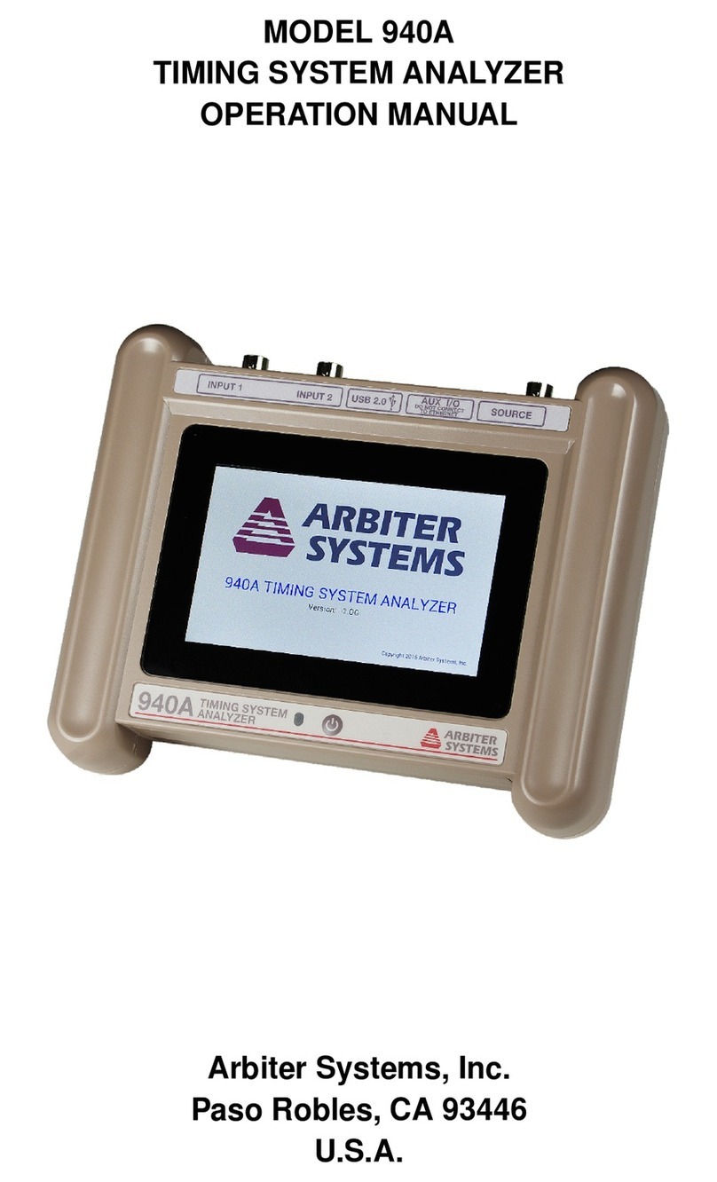
Arbiter Systems
Arbiter Systems 1133A User manual
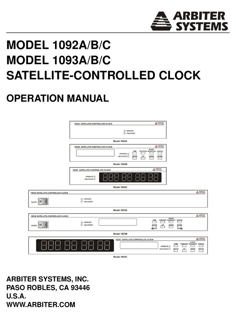
Arbiter Systems
Arbiter Systems 1092A User manual
Arbiter Systems
Arbiter Systems Portable Power Sentinel 933A User manual