Komshine QX55 Series User manual

Preorder
All trademarks and names mentioned in this document belong to Komshine Technologies
Limited(Komshine). The contents of this document are subject to change without notice.
Information from Komshine is supposed to be true and reliable. Komshine will not take
any responsibility for the errors contained in this document or the accidental or secondary
losses caused by the supply and use of this document or the practicality of the version of
the document.
Safety instructions
When using the product, you must pay attention to the following safety measures. Failure
to adopt these safe operation methods or follow the specific warnings described elsewhere
in this manual will violate the safety standards of product design, manufacture and use.
Our company will not take any responsibility for the consequences caused by customers'
violation of these requirements.
1. Working environment
The maximum relative humidity is 95% and the ambient temperature is -10~50℃.
Before turning on the power supply, make sure that the product is set to the matching
power supply voltage, that appropriate insurance is installed, and that all safety measures
are taken.
2. Do not operate in an explosive environment.
Do not use this product in the presence of flammable gas or smoke.
3. Do not remove the protective jacket of the instrument.
User must not remove the instrument cover or replace the internal components. If neces-
sary, please contact our maintenance personnel.
01
enabling today,inspiring tomorrow

Safety terms in this manual
Warning items
02
enabling today,inspiring tomorrow
A warning symbol indicates danger. It prompts the user to pay
attention to a certain process, an operation method or the like.
Failure to operate correctly or follow the rules may cause per-
sonal injury. Do not proceed to the next step until you fully
understand and meet the pointed warning conditions.
A caution symbol indicates danger. It draws the user's attention
to a certain process, this operation method or the like. If you
can't operate correctly or follow the rules, the instrument may
be partially or completely damaged or destroyed. Don't continue
to the next step until you understand and meet the pointed cau-
tion conditions safely.
The symbol gives information that is helpful for the use and
maintenance of the instrument.
Optical Time-Domain Reflectometer (OTDR) is a laser device, so users should
always avoid looking directly at the laser output port. Users can't observe the
output port of the light source with a microscope, magnifying glass and other
equipment. The energy of the laser beam gathers on the retina, which will
cause permanent damage to the eyes.
●When measuring optical fiber with OTDR, there must be no working light in
the measured optical fiber (except PON function). Otherwise, the measure-
ment results will be inaccurate.
●When measuring optical fiber with OTDR, the optical interface must ensure
good contact. Otherwise, the measurement results will be inaccurate.

Matters that need attention
03
enabling today,inspiring tomorrow
Battery:
The power supply battery of OTDR of Komshine is rechargeable li-polymer. If you
don't use the instrument for a long time, please charge the battery before using it. If
the instrument is idle for more than 2 months, you should charge it in time to keep the
battery power. Do not charge the battery for more than 8 hours; Do not remove the
battery without permission; Please keep the battery away from the fire source and
strong heat; Do not open or damage the battery; Do not touch the electrolyte of the
battery, so as not to hurt your eyes and corrode your skin and clothes.
External power supply:
OTDR supports external power supply, and the power supply requirement is
DC12V/2.5A
Attention to laser radiation:
During the measurement of the optical fiber system, attention should be paid to avoid
the eyes facing the open-circuit optical fiber, optical fiber interface, optical fiber con-
nection point and other light sources, or the eyes will contact the transmitting laser
and be hurt.
1. When the optical time domain reflectometer works, don't look directly at the laser
output port;
2. After using the optical time domain reflectometer, please cover the dust cap of the
optical port;
3. Do not look directly at the unconnected end of the optical fiber under test. If possi-
ble, point the unconnected end of the optical fiber to a non-reflective object.

Content
Preorder.....................................................................................................
Safety instruction..........................................................................................
Safety terms in this manual.............................................................................
Warning items...............................................................................................
Matters need attention....................................................................................
I. Overview.................................................................................................
1. Contents of this manual..............................................................................
2. Unpacking inspection of products ..............................................................
3. Product introduction..................................................................................
4. Principle introduction.................................................................................
5. Features of this product..............................................................................
II. the basic operation...............................................................................
1. Description of instrument function interface.................................................
2. Description of instrument keys...................................................................
3. Battery and charging.................................................................................
4. Operate VFL function ............................................................................
5. Operate OPM function...............................................................................
6. Operate SLS function................................................................................
7. Operate FIP function.................................................................................
8. Operate RJ45 functions.............................................................................
9. Document management.............................................................................
10. System settings........................................................................................
04
1
1
2
2
3
6
6
6
7
8
12
13
16
16
17
18
18
19
21
25
6
12
enabling today,inspiring tomorrow

III. Introduction of OTDR functions........................................................
1. Test information of curve interface............................................................
2. Link map page........................................................................................
3. Setup page.............................................................................................
4. Wavelength switching..............................................................................
5. PON function introduction.......................................................................
Enclosure..................................................................................................
A. Event type description ...........................................................................
B. Maintenance and calibration instructions...................................................
C. Warranty terms......................................................................................
D. Technical index information of OTDR......................................................
05
32
63
63
68
69
71
33
40
41
61
61
enabling today,inspiring tomorrow

06
I. Overview
enabling today,inspiring tomorrow
1. Contents of this manual
First of all, thank you for choosing our products. Please read this manual carefully before
using it, especially the warning and attention information, so as to avoid injury to your
body or instrument due to wrong operation.This manual mainly contains the common oper-
ation and maintenance information of the instrument, as well as troubleshooting guide and
various information about obtaining technology and service.All the instruments have gone
through strict inspection and quality control process before leaving the factory.
2. Unpacking inspection of products
This product is packed and consigned according to the standard assembly and shipping
procedures. When receiving the instrument, please check the product list according to the
packing list and check the appearance quality of the product, and find out the possible
physical damage of the product in the process of shipping.In case of packaging damage,
please keep the original packaging materials and immediately inform the freight company
and the supplier agent of the product to solve the problem properly.In the product packag-
ing, along with the instrument, there should also be some attached articles and related man-
uals. Please refer to the packing list for details. If you find that the materials in the box are
not complete, please contact the agent responsible for your supply to solve the problem. If
necessary, you can also contact us directly by email.
3. Product introduction
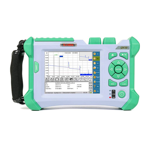
Our OTDR is a reliable instrument for measuring optical fiber characteristics.This series
of products are small, light and easy to operate. It adopts ergonomic shape design and
high-definition LCD screen, and has a data storage function. These data can be analyzed
by PC software, and the optical fiber transmission quality can be analyzed, and the
post-processing, archiving and printing of measurement results can be realized.In particu-
lar, you can see the characteristics of the optical fiber link and the distribution of the opti-
cal fiber through the measurement of the optical fiber link and the image characteris-
tics.You can use it to periodically check whether the link meets the specifications.In order

Pulse generator E/O
O/E
Enlarge
signal
processing
Master clock monitor
Optical directional
coupler
Connector Optical fiber
07
enabling today,inspiring tomorrow
to record the optical fiber transmission quality, it is necessary to measure the optical path,
total loss, loss of all joints and connectors.By looking at the "event points" in the optical
fiber, the installation and maintenance personnel point out these irregularities in the optical
fiber, locate their positions, and measure the attenuation between them, as well as the
resulting loss and attenuation uniformity.In a word, OTDR is a necessary tool for the pro-
duction, installation and maintenance of optical fiber and optical cable.
4. Principle introduction
OTDR uses its laser light source to send a beam of optical pulse to the measured optical
fiber. The optical signal reflected back to the OTDR will be reflected on the optical fiber
itself and each characteristic point. The reflected optical signal is coupled to the OTDR
receiver through directional coupling, and converted into an electrical signal here. Then,
through a series of signal processing means, the situation of the whole optical fiber link is
displayed.As shown in the figure below:

5. Features of the product:
1) Basic functions of OTDR:
a.Measure the length of optical cable and optical fiber;
b.Determine the location of optical cable and optical fiber fault point and breakpoint;
c.Describe the loss distribution curve of optical cable and optical fiber;
d.The attenuation coefficient of optical cable and optical fiber is measured;
e.Measure the loss between optical cable and optical fiber;
f.Measure the insertion loss of optical cable and optical fiber connector;
g.Measure the reflection intensity of optical fiber and optical fiber reflection events;
h.The link map shows the status of the fiber link.
08
enabling today,inspiring tomorrow
Trace Display Window_Menu List
open files
OTDR Settings
save files
Horizontal magnifying curve
Horizontal narrowing curve
Vertical magnification curve
Vertical narrowing curve
Curve 1:1
Choose the previous event
Choose the next incident
Battery level indicator
Select a function with up and down navigation keys,
press the [ENTER] key to enter the operating interface
Type Distance
(km) Loss
(dB) Ref.
(dB) Att.
(dB/km)
S
1/5
2/5
0.00
2.58
5.01
0.073
3.104
-34.657
-31.349
0.311
0.317
0.303
12 3 54
A: 0km/0.0dB
B:17.5km/0.035
500ns 1550nm 15sAuto-mode
35.00km

b. SLS function: This function supports two kinds of light sources of 1310/1550nm
and multiple modulation modes.
09
enabling today,inspiring tomorrow
No looking at the port !
Hz
CW
1310nm
1000
2) Other incidental functions:
a. VFL function: 650 ± 20nm light source is used for this function, and visual light source is
provided for optical fiber fault location by means of visualization, the visible light source emits
red light visible to human eyes, which can be detected in the blind area of optical fiber test
direct fault (breakpoint) location, and can also be used for core comparison in multi-core opti-
cal cable. Support Two working modes: constant light and 2Hz flashing.

10
enabling today,inspiring tomorrow
c. OPM function: This function is used to measure the power of the light source, and supports
the measurement of optical power of multiple wavelengths.
d. FIP function: This function is used to detect the cutting quality of optical fiber end face and
its cleanliness; Connect the end face tester through USB interface, and support the center am-
plification function.

3) Other features:
●3.5-inch HD display, easy operation with multiple buttons;
●Small size and lightweight;
●Graphical display of trace data, easy to operate;
●Trace storage function;
●USB interface;
●Humanized upper computer software, which edits, backs up and archives the measurement
data;
●External power input: input voltage 12V, input current ≤ 2.5A; Battery powered.
11
enabling today,inspiring tomorrow
Result:Test complete!
Number EIA/TIA568A Number
2
3
4
5
6
7
8
--
--
--
--
--
--
--
--
Common Search
2021.07.20
OTDR VFL OPM
FIP FileRJ45
LightSource
Set
Sequence Search
e. Flashlight function: This function provides a guarantee for the normal use of the instrument
under the condition of insufficient lighting conditions;
f. RJ45 function: This function is divided into two functions: line searching and line alignment.
The alignment is to test whether the line sequence of the network cable is correct and whether
it is accessible; The line search function is to find the target network cable among multiple net-
work cables.

1. Description of instrument function interface
12
II. The basic operation
enabling today,inspiring tomorrow
OPM port
Charging
port
Charging
indicator
USB
RJ45
VFL port
This chapter introduces the basic operation methods of the instrument, mainly including the
description of the instrument keys and the use of common interfaces of the instrument. If you
have any questions during the use, please contact the technical support staff of Komshine or our
agent.
1) OTDR optical interface: SC/UPC optical connector is used, and the connector of FC/UPC or
ST/UPC can be replaced; At the same time, the interface can also be used for the interface of
light source function;
2) OPM interface: 2.5mm universal interface (When it’s QX55-P model, it’s SM-LIVE port);
3) VFL interface: 2.5mm universal interface;
4) Power source: Adapter requirements: 12V, 2.5A;
5) Data transmission interface: USB 2.0 interface, can be used to export the data stored in the
machine, can also be connected to the optical fiber end detector for fiber end detection;
6) Network interface: RJ45 standard interface, including 1 host and 1 remote external interface;
It is mainly to carry out network line to line and find network cable.
OTDR
(SM-LIVE)
QX55-S port ▲QX55-P port ▲
OTDR(SM)
/OLS port
LED

When testing optical fiber with dual wavelength, two curves will appear on the main interface
of OTDR. At this time, the switching curve is carried out through , as shown in the
figure below. The image before and after waveform switching is shown.The red curve is the
current curve, and the grey curve is the curve to be analyzed.
2. Description of instrument keys
Switch curve interface and
link diagram interface
Switch wavelength at
dual wavelength
A / B benchmarking key
ENTER key
Power on key
File management
OTDR Test
Direction key
ESC key
VFL
1)Enter the key
13
enabling today,inspiring tomorrow

2) Enter key
3) Power on key
4) File management
5) A/B benchmarking key
14
enabling today,inspiring tomorrow
ENTER
A B
B: 24.094
Type Distance
(km) Loss
(dB) Ref.
(dB) Att.
(dB/km)
S
1
2
0.00
217.70
327.97
-38.480
-41.709
-50.788
0.464
0.335
0.327
12 3 54
A: 0km/0.0dB
B:17.5km/0.035
50ns 1310nm 15sAuto-mode1000.00m
0.289
0.783
It is used to change the setting parameters, select the content of interest, and enable the corre-
sponding functions.
The power on key has two functions. Long press the button to realize the function of switch on
and off;Press the button briefly to turn the flashlight on or off.Among them, the flashlight func-
tion can be turned on and off in each interface.
The file management button can be realized in the main interface of the instrument. One key
can enter the file management interface, and there is no need to control the direction key to
enter the file management interface.
In OTDR interface, it is used to switch a / b marking lines;When the marker line is active, the
color is green, and the inactive state is gray;As shown in the figure below:

6) Switch button
7) Start/ stop test
8) Direction key
9) ESC key
15
10) Red light source switch key
enabling today,inspiring tomorrow
ENTER
In OTDR interface, the key is used to switch between link map and test curve;When the current
display is the test curve, press this button to display the link map; when the current display is
the link map, press this button to display the test curve.
This key is used to control the OTDR test;In particular, the OTDR test function can be realized
by controlling the button in the OTDR setting interface.If you want to stop the test during the
retest, press this button as well.
The key is mainly used for various menus in navigation instrument;Under the test curve of
OTDR interface, the left and right buttons become the control keys of a / b benchmark;Under
the link map of the OTDR interface, the left and right buttons become the control keys of the
event map icon, that is, by controlling the left and right buttons, the events in the event list can
be switched.
When operating the instrument, this button is used to cancel the current operation or return to
the previous menu.In particular, long press the button to capture the interface of the current
instrument and save it in the instrument.
In addition to OTDR interface and stable light source interface, one-click access to red light
source interface can be realized.

1) Electric quantity display
When the machine is turned on, we can see the battery information in the upper right corner of
the machine:
The battery power is ≤5%, which is in a very low state. If the battery is not charged, it
will be turned off soon;
The battery power is < 20%, which is in a low power state;
Battery capacity < 50%;
The battery capacity is less than or equal to 85%, and the battery capacity is sufficient,
so the instrument can be subjected to optical fiber measurement, software upgrade and other
operations;
Battery capacity > 85%;
Battery charging status.
3. Battery charging
16
enabling today,inspiring tomorrow
2) Battery charging:
When charging the battery, charge it quickly, and then charge it slowly with trickle when the
voltage reaches the predetermined value. Generally, the charging temperature of the battery is:
0~+45℃, which is suitable for indoor use. Exceeding the temperature range during charging
will lead to unsatisfactory charging or battery damage, which will affect the battery life. The
charging time of this battery is ≤4 hours; Do not charge the battery for more than 6 hours to pre-
vent damage to the battery.

No looking at the port !
-54.88 dBm
1310 nm
λ:
REF: 0.00 dB
nW
5.6
17
enabling today,inspiring tomorrow
Turn on--CW
PW
Turn off
Switch wavelength
Switch unit
Set the current power
valueas the reference value
Set the reference 0
4. Operating VFL function:
This function is easy to use. Control the "up and down" direction keys, hold the cursor at the
corresponding position, and then select the mode you want to set according to the prompt infor-
mation in the following figure. As shown in the figure below:
5. Operating OPM functions:
1)According to the frequency of the measured light source, press enter to switch the wave-
length; Be sure to keep the measured wavelength consistent with the set wavelength, otherwise,
the test results will be inaccurate;
2)According to the user's requirements, the unit of power of the tested light source can be
selected; Note that when the unit is dB, the displayed result is relative to the reference value;
3)Set the reference value or set the reference value to 0, which is convenient for users to view
the test results.

No looking at the port !
Hz
CW:
1310nm
1000
18
enabling today,inspiring tomorrow
6. Operating SLS function:
The stable light source (SLS)function and OTDR function share one port. The SLS function
supports stable light sources with 1310 and 1550 wavelengths, and the output power is above
-10dBm. As shown in the figure below, note that wavelength switching and frequency switching
can only be operated when the light source function is turned on; When the light source function
is turned on, you can't look directly at the interface to prevent eye injury. The modulation
frequencies supported by this function are 1kHz and 2kHz, where CW mode refers to continuous
light-emitting mode.
7. Operating FIP function:
This function is a function of detecting the quality of optical fiber end face; Connect with our
external products and end face tester through USB port; As shown in the figure below:
ON
Switch wavelength
Switch HZ
OFF
Open the file
Save
Middle

19
enabling today,inspiring tomorrow
Result:Test complete!
Number EIA/TIA568A Number
2
3
4
5
6
7
8
--
--
--
--
--
--
--
--
Among them, the open file button displays the saved optical fiber end face picture;
Saving refers to saving the picture of the optical fiber end face currently being tested;
Centering refers to placing the fiber end face in the center of the display area.
8. Operating RJ45 functions:
This function is mainly to carry out network line alignment and find network lines.
1)Network cable sequencing function: This function is used to test the network cable sequence,
as shown in the following figure:
First, select the category of network cable, and use Class A or Class B standard;
Secondly, one end of the network cable is connected to the network port of the instrument, and
the other end is connected to the external network port;
Third, select the Start button and press the enter key to test;
Finally, if the network cable sequence is completely normal, the display result is as shown in the
above figure, and the numbers in the right column are exactly the same as those in the left
column; If there is a problem with the sequence of a network cable, the word "-1" will appear in
the corresponding line, as shown in the following figure:
This manual suits for next models
2
Table of contents
Other Komshine Measuring Instrument manuals

Komshine
Komshine KLS-35m User manual

Komshine
Komshine KLS-35 User manual

Komshine
Komshine KFL-11M User manual

Komshine
Komshine KPM-35m User manual

Komshine
Komshine KLS-25m User manual

Komshine
Komshine KPM-35 User manual

Komshine
Komshine KPV-53 User manual

Komshine
Komshine KPN-35 PON User manual

Komshine
Komshine KLS-35 User manual
Komshine
Komshine KPM-25m User manual