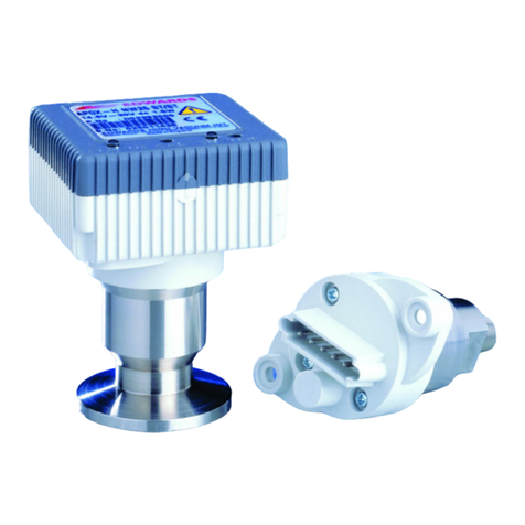
Edwards PRG20K User manual

edwardsvacuum.com
PRG20K AND PRG20KCR PASSIVE
PIRANI GAUGE
INSTRUCTION MANUAL
Publication number: D0300020001EN
Issue: A
Original Instructions

This product has been manufactured under a quality management system certified to ISO 9001:2008
07.06.2017, Eastbourne
Declaration of Conformity
We, Edwards,
Innovation Drive,
Burgess Hill,
West Sussex,
RH15 9TW, UK
declare under our sole responsibility, as manufacturer and person within the EU authorised
to assemble the technical file, that the product(s)
•Pirani (PRG) gauges connected to controllers (PGC).
D03000200
PRG20K – NW16 AI
D03000210
PRG20K – DN16CF SS
D03000220
PRG20KCR – NW16 SS
D03000400
PGC201 Pirani/Penning Contr +*
D03000410
PGC202 Pirani/Ion Contr +*
D03000201
PRG cable 5 m
D03000202
PRG cable 10 m
D03000203
PRG cable 20 m
D03000204
PRG cable 30 m
D03000205
PRG cable 50 m
to which this declaration relates is in conformity with the following standard(s) or other
normative document(s)
EN61010-1:2010 Safety Requirements for Electrical Equipment for Measurement,
Control and Laboratory Use. General Requirements
EN61326-1:2013 Class B,
Industrial Electrical equipment for measurement, control and laboratory
Use. EMC requirements. General requirements
and fulfils all the relevant provisions of
(+) 2014/35/EU Low Voltage Directive
(*) 2014/30/EU Electromagnetic Compatibility (EMC) Directive
2011/65/EU Restriction of Certain Hazardous Substances (RoHS) Directive
2012/19/EU Waste from Electrical and Electronic Equipment (WEEE) Directive
Note: This declaration covers all product serial numbers from the date this Declaration was
signed onwards.
Larry Marini, Senior Technical
Date and Place
P200-10-168 Issue A

This page intentionally blank.

Copyright notice
© Edwards Limited 2017. All rights reserved.
Trademark credits
Edwards and the Edwards logo are trademarks of Edwards Limited.
D0300020001EN - Copyright notice
Page 2

D0300020001EN - Contents
Page i
Contents
Safety 1
Symbols used .................................................................................................................... 1
Symbols for residual risks ........................................................................................... 1
Personnel qualifications ................................................................................................... 1
General safety instructions ............................................................................................... 1
Responsibility and warranty ............................................................................................. 2
Description 3
Product identification ....................................................................................................... 3
Validity .............................................................................................................................. 3
Intended use ..................................................................................................................... 3
Unpacking and Checking ................................................................................................... 4
Scope of delivery .............................................................................................................. 4
Technical data 5
PRG20K gauge head NW16 ............................................................................................... 5
PRG20K gauge head DN16CF ............................................................................................ 5
PRG20KCR gauge head NW16 .......................................................................................... 6
Installation 7
Supplied equipment ......................................................................................................... 7
Connection of the gauge head .......................................................................................... 7
Adjustment of the gauge head ......................................................................................... 8
Adjustment of the gauge head in connection with operating units
PGC201 and PGC202 ........................................................................................................ 8
Maintenance 9
Exchanging the sensing cell .............................................................................................. 9
Spare parts and accessories 11
Spares ............................................................................................................................. 11
Accessories ..................................................................................................................... 11
Storing and waste disposal 12
Storage ............................................................................................................................ 12
Disposal ........................................................................................................................... 12
Returning the product 13
Disposal 14
Separating the components ........................................................................................... 14
Contaminated components ............................................................................................ 14
Other components .......................................................................................................... 14
cg/03/17

D0300020001EN - Contents
Page ii
List of Figures
Dimensions ................................................................................................................ 6
Gauge head PRG20K - NW16 Al / PRG20K - DN16CF SS /
PRG20KCR - NW16 SS ................................................................................................ 8
Disassembled PRG20K - NW16 Al / PRG20K - DN16CF SS /
PRG20KCR - NW16 SS gauge head .......................................................................... 10

D0300020001EN - Safety
Page 1
Safety
Symbols used
Symbols for residual risks
Personnel qualifications
All work described in this document may only be carried out by persons who have suitable
technical training and the necessary experience or who have been instructed.
General safety instructions
Adhere to the applicable regulations and take the necessary precautions for the
process media used.
Consider possible reactions with the product materials.
Consider possible reactions (for example, explosion) of the process media due to the
heat generated by the product.
Adhere to the applicable regulations and take the necessary precautions for all work
to be performed and consider the safety instructions in this document.
Ensure that all vacuum components have not been contaminated before beginning
any work. If so, adhere to the relevant regulations and take the necessary precautions
when handling contaminated parts.
The PRG heads must only be operated with Edwards PGC201 or PGC202 vacuum gauge
controller instruments.
Communicate the safety instructions to all other users.
WARNING:
Warnings are given where failure to observe the instruction could result in injury or death
to people.
CAUTION:
Cautions are given where failure to observe the instruction could result in damage to the
equipment, associated equipment and process.
Note:
Information on correct handling or use. Disregard can lead to malfunctions or minor
equipment damage.

D0300020001EN - Safety
Page 2
Responsibility and warranty
Edwards will not assume any responsibility or warranty in cases where the operator or third
persons:
Do not observe the information given in this document.
Do not use the product as intended.
Modify the product in any way (conversions, repair work, etc.).
Operate the product with accessories not listed in the corresponding product
documentation.
Subject to technical alterations without prior notice. The figures are not binding.

D0300020001EN - Description
Page 3
Description
The PRG are vacuum gauge heads.
The actual pressure sensing element within the gauge head PRG20K - NW16 is a tungsten
filament.
The PRG gauge heads PRG20K - DN16CF and PRG20KCR - NW16 are made of stainless steel
with a welded ceramics feed-through. The sensing element within the PRG20K - NW16 is a
tungsten filament, whereas the PRG20KCR - NW16 uses a platinum filament.
The gauge heads are supplied fully aligned. Any alignment or recalibration will, if at all
necessary, be required only after a longer period of operation.
The gauge heads are temperature compensated for the range from 0 °C to 40 °C.
The measurement cells can be easily exchanged should this be required. After an exchange
of the sensing cell a recalibration is required by adjusting two potentiometers within in the
gauge head.
Product identification
In all communications with Edwards, please specify the information on the product
nameplate.
Validity
This document applies to products with part numbers
The part number (No:) can be taken from the product nameplate.
Intended use
The PRG gauge heads are vacuum gauge heads which are operated in connection with the
operating units PGC201 and PGC202.
The gauge head is used for the measurement of absolute pressures in the rough and fine
vacuum range in accordance with the technical data.
Product Description Item number
PRG20K NW16 AL D03000200
PRG20K DN16CF SS D03000210
PRG20KCR NW16 SS D03000220
PRG cable 5m D03000201
PRG cable 10m D03000202
PRG cable 20m D03000203
PRG cable 30m D03000204
PRG cable 50m D03000205

D0300020001EN - Description
Page 4
Unpacking and Checking
Unpack the PRG gauge head immediately after delivery, even if it is to be installed at a later
date.
Retain the packaging materials in the event of complaints about damage.
Carefully examine the visually. If any damage is discovered, report it immediately to the
forwarding agent and insurer. If the gauge head has to be replaced, contact the orders
department.
Scope of delivery
PRG gauge head
Securing bow for connection plug

D0300020001EN - Technical data
Page 5
Technical data
PRG20K gauge head NW16
PRG20K gauge head DN16CF
Measurement range 0.5 x 10⁻⁴ to 1 x 10³mbar
Filament temperature 110 °C
Disruption pressure (Burst pressure)
(absolute)
3 bar
Measurement volume 11 cm3
Connection flange NW16
Filament material Tungsten
Material in contact with the medium Aluminium, glass, Vacon, Tungsten, chrome-nickel
8020, steel nickel-plated, Epoxy adhesive
Operating temperature 0 to 40 °C
Maximum ambient temperature 80 °C
Measurement range 0.5 x 10⁻⁴ to 1 x 10³mbar
Filament temperature 110 °C
Disruption pressure (Burst pressure)
(absolute)
10 bar
Measurement volume 10 cm3
Connection flange DN 16 CF
Filament material Tungsten
Material in contact with the medium Stainless steel 1.4301, Tungsten, chrome nickel
8020, ceramics Al2O3, NiFe 42
Operating temperature 0 to 40 °C
Maximum ambient temperature 80 °C

D0300020001EN - Technical data
Page 6
PRG20KCR gauge head NW16
Figure 1 Dimensions
Measurement range 0.5 x 10⁻⁴ to 1 x 10³mbar
Filament temperature 110 °C
Disruption pressure (Burst pressure)
(absolute)
10 bar
Measurement volume 10 cm3
Connection flange NW16
Filament material Platinum
Material in contact with the medium Stainless steel 1.4301, Platinum, chrome nickel
8020, ceramics Al2O3, NiFe 42
Operating temperature 0 to 40 °C
Max. ambient temperature 80 °C

D0300020001EN - Installation
Page 7
Installation
Supplied equipment
PRG gauge head
Securing clip for connector
Operating instructions
Connection of the gauge head
Install the gauge head vertically, i.e. with the flange facing downwards. Dimensional drawing
see Figure 1. The dimensions given with a double asterisk (**) to the PRG20K - DN16CF and
PRG20KCR - NW16 gauge head. Otherwise the dimensions are the same for both gauge
heads.
The maximum permissible ambient temperature for the gauge head is 80 °C. However, at this
temperature the accuracy specified for the gauge head is no longer ensured, as the
temperature compensation is only effective up to 40 °C.
If the gauge head is subjected to strong thermal radiation, it has to be protected by a suitable
thermal screen. In the case that heat is transferred to the gauge head via the connection
cable, a section of the connection cable may be cooled by a cooling spiral.
Any contamination of the sensing cell will impair the accuracy of the pressure readings
obtained. Special care must be taken in the presence of substances which cannot be removed
by solvents.
Suitable orifice plates or bends may be employed to keep any possible sources of
contamination away from the gauge head.
Bent lines should be laid in such a way that no condensate can collect or the vacuum line
cannot become blocked.
The gauge heads are connected to the operating unit via standard gauge head cables.
For the purpose of improved resistance to interference the gauge heads have been equipped
with an additional ground connection (screw terminal) at the housing which is directly linked
to the metal housing of the sensing cell.
Standard gauge head cables are fitted with a ring terminal at each end of the cable. The ring
terminals should be connected to the ground connection (screw terminal) at the housing of
WARNING:
Do not use the PRG for safety critical applications. The PRG is not intended to be fail safe.
WARNING:
Do not use the PRG to measure the pressure of explosive of flammable gasses or mixtures.
The gauge contains a heated filament which can operate at extremely high temperatures
under fault conditions.
Note:
Do not install a vent valve in the immediate vicinity of the gauge head. Sudden changes in air
flow may result in mechanical damage to the filament.

D0300020001EN - Installation
Page 8
the gauge head and the protective earth conductor screw on the rear of the PGC201/PGC202
controller.
Ensure that the correct filament material is selected on the PGC201/PGC202 controller. Refer
to the operating instructions for the PGC201/PGC202 controller.
Ensure the correct filament material is selected (tungsten or platinum) when operating the
gauge head in connection with an operating unit PGC201 and PGC202 (see Operating
Instructions PGC201 and PGC202).
The connecting plug can be safely attached to the gauge via the securing clip. To do so, push
the clip over the connecting pug and let them snap in the provided holes which are in the
shell.
Adjustment of the gauge head
Adjustment is performed as follows:
Remove the caps covering the potentiometers on the gauge head.
Vent vacuum system and set 100% potentiometer (Figure 2 item 1) so that the
controller indicates full scale (atmospheric pressure).
Pump down vacuum system to a pressure below 5 x 10⁻⁴ mbar and set "0"
potentiometer (Figure 2 item 2) so that the controller indicates 0.
Vent vacuum system and recheck the 100% adjustment. Correct deviation, if any, by
means of potentiometer.
If a correction of the 100% adjustment was necessary the zero adjustment must be
repeated in any case.
After having completed the adjustment fit the caps to cover the potentiometers.
Figure 2 Gauge head PRG20K - NW16 Al / PRG20K - DN16CF SS / PRG20KCR - NW16 SS
Adjustment of the gauge head in connection with operating units
PGC201 and PGC202
Refer to the operating instructions supplied with the PGC201 or PGC202.
Note:
The ground wire may only be connected if potential equalization between the flange of the
vacuum apparatus and the operating unit is ensured. If necessary install the gauge head so
that it is electrically isolated from the vacuum apparatus.
1 100% potentiometer
2 0% potentiometer

D0300020001EN - Maintenance
Page 9
Maintenance
Exchanging the sensing cell
All items in this section refer to Figure 3.
One half of the housing (item 1) is fitted with plastic catches (item 2) which must properly
engage in the slots (item 8) provided in the other half of the housing (item 7) so as to firmly
connect the two halves of the housing (item 1) and (item 7).
Apply a screwdriver to the upper slit on the longer front so as to disengage the plastic catch
(item 2) by pushing it backwards. Simultaneously, pull both halves of the shell (item 1) and
(item 7) apart.
Next apply a screwdriver to the lower slit on the longer front so as to disengage the plastic
catch by pushing it backwards. Simultaneously, pull both halves of the shell apart.
Repeat this for the shorter front.
Detach shell (item 1).
Remove the contact spring (item 4) by loosening the fixing screw (item 3).
Remove the sensing cell (item 11) together with the PCB. and plug (item 6) from the
remaining shell.
Carefully separate the sensing cell (item 11) from the PCB (item 6).
Remove the insulating plate (item 5) from the measurement cell.
Exchange the sensing cell.
Insert insulating plate (item 5) between PCB and measurement cell.
WARNING:
Contaminated parts can be detrimental to health and environment.
Before beginning work, find out whether any parts are contaminated. Adhere to the
relevant regulations and take the necessary precautions when handling contaminated
parts.
CAUTION:
Dirt and damage can impair the function of the vacuum component.
When handling vacuum components, take appropriate measures to ensure cleanliness
and prevent damage.
CAUTION:
Touching the product with bare hands increases the desorption rate.
Always wear clean, lint-free gloves and use clean tools when working in this area.
Note:
The cell can be mounted on the PCB in either orientation.

D0300020001EN - Maintenance
Page 10
During assembly of the gauge head make sure that the holder (item 10) has been placed in
the housing shell and that the temperature sensor is pressed against the sensing cell.
The gauge head is reassembled in the reverse order.
Figure 3 Disassembled PRG20K - NW16 Al / PRG20K - DN16CF SS / PRG20KCR - NW16 SS gauge head
1 One half of the housing with plastic catches
2 Plastic catch
3 Plastic catch
4 Contact spring
5 Insulating plate
6 PCB complete
7 One half of the housing with slots
8 Slots for opening the housing
9 Cap
10 Holder
11 Sensing cell

D0300020001EN - Spare parts and accessories
Page 11
Spare parts and accessories
Spares
When ordering spare parts, always indicate:
All information on the product nameplate.
Description and ordering number according to the spare parts list.
Accessories
Product description Item number
Replacement sensing cell K D03000209
Replacement sensing cell KCR D03000229
Product description Item number
PRG Cable 5m D03000201
PRG Cable 10m D03000202
PRG Cable 20m D03000203
PRG Cable 30m D03000204
PRG Cable 50m D03000205

D0300020001EN - Storing and waste disposal
Page 12
Storing and waste disposal
Storage
Disposal
Dispose of the PRG and any components safely and in accordance with all local and national
safety and environmental requirements.
Alternatively, the PRG and /or cables may be able to be recycled; contact Edwards or supplier
for advice (also see below).
The PRG and associated cables are within the scope of the European Directive on Waste and
Electronic Equipment, 2012/19/EU. Edwards offers customers a recycling service for the
product/cables/associated gauge heads at the end of the product's life. Contact Edwards for
advice on how to return the PRG and/or cables for recycling
CAUTION:
Cover the vacuum ports of the product with protective caps or grease free aluminium foil.
Do not exceed the admissible storage temperature range.
Inappropriate storage leads to an increase in the desorption rate and/or may result in
mechanical damage of the product.

D0300020001EN - Returning the product
Page 13
Returning the product
Products that are not clearly declared as "free of harmful substances" are decontaminated at
the expense of the customer.
Products not accompanied by a duly completed declaration of contamination are returned to
the sender at his own expense.
WARNING:
Products returned to Edwards for service or repair should, if possible, be free of harmful
substances (for example, radioactive, toxic, caustic or microbiological). Otherwise, the
type of contamination must be declared.
Adhere to the forwarding regulations of all involved countries and forwarding companies
and enclose a completed contamination declaration.

D0300020001EN - Disposal
Page 14
Disposal
Separating the components
After disassembling the product, separate its components according to the following criteria:
Contaminated components
Contaminated components (radioactive, toxic, caustic or biological hazard, and so forth) must
be decontaminated in accordance with the relevant national regulations, separated
according to their materials, and disposed of.
Other components
Such components must be separated according to their materials and recycled.
WARNING:
Contaminated parts can be detrimental to health and environment.
Before beginning to work, find out whether any parts are contaminated. Adhere to the
relevant regulations and take the necessary precautions when handling contaminated
parts.
WARNING:
Products returned to Edwards for service or repair should, if possible, be free of harmful
substances (for example, radioactive, toxic, caustic or microbiological). Otherwise, the
type of contamination must be declared.
Adhere to the forwarding regulations of all involved countries and forwarding companies
and enclose a completed contamination declaration.
This manual suits for next models
1
Table of contents
Other Edwards Measuring Instrument manuals
Edwards
Edwards IG40 BA User manual
Edwards
Edwards ATC-E User manual

Edwards
Edwards AIM-S-NW25 User manual
Edwards
Edwards FSRZI-A Assembly instructions
Edwards
Edwards APG100 User manual
Edwards
Edwards AIM-S-NW25 User manual

Edwards
Edwards AIM-S-NW25 User manual
Edwards
Edwards GXS 0-60 SLM User manual
Edwards
Edwards OLM100 User manual
Edwards
Edwards AIM-SI1-NW25 User manual
