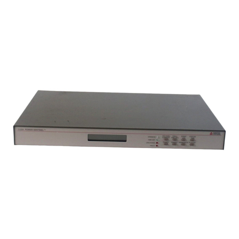
Arbiter Systems Portable Power Sentinel 933A User manual

Model 933A
Portable Power Sentinel™
Operation Manual
DISPLAYDISPLAY SETUPSETUP
REVIEWREVIEW PRINTPRINT
LOGLOG HOLDHOLD
778899
445566
112233
00..
A
933A – 20Arms DIRECT INPUT CURRENT MODULE
A B C
20 Arms MAXIMUM
Model 933A
TM
Portable Power Sentinel
Model 933A
TM
Portable Power Sentinel
TIMING SOURCE
COMMUNICATION
AUXILIARY I/O
VOLTAGE GROUND
A B C N
650Vrms Max.
TM
933A PORTABLE POWER SENTINEL
110–250Vdc
85–264Vac 47–440Hz
FUSE 1AF/250
IRIG–B IEEE 1344
GPS RECEIVER
USB 1.0
RS-232
SAFETY
Arbiter Systems, Inc.
Paso Robles, CA 93446
U.S.A.
www.arbiter.com

Description
This manual is issued for reference only, at the convenience of Arbiter
Systems. Reasonable effort was made to verify that all contents were
accurate as of the time of publication. Check with Arbiter Systems at the
address below for any revisions made since the original date of publication.
Contact Information
Arbiter Systems, Inc.
1324 Vendels Circle, Suite 121
Paso Robles, CA 93446
(805) 237-3831
Website: www.arbiter.com
mailto: techsupp[email protected]
mailto: [email protected]
Definition
This manual describes the Model 933A Portable Power Sentinel, Synchro-
nized Power Quality Meter and PSCSV
software.
Firmware and Firmware Updates
This manual was created based on version 1.12 of the main DSP program,
dated 18 February 2010. To display the firmware date, press DISPLAY >
9-Config & Status >the Version & S/N soft key.
Firmware Updates are available from Arbiter Systems website or by
contacting technical support at the information above.
ii

LIMITED WARRANTY
Arbiter Systems makes no warranty, expressed or implied, on any product
manufactured or sold by Arbiter Systems except for the following limited
warranty against defects in materials and workmanship on products
manufactured by Arbiter Systems.
Products manufactured by Arbiter Systems are guaranteed against defec-
tive materials and workmanship under normal use and service for one year
from the date of delivery. The responsibility of Arbiter Systems under this
warranty is limited to repair or replacement, at Arbiter Systems’ option, of
any product found to be defective. Arbiter Systems shall have no liability
under this warranty unless it receives written notice of any claimed defect,
within the earlier of:
Thirty days of discovery by Buyer, or;
One year from the date of delivery.
For warranty service or repair, products must be returned to a service
facility designated by Arbiter Systems. Buyer shall prepay all shipping
charges to Arbiter Systems, and Arbiter Systems shall pay shipping charges
incurred in returning the product to Buyer. However, Buyer shall pay all
shipping charges, duties and taxes for products returned to Buyer in a
country other than the United States of America.
THE WARRANTY SET FORTH HEREIN CONSTITUTES THE ONLY
WARRANTY OBLIGATIONS OF ARBITER SYSTEMS, EXPRESSED
OR IMPLIED, STATUTORY, BY OPERATION OF LAW, OR OTH-
ERWISE. ARBITER SYSTEMS DISCLAIMS ANY WARRANTY OF
MERCHANTABILITY OR FITNESS FOR A PARTICULAR PURPOSE,
AND BUYER EXPRESSLY WAIVES ALL OTHER WARRANTIES.
This limited warranty does not extend to any product, which has been
subject to
I Improper use or application, abuse, or operation beyond its rated
capacity, or contrary to the instructions in the operation and mainte-
nance manuals (if any);
II Accident;
III Repair or maintenance performed by Buyer, except in accordance
with the operation and maintenance manuals, if any, and any special
instructions of Arbiter Systems;
iii

IV Modification without the prior written authorization of Arbiter Sys-
tems (whether by the substitution of non-approved parts or other-
wise).
The remedies provided herein are Buyer’s sole and exclusive remedies. In
no event shall Arbiter Systems be liable for direct, indirect, incidental
or consequential damages (including loss of profits), whether based on
contract, tort, or other legal theory.
FOR THE FASTEST POSSIBLE SERVICE, PLEASE PROCEED AS
FOLLOWS:
1. Notify Arbiter Systems, Inc., specifying the instrument model
number and serial number and giving full details of the difficulty.
Service data or instrument-return authorization will be provided
upon receipt of this information.
2. If instrument return is authorized, forward prepaid to the manufac-
turer. If it is determined that the instrument is not covered by this
warranty, an estimate will be made before the repair work begins, if
requested.
See Contact Information on page ii.
iv

Arbiter Systems, Inc.
Model 933A
Portable Power Sentinel™
Operation Manual
Chapter 1 Introduction
Chapter 2 Basic Operation
Chapter 3 The Setup Menu
Chapter 4 The Display Menu
Chapter 5 Reviewing 933A Data
Chapter 6 PSCSV Basics
Chapter 7 Triggers and Event Recording
Chapter 8 Specifications
Chapter 9 Functional Description
Chapter 10 Connection Diagrams
Appendix A Glossary
Appendix B Uploading New Firmware
Appendix C CE Mark Certification
Copyright
©
Arbiter Systems Incorporated September 2015 All rights
reserved. International copyright secured.
PD0031100H – Reorder number: AS0093900
v

Contents
1 Introducing the Model 933A 1
1.1 Scope .............................. 1
1.2 Included Accessories . . . . . . . . . . . . . . . . . . . . . . 2
1.3 933AFeatures.......................... 3
1.3.1 Features and Accessories . . . . . . . . . . . . . . . . 3
1.4 Available Accessories . . . . . . . . . . . . . . . . . . . . . . 4
1.4.1 Lead Set Information . . . . . . . . . . . . . . . . . 4
1.4.2 Three-Phase Voltage Lead Set, 813AT . . . . . . . . 5
1.4.3 Three-Phase Voltage Lead Set, 813BT . . . . . . . . 5
1.4.4 3-Phase Spade Lug, Current Lead Set, 816AT . . . . 6
1.4.5 3-Phase Spade Lug, Current Lead Set. 916CT . . . 6
1.4.6 Universal Test Plug Current Lead Set, 811AT . . . . 7
1.4.7 Universal Test Plug Current Lead Set, 811CT . . . . 7
1.4.8 Universal Test Plug Current Shunt . . . . . . . . . . 7
1.4.9 Adjustable Bail . . . . . . . . . . . . . . . . . . . . . 8
1.4.10 400 Amp, 20:1 Precision CT . . . . . . . . . . . . . . 8
1.4.11 Clamp-on Current Probes for the 933A . . . . . . . 9
1.4.12 Low Current Modules . . . . . . . . . . . . . . . . . 9
1.4.13 GPS Antenna Module . . . . . . . . . . . . . . . . . 10
1.4.14 Auxiliary I/O Module . . . . . . . . . . . . . . . . . 11
1.5 Safety Information . . . . . . . . . . . . . . . . . . . . . . . 12
1.5.1 Definitions ....................... 12
1.5.2 Terminology . . . . . . . . . . . . . . . . . . . . . . 12
1.5.3 Warnings ........................ 12
2 Basic Operation 14
2.1 Introduction........................... 14
2.2 Powering the Model 933A . . . . . . . . . . . . . . . . . . . 14
2.2.1 Operation with the AC Power Cord . . . . . . . . . 14
2.2.2 Operation with Battery Power . . . . . . . . . . . . 15
vi

2.2.3 Charging the Internal Battery . . . . . . . . . . . . . 15
2.3 Controls and Connections . . . . . . . . . . . . . . . . . . . 16
2.3.1 Inputs and Interface . . . . . . . . . . . . . . . . . . 18
2.3.2 Front Panel Connectors . . . . . . . . . . . . . . . . 18
2.3.3 Chassis Ground . . . . . . . . . . . . . . . . . . . . . 18
2.3.4 Voltage Inputs, 650 Vrms . . . . . . . . . . . . . . . 19
2.3.5 Current Input Module, 20 Arms (933A-01) . . . . . 19
2.3.6 Synchronizing the 933A . . . . . . . . . . . . . . . . 20
2.3.7 GPS Timing Signals . . . . . . . . . . . . . . . . . . 20
2.3.8 IRIG-B Timing Signals . . . . . . . . . . . . . . . . 21
2.3.9 Communication Ports . . . . . . . . . . . . . . . . . 21
2.3.10 Auxiliary I/O Port . . . . . . . . . . . . . . . . . . . 22
2.3.11 IEC-320 Power Inlet Connector . . . . . . . . . . . . 22
2.4 Function Keys & Indicators . . . . . . . . . . . . . . . . . . 23
2.4.1 On/OffKey....................... 23
2.4.2 Display Selection Key . . . . . . . . . . . . . . . . . 23
2.4.3 Setup −Configuring the 933A . . . . . . . . . . . . 24
2.4.4 Five Soft Keys . . . . . . . . . . . . . . . . . . . . . 24
2.4.5 Display Lighting Key . . . . . . . . . . . . . . . . . 25
2.4.6 Cursor Keypad / Enter Key . . . . . . . . . . . . . . 25
2.4.7 Numeric Keypad . . . . . . . . . . . . . . . . . . . . 26
2.4.8 LogKey......................... 26
2.4.9 ReviewKey....................... 26
2.4.10 PrintKey........................ 26
2.4.11 HoldKey ........................ 27
2.4.12 933A Status Indicators . . . . . . . . . . . . . . . . . 27
2.5 PSCSVSoftware ........................ 29
2.5.1 USB or RS-232C . . . . . . . . . . . . . . . . . . . . 29
2.5.2 Connecting ....................... 29
2.5.3 Configuring....................... 30
2.5.4 Downloading Data . . . . . . . . . . . . . . . . . . . 30
2.6 Bitmapped File Downloading . . . . . . . . . . . . . . . . . 30
2.6.1 Tera Term Pro BMP File Transfer . . . . . . . . . . 31
2.6.2 HyperTerminal BMP File Transfer . . . . . . . . . . 32
3 The Setup Menu 33
3.1 SetupKey............................ 33
3.2 InputSetupMenu ....................... 34
3.2.1 Selecting the System Input . . . . . . . . . . . . . . 34
3.3 ClockTimeSet ........................ 36
3.3.1 Internal Real-Time Clock . . . . . . . . . . . . . . . 36
3.3.2 Clock Setup in Free-Running Mode . . . . . . . . . . 37
vii

3.3.3 Clock Setup in Synchronized Mode . . . . . . . . . . 38
3.4 SerialSetup .......................... 39
3.4.1 Setting up the RS-232 port . . . . . . . . . . . . . . 39
3.5 AutologSetup ......................... 40
3.5.1 Logging Data Indication . . . . . . . . . . . . . . . . 41
3.6 CT/PTSetup ......................... 42
3.7 Custom DST Setup . . . . . . . . . . . . . . . . . . . . . . 43
3.8 CurrentSetup ......................... 44
3.9 Using Optional Low Current Modules . . . . . . . . . . . . 45
3.9.1 Installing ........................ 45
3.9.2 Configuring....................... 46
3.10TriggerSetup ......................... 46
4 The Display Menu 47
4.1 Display Selection . . . . . . . . . . . . . . . . . . . . . . . . 47
4.2 Min–MaxSetup......................... 48
4.3 TabularResults ........................ 49
4.4 Harmonic Results . . . . . . . . . . . . . . . . . . . . . . . 50
4.4.1 Graphical Harmonics . . . . . . . . . . . . . . . . . . 50
4.4.2 Tabular Harmonics . . . . . . . . . . . . . . . . . . . 50
4.5 Waveform Display . . . . . . . . . . . . . . . . . . . . . . . 51
4.5.1 Magnify Waveforms . . . . . . . . . . . . . . . . . . 52
4.6 V&ITabulation........................ 52
4.6.1 Show Sequence . . . . . . . . . . . . . . . . . . . . . 53
4.6.2 ShowRatio ....................... 53
4.6.3 Show Impedance . . . . . . . . . . . . . . . . . . . . 53
4.7 PowerTabulation........................ 54
4.7.1 Power Calculations . . . . . . . . . . . . . . . . . . . 54
4.8 PowerQuality ......................... 55
4.8.1 Min–Max ........................ 55
4.8.2 Flicker Information . . . . . . . . . . . . . . . . . . . 56
4.9 Energy Tabulation . . . . . . . . . . . . . . . . . . . . . . . 57
4.10PhasorDisplay ......................... 58
4.11BasicDataList ........................ 59
4.12Config&Status ........................ 60
4.12.1 Status with GPS Synchronization . . . . . . . . . . . 61
5 Reviewing 933A Data 62
5.1 Review Data Selections . . . . . . . . . . . . . . . . . . . . 62
5.1.1 ShowLogData..................... 63
5.1.2 Show User Event Records . . . . . . . . . . . . . . . 63
5.1.3 Show Power Quality Event Records . . . . . . . . . 63
viii

5.1.4 Erase Log Data . . . . . . . . . . . . . . . . . . . . . 63
5.2 Steps to Locate & Review Records . . . . . . . . . . . . . . 63
5.2.1 Locating the Data Logged During an Event . . . . . 63
5.2.2 Locating Event Records . . . . . . . . . . . . . . . . 64
5.2.3 Reviewing Recorded Data (Show Log) . . . . . . . . 64
5.2.4 Review Selections Soft Key . . . . . . . . . . . . . . 66
5.3 Reviewing User Event Records . . . . . . . . . . . . . . . . 67
5.3.1 Interpreting a User Event Record . . . . . . . . . . . 67
5.3.2 Searching for Records . . . . . . . . . . . . . . . . . 68
5.3.3 Viewing Waveform Data at Time of Event . . . . . . 69
5.4 Reviewing Power Quality Event Data . . . . . . . . . . . . 70
5.4.1 Viewing 1-Second Data Records . . . . . . . . . . . 70
5.5 Reviewing Data using PSCSV . . . . . . . . . . . . . . . . . 71
5.5.1 User Event Record Example . . . . . . . . . . . . . . 72
5.5.2 Per Second Data . . . . . . . . . . . . . . . . . . . . 73
5.5.3 Power Quality Event Record Example . . . . . . . . 74
5.5.4 Waveform Data . . . . . . . . . . . . . . . . . . . . . 75
6 PSCSV Basics 77
6.1 Introduction........................... 77
6.1.1 PSCSV Features . . . . . . . . . . . . . . . . . . . . 77
6.1.2 Linking ......................... 77
6.2 Windows, Menus and Toolbars . . . . . . . . . . . . . . . . 78
6.2.1 MainWindow...................... 78
6.2.2 Menu Definitions . . . . . . . . . . . . . . . . . . . . 79
6.2.3 Toolbar and Button Definitions . . . . . . . . . . . . 81
6.2.4 Connecting with the 933A . . . . . . . . . . . . . . . 84
6.2.5 Configuring the 933A . . . . . . . . . . . . . . . . . 85
6.2.6 Configuring Measurement Parameters . . . . . . . . 88
6.2.7 Other Windows . . . . . . . . . . . . . . . . . . . . . 89
6.3 BroadcastData......................... 91
6.3.1 BasicData ....................... 91
6.3.2 EnergyData ...................... 92
6.3.3 Harmonic Data . . . . . . . . . . . . . . . . . . . . . 93
6.3.4 Harmonic Summary Data . . . . . . . . . . . . . . . 94
6.3.5 Waveform Data . . . . . . . . . . . . . . . . . . . . . 95
6.3.6 PhasorData ...................... 96
6.3.7 Lists of Broadcast Values . . . . . . . . . . . . . . . 97
6.4 Data Conversions . . . . . . . . . . . . . . . . . . . . . . . . 98
6.4.1 Exporting COMTRADE Files . . . . . . . . . . . . . 98
6.4.2 Exporting to CSV Format . . . . . . . . . . . . . . . 99
6.4.3 Exporting to PQDIF Format . . . . . . . . . . . . . 100
ix

6.4.4 Save As Snapshot . . . . . . . . . . . . . . . . . . . 100
7 Triggers and Event Recording 101
7.1 Introduction...........................101
7.1.1 Recording Data to 933A Flash Memory . . . . . . . 101
7.1.2 User Triggers . . . . . . . . . . . . . . . . . . . . . . 102
7.1.3 Power Quality Triggers . . . . . . . . . . . . . . . . 102
7.2 Setting a User Trigger . . . . . . . . . . . . . . . . . . . . . 102
7.2.1 NewTrigger.......................102
7.2.2 LoggingTime......................104
7.2.3 Back Soft key . . . . . . . . . . . . . . . . . . . . . . 104
7.2.4 SAVE SETTINGS Soft Key . . . . . . . . . . . . . . 105
7.2.5 User Trigger Parameter Definitions . . . . . . . . . . 105
7.3 Setting a Power Quality Trigger . . . . . . . . . . . . . . . . 106
7.3.1 Setting Up a New Trigger . . . . . . . . . . . . . . . 107
7.3.2 Power Quality Trigger Parameter Definitions . . . . 108
7.4 Event Waveform Capture . . . . . . . . . . . . . . . . . . . 112
7.4.1 Capture Method and Features . . . . . . . . . . . . 112
7.4.2 High Speed Waveform Capture . . . . . . . . . . . . 112
7.4.3 How Much Data do I Record? . . . . . . . . . . . . . 113
7.4.4 Event Capture Example . . . . . . . . . . . . . . . . 113
7.5 Auxiliary I/O Module . . . . . . . . . . . . . . . . . . . . . 115
7.5.1 Auxiliary I/O Module Description . . . . . . . . . . 115
7.5.2 Configuring Event Inputs . . . . . . . . . . . . . . . 115
7.5.3 Configuring Relays . . . . . . . . . . . . . . . . . . . 117
7.5.4 General Relay Setup Procedure . . . . . . . . . . . . 119
7.6 Configuring Triggers with PSCSV . . . . . . . . . . . . . . . 119
7.6.1 User Triggers . . . . . . . . . . . . . . . . . . . . . . 120
7.6.2 Power Quality Triggers . . . . . . . . . . . . . . . . 121
7.6.3 Auxiliary I/O Module . . . . . . . . . . . . . . . . . 121
8 Specifications 122
8.1 Introduction...........................122
8.2 Input Configurations . . . . . . . . . . . . . . . . . . . . . . 122
8.3 Instrument Interface . . . . . . . . . . . . . . . . . . . . . . 123
8.4 Optional Auxiliary I/O Module . . . . . . . . . . . . . . . . 125
8.5 System Control and Monitoring . . . . . . . . . . . . . . . . 125
8.6 Synchronization . . . . . . . . . . . . . . . . . . . . . . . . . 125
8.7 Measurement Specifications . . . . . . . . . . . . . . . . . . 126
8.8 General .............................127
8.9 Power Requirements . . . . . . . . . . . . . . . . . . . . . . 128
x

9 Functional Description 129
9.1 Scope ..............................129
9.2 Overview ............................129
9.3 Clock Synchronization . . . . . . . . . . . . . . . . . . . . . 130
9.4 CurrentInputs .........................130
9.5 VoltageInputs .........................130
9.6 ErrorAnalysis .........................131
9.7 SignalSampling.........................132
9.8 PowerandEnergy .......................132
9.9 Voltage and Current . . . . . . . . . . . . . . . . . . . . . . 133
9.10 CT and PT Compensation . . . . . . . . . . . . . . . . . . . 133
9.11 Transformer Compensation . . . . . . . . . . . . . . . . . . 134
9.12DCOffsets ...........................134
9.13 Phase and Frequency . . . . . . . . . . . . . . . . . . . . . . 135
9.14Harmonics............................136
9.15Flicker..............................137
9.16Interruptions ..........................137
9.17 Voltage Fluctuations . . . . . . . . . . . . . . . . . . . . . . 138
9.18 System Time Deviation . . . . . . . . . . . . . . . . . . . . 138
9.19 Phasor Measurements . . . . . . . . . . . . . . . . . . . . . 138
9.20PhaseBalance .........................138
9.21LoadBalance ..........................139
9.22 Flash Memory and Event Logging . . . . . . . . . . . . . . 139
9.23 Optional Contacts & Event Inputs . . . . . . . . . . . . . . 140
9.24 Serial Channels . . . . . . . . . . . . . . . . . . . . . . . . . 141
9.25 Triggering in the Model 933A . . . . . . . . . . . . . . . . . 141
9.26 Detecting Oscillatory Transients and
OtherAnomalies ........................142
10 Connection Diagrams 145
10.1 1P2W1E – Direct Connection . . . . . . . . . . . . . . . . . 146
10.2 1P2W1.5E – Direct Connection . . . . . . . . . . . . . . . . 147
10.3 1P3W2E – Direct Connection . . . . . . . . . . . . . . . . . 148
10.4 3P3W2E Delta – Direct Connection . . . . . . . . . . . . . 149
10.5 3P4W2.5E – Direct Connection . . . . . . . . . . . . . . . . 150
10.6 3P4W3E – Direct Connection . . . . . . . . . . . . . . . . . 151
10.7 1P2W1E – Using CT/PT . . . . . . . . . . . . . . . . . . . 152
10.8 1P2W1.5E – Using CT/PT . . . . . . . . . . . . . . . . . . 153
10.9 1P3W2E – Using CT/PT . . . . . . . . . . . . . . . . . . . 154
10.103P3W2E – Using CT/PT . . . . . . . . . . . . . . . . . . . 155
10.113P4W2.5E – Using CT/PT . . . . . . . . . . . . . . . . . . 156
10.123P4W3E – Using CT/PT . . . . . . . . . . . . . . . . . . . 157
xi

A Glossary 158
A.1 DHCP..............................158
A.2 DNS...............................158
A.3 DSP ...............................159
A.4 Ethernet.............................159
A.5 FastEthernet..........................159
A.6 Flash...............................159
A.7 KFactor.............................160
A.8 KYZ (Pulse Metering) . . . . . . . . . . . . . . . . . . . . . 160
A.9 Kp Register Scale Factors . . . . . . . . . . . . . . . . . . . 160
A.10Linking .............................161
A.11RMSK .............................161
A.12RMSTHD ...........................161
A.13TFTP ..............................161
A.14THDF .............................162
A.15THDT .............................162
B Uploading New Firmware 163
B.1 Obtaining the Latest Firmware . . . . . . . . . . . . . . . . 163
B.2 Uploading Procedure . . . . . . . . . . . . . . . . . . . . . . 164
C CE Mark Certification 167
C.1 Introduction...........................167
xii

List of Figures
1.1 933A with Accessories . . . . . . . . . . . . . . . . . . . . . 2
1.2 813AT Voltage Lead Set . . . . . . . . . . . . . . . . . . . . 5
1.3 816AT Current Lead Set . . . . . . . . . . . . . . . . . . . . 6
1.4 811AT Current Lead Set . . . . . . . . . . . . . . . . . . . . 7
1.5 933A Case Bail Assembly . . . . . . . . . . . . . . . . . . . 8
1.6 933A-02/03 Low Current Modules . . . . . . . . . . . . . . 9
1.7 GPS Antenna Module and Cable Assembly . . . . . . . . . 10
1.8 External I/O and Cable Assembly . . . . . . . . . . . . . . 11
2.1 Battery and Flash Status Screen . . . . . . . . . . . . . . . 16
2.2 Front Panel Description . . . . . . . . . . . . . . . . . . . . 17
2.3 Voltage and Current Inputs . . . . . . . . . . . . . . . . . . 19
2.4 Display Key Menus . . . . . . . . . . . . . . . . . . . . . . . 23
2.5 SetupKeyMenus........................ 24
2.6 FiveSoftKeys ......................... 24
2.7 Brightness/Contrast Control . . . . . . . . . . . . . . . . . 25
2.8 Numeric and Cursor Keypads . . . . . . . . . . . . . . . . . 25
2.9 Status Indicator Definitions . . . . . . . . . . . . . . . . . . 27
3.1 Setup Key Display . . . . . . . . . . . . . . . . . . . . . . . 33
3.2 InputSetupMenu ....................... 34
3.3 Custom Input Configuration . . . . . . . . . . . . . . . . . . 35
3.4 ClockSetup........................... 36
3.5 RS-232Setup.......................... 39
3.6 AutologSetup.......................... 40
3.7 ReviewLogData........................ 41
3.8 CT/PT Setup Menu . . . . . . . . . . . . . . . . . . . . . . 42
3.9 Custom DST Setup Menu . . . . . . . . . . . . . . . . . . . 43
3.10 Current Setup Menu . . . . . . . . . . . . . . . . . . . . . . 44
3.11 Low Current Module Setup Menus . . . . . . . . . . . . . . 45
3.12 Trigger Review Menu . . . . . . . . . . . . . . . . . . . . . . 46
xiii

4.1 DisplayMenu.......................... 47
4.2 Min–MaxSetup......................... 48
4.3 TabularResults......................... 49
4.4 Graphical Harmonics Display . . . . . . . . . . . . . . . . . 50
4.5 Tabular Harmonics Display . . . . . . . . . . . . . . . . . . 50
4.6 Waveform Display . . . . . . . . . . . . . . . . . . . . . . . 51
4.7 Magnified Waveform Display . . . . . . . . . . . . . . . . . 52
4.8 Voltage and Current Tabulation . . . . . . . . . . . . . . . . 52
4.9 Show Ratio Display . . . . . . . . . . . . . . . . . . . . . . 53
4.10 Show Impedance Display . . . . . . . . . . . . . . . . . . . . 53
4.11 Power Tabular Display . . . . . . . . . . . . . . . . . . . . . 54
4.12 Show Power Quality . . . . . . . . . . . . . . . . . . . . . . 55
4.13 Min–Max Control . . . . . . . . . . . . . . . . . . . . . . . . 55
4.14 Energy Tabular Display . . . . . . . . . . . . . . . . . . . . 57
4.15PhasorDisplay ......................... 58
4.16 Basic Data Display . . . . . . . . . . . . . . . . . . . . . . . 59
4.17 Config and Status Display . . . . . . . . . . . . . . . . . . . 60
4.18 GPS Status Display . . . . . . . . . . . . . . . . . . . . . . 61
5.1 Main Review Screen . . . . . . . . . . . . . . . . . . . . . . 62
5.2 ReviewLogData........................ 65
5.3 Review Display Selection . . . . . . . . . . . . . . . . . . . 65
5.4 Phasor Record Review . . . . . . . . . . . . . . . . . . . . . 66
5.5 Review All Logged Records . . . . . . . . . . . . . . . . . . 67
5.6 Reviewing Records . . . . . . . . . . . . . . . . . . . . . . . 69
5.7 SelectingRecords........................ 69
5.8 Reviewing Power Quality Records . . . . . . . . . . . . . . 70
5.9 Download Event Screen −PSCSV 933 . . . . . . . . . . . . 71
5.10 Selecting Events to Download . . . . . . . . . . . . . . . . . 71
5.11 Downloading User Records with Progress . . . . . . . . . . 72
5.12 Viewing Event Records . . . . . . . . . . . . . . . . . . . . 73
5.13 Downloading Per–Second Data . . . . . . . . . . . . . . . . 73
5.14 Downloaded Per–Second Data in Spreadsheet . . . . . . . . 74
5.15 Downloaded Power-Quality Event Data . . . . . . . . . . . 75
5.16 Downloaded Power-Quality Data . . . . . . . . . . . . . . . 75
5.17 Downloaded Waveform Data . . . . . . . . . . . . . . . . . 76
5.18 Downloaded Event Waveform . . . . . . . . . . . . . . . . . 76
6.1 Main PSCSV Screen . . . . . . . . . . . . . . . . . . . . . . 78
6.2 Edit Menu, Preferences . . . . . . . . . . . . . . . . . . . . 79
6.3 Connection Window . . . . . . . . . . . . . . . . . . . . . . 84
6.4 Configure RS–232 Ports . . . . . . . . . . . . . . . . . . . . 86
xiv

6.5 Configure Phasors, PMU–1 . . . . . . . . . . . . . . . . . . 87
6.6 Configure Measurement Parameters, DSP Mode . . . . . . . 89
6.7 DataFilterTool ........................ 90
6.8 Downloaded One–Second Data . . . . . . . . . . . . . . . . 99
6.9 Converted Data to Excel Format . . . . . . . . . . . . . . . 99
6.10 Downloaded One–Second Data . . . . . . . . . . . . . . . . 100
7.1 Initial Trigger Setup . . . . . . . . . . . . . . . . . . . . . . 102
7.2 Selecting a User Trigger Mode . . . . . . . . . . . . . . . . . 103
7.3 Selecting User Trigger Values . . . . . . . . . . . . . . . . . 103
7.4 Configuring Data Logging Times . . . . . . . . . . . . . . . 104
7.5 User Trigger View . . . . . . . . . . . . . . . . . . . . . . . 104
7.6 Power Quality Trigger Selection . . . . . . . . . . . . . . . . 107
7.7 Selecting PQ Parameters . . . . . . . . . . . . . . . . . . . . 107
7.8 Example of Hysteresis . . . . . . . . . . . . . . . . . . . . . 109
7.9 Power Quality Reference Selection Softkey . . . . . . . . . . 110
7.10 Configuring the Power Quality Reference . . . . . . . . . . 110
7.11 Reviewing Captured Waveforms . . . . . . . . . . . . . . . . 112
7.12 Captured Event Waveform . . . . . . . . . . . . . . . . . . . 113
7.13 Captured Event, One–Second Record . . . . . . . . . . . . . 114
7.14 Event Input Setup, Active . . . . . . . . . . . . . . . . . . . 116
7.15 Event Input Setup, Inactive . . . . . . . . . . . . . . . . . . 117
7.16RelaySetup...........................117
7.17 Relay–Trigger Reference . . . . . . . . . . . . . . . . . . . . 119
7.18 User Trigger Setup using PSCSV . . . . . . . . . . . . . . . 120
7.19 Power Quality Trigger Detail . . . . . . . . . . . . . . . . . 121
10.1 1P2W1E Direct Connection . . . . . . . . . . . . . . . . . . 146
10.2 1P2W1.5E Direct Connection . . . . . . . . . . . . . . . . . 147
10.3 1P3W2E Direct Connection . . . . . . . . . . . . . . . . . . 148
10.4 3P3W2E Delta Direct Connection . . . . . . . . . . . . . . 149
10.5 3P4W3E Direct Connection . . . . . . . . . . . . . . . . . . 150
10.6 3P4W3E Direct Connection . . . . . . . . . . . . . . . . . . 151
10.7 1P2W1E CT/PT Connection . . . . . . . . . . . . . . . . . 152
10.8 1P2W1.5 CT/PT Connection . . . . . . . . . . . . . . . . . 153
10.9 1P3W2E CT/PT Connection . . . . . . . . . . . . . . . . . 154
10.103P3W2E Delta CT/PT Connection . . . . . . . . . . . . . . 155
10.113P4W2.5E CT/PT Connection . . . . . . . . . . . . . . . . 156
10.123P4W3E CT/PT Connection . . . . . . . . . . . . . . . . . 157
B.1 Starting the 933A Uploader . . . . . . . . . . . . . . . . . . 164
B.2 File Information for Newly Extracted Firmware . . . . . . . 165
xv

List of Tables
9.1 Power/Energy Error Analysis . . . . . . . . . . . . . . . . . 131
9.2 Signal Functions Available for Triggering . . . . . . . . . . . 143
9.3 Trigger Channel Parameter Summary (32 Channel) . . . . . 144
9.4 Schulz-Laios Transient Detector Algorithm Control
(6Channel)[1]..........................144
xvii

xviii

Chapter 1
Introducing the Model
933A
1.1 Scope
The Model 933A Portable Power Sentinel is designed to provide highly-
accurate measurement of electrical power quality and many other electrical
values important to the power industry. A true seven-channel instrument,
the Model 933A allows independent measurement of three-phase currents
and voltages (including neutral), and associated values.
Designed for data recording and storage, memory is divided between
two 128-MB flash cards. One memory card receives data at the highest
sampling rate directly from the DSP for waveform data storage, and
the other memory card stores the more accurate, standard data after
processing.
To enhance portable operation, the Model 933A has an internal Nickel
Metal Hydride (NiMH) battery. It also has a standard IEC-320 line power
inlet for normal operation and for battery charging.
While the 933A was designed to operate independently in portable
situations from the front panel, its capability is enhanced through using
Power Sentinal CSV 933
software. Hereafter, the application software is
referred to as “PSCSV”.
1

1.2 Included Accessories
Accessory Ordering Part Number
CT Input Module AS0074100
Country specific AC power cord P01R – P12R
Safety ground lead with clip 812H
Modular DB-9 to RJ-11 adapter AP0007700
Operation Manual AS0093900
Figure 1.1: 933A with Accessories
2
Table of contents
Other Arbiter Systems Measuring Instrument manuals
Arbiter Systems
Arbiter Systems 1040C Installation guide

Arbiter Systems
Arbiter Systems 1092A User manual

Arbiter Systems
Arbiter Systems 940A User manual

Arbiter Systems
Arbiter Systems 931A User manual

Arbiter Systems
Arbiter Systems 931A Installation and operating instructions

Arbiter Systems
Arbiter Systems 940A User manual

Arbiter Systems
Arbiter Systems 921A Guide

Arbiter Systems
Arbiter Systems 1133A User manual