5
Introduction
WARNING Any procedure, which not properly followed, may cause injury
to the operator or others in the operating area�
WARNING Carefully read this manual regarding rules for user safety before
installing, operating, or servicing the equipment�
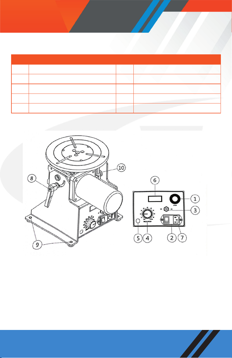
Equipment identification The identification number, model, and serial number of this unit can
be found on a nameplate attached to the control panel� Please record
these numbers for future reference�
Receipt of equipment Upon receiving the equipment, please check the shipping list� Make
sure it is complete and inspect the equipment for possible damage
during shipping� If there is any damage, notify the carrier immediately
to file a claim.
Safety Precautions
WARNING
Please be warned that operation and maintenance of the system
involve potential hazards� All operators and personnel should take
precautions to prevent possible injury�
Electrical safety Machine
•The counter, safety device against excess current and electrical
installation, are compatible with its maximum power and its main
voltage�
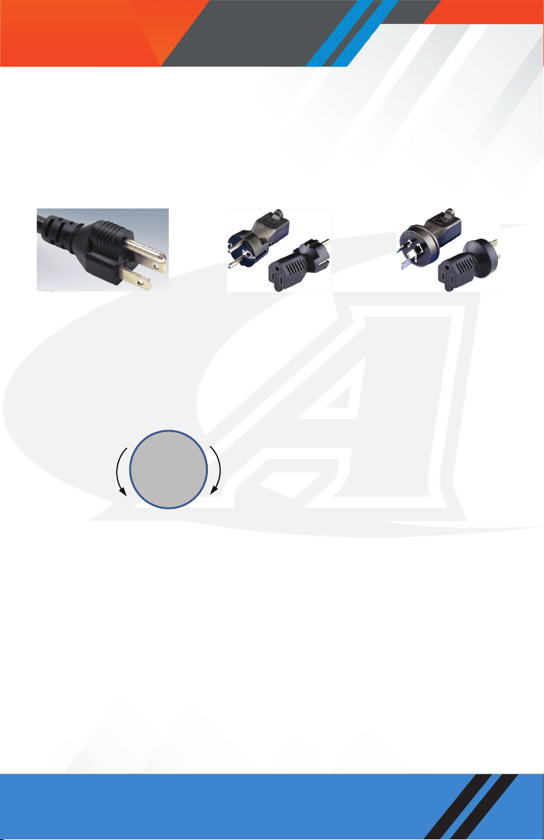
•The connection, single-phase or three-phase, is possible on a
stand compatible with the plug of its cable link�
•If the cable is connected with the electrical network, the earth
must never be cut by the protection device against electrical
shocks�
Work Place
•Avoid contact between metal part and phase conductor and the
neutral of electric network�
•Electrical messes of different electrical machine and apparatus
are connected between themselves and with the terminal of earth
neutral wire�
Interventions
•Before control and repair
, see the apparatus is switched off and
insulated�
•Connection with fixed installation cable is impossible.
•It’s on “Stop” and connection is impossible�
•Some apparatus areprovided with starting circuit HTHF(with a plate)�
Never enter into the corresponding switch cupboard�
•Only qualified persons are authorized for intervention concerning
electrical installation
Maintenance •Often check the insulation and connection good state of apparatus
and electrical accessories: taps, appliance cords, coatings, switch,
extension cords, etc�
• Maintenance and repair of insulating coatings operations are very
•important�
• Do repair with a specialist or better replace defective accessories�
•Check regularly the right adjustment and the non-heating of
electrical connections�