SAFETY INFORMATION
This symbol alerts you to the possibility
of serious injury or death if instructions
are not followed.
This symbol alerts you to the possibility
of damage to or destruction of equipment
if instructions are not followed.
Failure to heed these warnings may result in loss
of load, damage to the press and/or failure
resulting in property damage, personal or fatal
injury. This operating manual contains important details concerning the safe
operation of this tool. The user must read and understand these details
before any use of the tool. This manual must be retained for future reference.
• Read, study, and understand all instruction manuals packed with this
press before operating.
• Always wear safety goggles.
• Parts being pressed may splinter, shatter, or be ejected from the
press at a dangerous rate of speed. Because of the variety of press
applications, it is your responsibility to always use adequate guards
and wear eye protection and heavy protective clothing when operating
the press.
• Visual inspection should be made before each use of the press, checking
for signs of cracked welds, bent bed pins, loose or missing bolts, leaks,
or any other structural damage.
• Do not go near leaks. High pressure oil can puncture skin and cause
serious injury, gangrene, or death. If injured, seek emergency medical
help. Immediate surgery is required to remove oil.
• Keep hands and ngers out of the press and away from parts that may
shift and pinch. Do not stand in front of work area when load is applied.
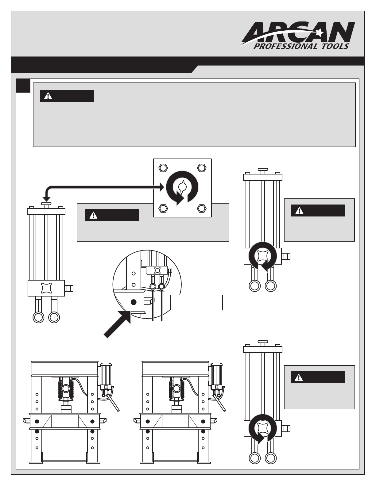
• Always use an accurate pressure gauge to measure pressing force.
• Do not exceed the rated capacity of this press.
• Never tamper with hydraulic system pressure settings.
• Do not substitute bolts, pins or any part of the components. Use only
genuine factory replacement parts.
• Always center load on ram plunger. Offset loads can damage ram and
may cause load to eject at a dangerous rate of speed.
• Remove all loads from press bed before attempting to adjust bed height.
Beware of possibility of falling bed.
• Press only on loads supported by press bed and included press plates.
Do not support loads on oor or press frame.
• When using any accessories such as arbor plates, be certain they are
centered on press bed and are in full contact with press bed.
• Before applying load, be certain all press bed supporting pins are fully
engaged.
• Always use a bearing shield when pressing bearings. Use caution when
positioning work to be pressed to ensure that the item that is to be
pressed cannot be dislodged or broken during press work. This may
result in the item being ejected from the press at a dangerous rate of
speed.
• Release hydraulic pressure before loosening any ttings.
• Maintain proper hydraulic uid levels.
• Do not make any alterations to the press.
OWNER/USER RESPONSIBILITY
The owner and/or user must have an understanding of the manufacturer's
operating instructions and warnings before using this press. Personnel
involved in the use and operation of equipment must be careful, competent,
trained, and qualied in the safe operation of the equipment and its proper
use when servicing motor vehicles and their components.
Warning information should be emphasized and understood.
If the operator is not uent in English, the manufacturer's instructions and
warnings must be read to and discussed with the operator in the operator's
native language by the purchaser/owner, making sure that
the operator comprehends its contents.
Owner and/or user must study and maintain for future reference the
manufacturer’s instructions. Owner and/or user is responsible for keeping all
warning labels and instruction manuals legible and intact. Replacement labels
and literature are available from the manufacturers.
INSPECTION
Visual inspection of the shop press should be made before each use of the
press, checking for damaged, loose or missing parts. Each press must be
inspected by a manufacturer’s repair facility immediately if subjected to an
abnormal load or shock. Any press which appears to be damaged in any way,
is found to be badly worn, or operates abnormally must be removed from
service until necessary repairs are made by a manufacturers's authorized
repair facility. It is recommended that an annual inspection of the press be
made by a manufacturer’s authorized repair facility and that any defective
parts, decals or warning labels be replaced with manufacturer’s specied
parts. A list of authorized repair facilities is available from the manufacturer.
SAFETY INSTRUCTIONS
• CHECK YOUR LOCAL, STATE AND FEDERAL REGULATIONS
REGARDING THE SAFE USE OF THIS EQUIPMENT.
• Your safety is a top priority. Please handle equipment with care.
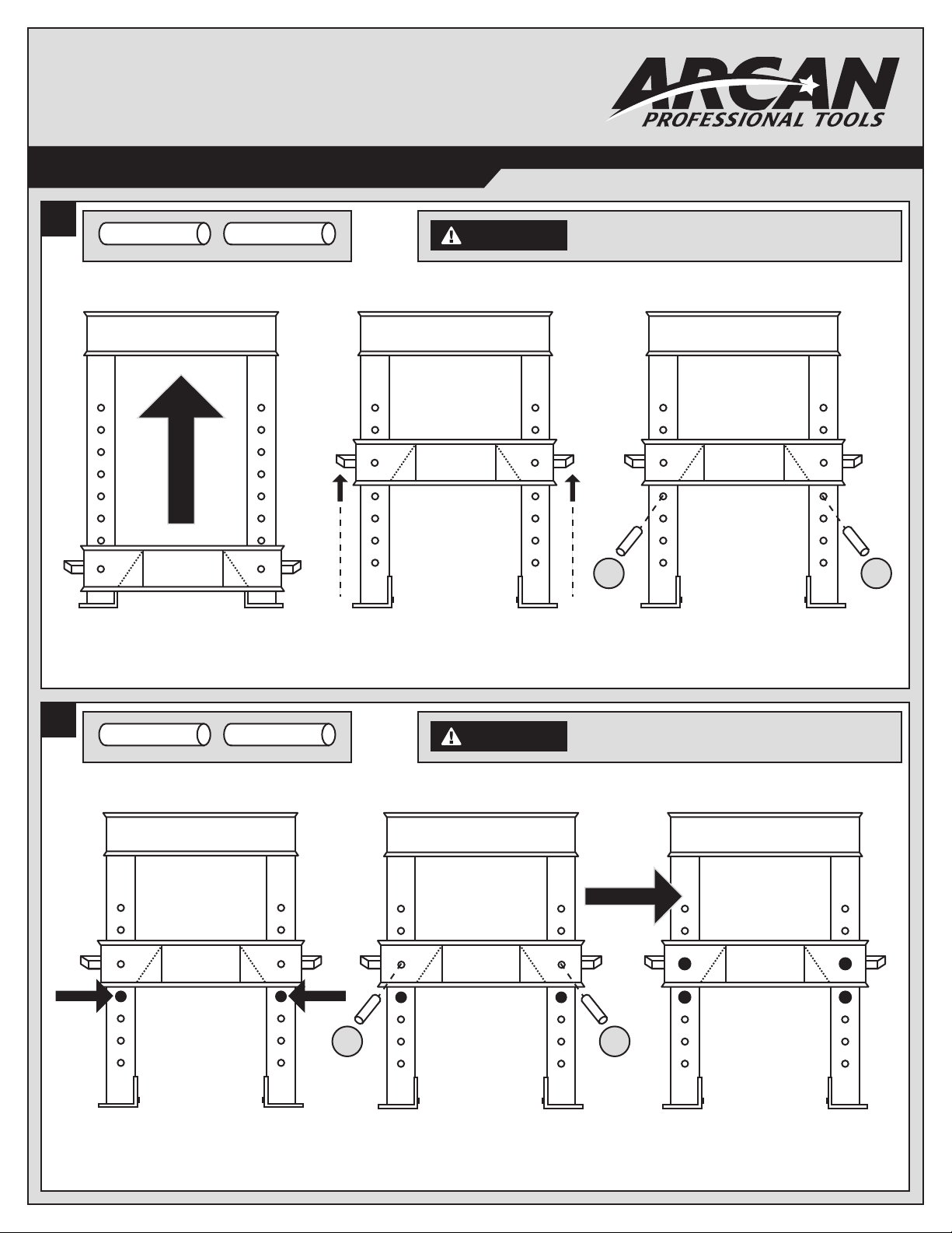
• Fully retract unit and remove all items from the press bed frame.
• Support the press bed and remove the pins.
• Raise or lower bed to desired height and reinstall press pins. Be certain
pins are fully engaged in the parallel anges of the upright columns.
• Position press on a at, level, hard surface, preferably concrete.
Make sure all nuts and bolts are tight.
• Clear the area of bystanders, especially small children, before using.
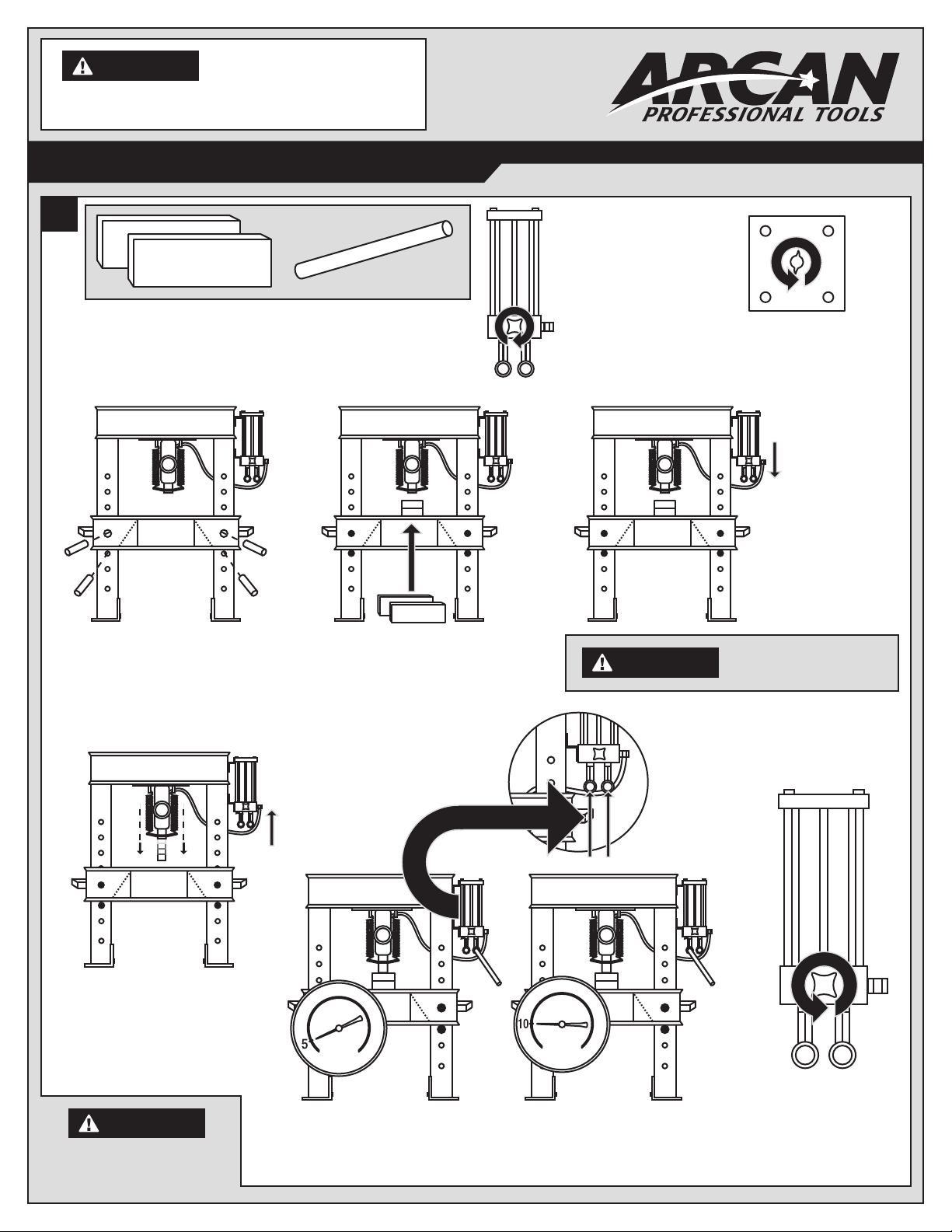
• Set the press bed to the required height. The press is most effective
when the work piece is located 1 inch below the ram’s retracted position.
The compression stroke can include the entire 5 inch working range.
• The press is designed to exert a force on anything which is positioned
beneath its ram. The work piece can be ejected from under the ram at
a high rate of speed and can injure someone.
• Pressing Bearings: It is essential that you use the bearing shield when
pressing bearings are on or off.
OPERATION
1. Press beds are adjustable up and down to fully take advantage
of available ram travel and numerous work pieces.
2. Slowly open release valve on power unit. With the power unit
in its stored position, remove all items from the press bed.
3. Be sure press bed is supported properly and remove press bed pins.
4. Raise or lower press bed to desired height, and reinstall press
bed pins. Be certain pins are completely through both sides
of frame, as these pins are the major support mechanism for the bed.
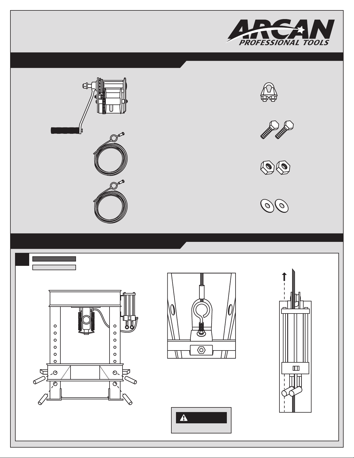
We want to know if you have any problems with our products.
If you are missing any parts or nd any damage, call Arcan directly,
and we will remedy the situation. Please do not call the store where
you purchased this product.
Phone: (800) 879-7316
WARNING
WARNING
CAUTION
CP400W Operation Manual 1