ARCC Abington User manual

USER GUIDE
+
1

www.arccbikes.com
01223 893 290
ARCC Innovations Ltd
Pampisford Road
Great Abington
Cambridge
CB21 6AH

A modern twist on a classic style.................... 3
Safety............................................................................. 5
Warning......................................................................... 6
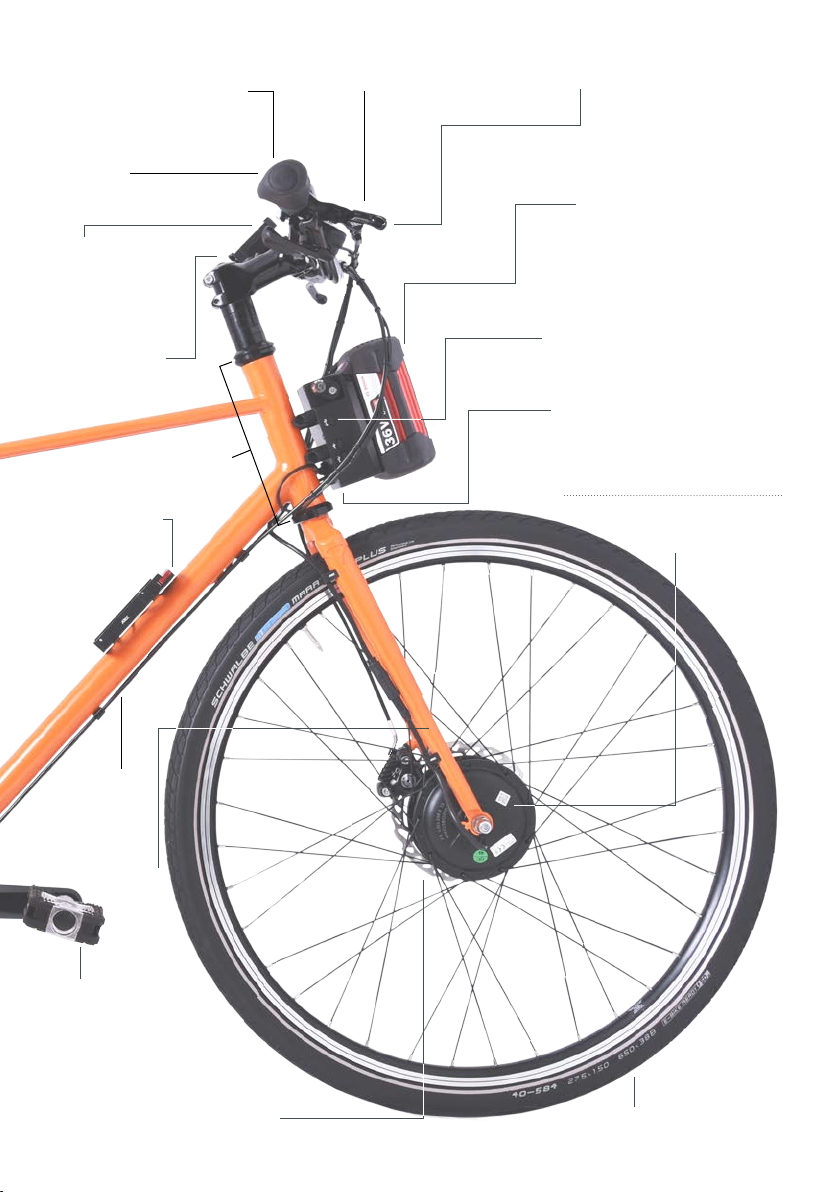
Component names................................................. 7
Unboxing and using your bike ........................... 9
Basic adjustments / maintenance................ 11
Gears........................................................................... 13
Brakes......................................................................... 14
Saddle Position...................................................... 16
Washing and cleaning your bike.................... 17
Front wheel removal - Electric........................ 18
............................ 19
Front wheel removal - Non-electric............. 20
......... 21
.............. 23
Rear wheel removal - Single Speed............. 24
.......................... 25
............................... 26
Belt removal - Gates Carbon Drive .............. 27
Bottom bracket...................................................... 28
Torque settings...................................................... 29
.................................................... 30
Options list............................................................... 33
Using the e-pod................................................... 34
Technology, meet simplicity............................ 36
Unboxing the e-pod........................................... 37
Checking and charging the battery............. 38
Docking the battery............................................. 39
Removing the battery ......................................... 40
Using the USB-C ports ...................................... 41
LED Indicators........................................................ 42
Using the e-pod app ......................................... 43
Using the Bluetooth controller....................... 47
Trouble shooting guide...................................... 49
Declaration of conformity................................. 51
Warranty.................................................................... 52
Warranty terms and conditions ..................... 53
Contact us................................................................ 56
About ARCC Innovations.................................. 57
Contents
2

Meet the Abington; a sleek town bike; and the
Rosemont, a lightweight step-through bike designed
in collaboration with award winning frame builder Toby
Gallagher. They combine the elegance and poise of a
bygone era, with state-of-the-art engineering at ARCC
Bikes.
Reynolds Technology steel tubing, and are hand brazed
in Cambridge, UK. Machined stainless steel dropouts
allow for a variety of drivetrain options, and combine
with large 650b x 38 tyres to provide a wonderfully
comfortable, yet responsive ride.
Available with or without ARCC’s renowned e-pod
Intelligent Drive System and in a range of colours,
The ARCC e-pod Intelligent Drive System has been
designed by ARCC Innovations to provide unique
intelligent bike power and is available for all ARCC
frames.
It combines variable power levels with automatic
hill/gradient compensation and launch control. This
allows commuting cyclists to choose the amount of
compensates for hills and gradients; and provides
‘launch control’, for safety when moving away from
Your ARCC bike equipped with the ARCC epod
Intelligent Drive System is ideal for commuting or fast
on road riding, delivering a well-tuned, responsive ride
everywhere you go.
A modern twist
on a classic style
3

4

Safety
Introduction
Before using your ARCC bike please read this manual, noting the sections on safety in
particular. While this manual is intended as a guide to the bicycle, it is not a comprehensive
guide to cycling or bicycle maintenance.
If you carry out any adjustments or maintenance work yourself, please read the relevant
avoid damaging your bike.
This manual contains some tips and advice for using your ARCC bike but if you are ever
unsure of how to maintain your bike, please contact the retailer where you made your
purchase or call ARCC for expert advice.
Intended use
The bike is designed for use on roads and well-made paths, carrying a maximum load not
whilst also ensuring that the child seat complies with EN 14344.
The bike is not intended for drops of more than 100mm, stunts, cross-country riding or
extreme sports. Misuse may lead to failure of some components and void your ARCC
warranty.
Specication
This bike and manual conforms to ISO 4210-2 and EN 15194. For electric bikes, the motor
assistance is limited to a maximum continuous power rating of 0.25 kW (250 W) and a
maximum speed of 25km/h, (15.5mph). The A-weighted emission sound pressure level at
the driver ears is less than 70dB(A).
For your safety
Before riding your ARCC bike please consider the following:
• Take the time to familiarise yourself with the operation of the bicycle in a quiet place
• We recommend the use of an approved cycling helmet.
• Read and follow the national legal requirements of the country where you are riding, and
• Check brakes, tyres and steering regularly.
• Keep brakes and gears properly adjusted and operating cables in good condition.
•
to brake sooner.
• Check that all wheel nuts are properly tightened (see ‘Torque settings’).
5

of a component has been exceeded, it may suddenly fail, possibly causing injuries to the rider. Any
form of crack, severe scratches or change of colouring in highly stressed areas indicate that the
life of the component has been reached and it should be replaced.
-pod, the electrical system including the software should not be
-pod should not be opened,
You should stop using the bike immediately and have the bike inspected by a bicycle technician if it
has been subject to a crash or impact. Damaged components should be replaced before the bike
is ridden again.
Note: We recommend that genuine replacement parts are used for safety-critical components.
Please call us for expert advice if you are uncertain on any of the above.
Warning
• Note that in the UK, the left hand brake lever operates the rear brake and the right hand
lever operates the front brake, but this varies from country to country.
•
lights; check to ensure that your lights comply with local laws.
• Ensure that the seat post clamp is secured (Torque 8Nm) and the saddle is at the
correct height (see ‘Basic adjustments/maintenance’).
On electric models:
• Ensure you do not drop the battery as it could cause damage to the battery itself.
•
• Ensure the battery is properly secured before using the bike.
• Read and follow the national legal requirements of the country where you are riding
in relation to cycling, bicycles, and electric assisted bicycles, and comply with all
• Do not use the bike if there is any problem with the e-pod Intelligent Drive System,
take the bike to ARCC Bikes or to the retailer from which you purchased your bike, for
inspection.
6

Bottom Bracket
(Torque sensor e-bike only)
brake - 140mm
brake - 160mm
Shimano single speed/
Rear wheel
Seat post
Saddle clamp Seat post
clamp
Handlebar stem
Gates Carbon Drive
belt and crank set
Saddle
650b x 38 tyres
Component names
Frame
7

Bosch battery
(e-bike only)
ARCC e-pod
(e-bike only)
Shimano quick release hub
(Non-electric bike only)
250W Motor
(e-bike only)
Handlebars
Grips
Fork
Brake switches
(e-bike only)
Spare battery
holder
(e-bike only)
Brake / gear
cables
Flat mount disc brake -
160mm Front wheel
Brake levers
Headset
Handlebar stem
Bluetooth
controller
(e-bike only)
USBC ports
(e-bike only)
Component names
Pedal
8

Unboxing and using
your bike
1. Fitting the pedals
3. Use a 15mm spanner to tighten the
pedal in place.
1. Identify the correct pedal from the ‘L’ and ‘R’ indicators found on the pedal stem. The
‘L’ refers to the left pedal and the ‘R’ refers to the right pedal when viewed from the riding
position.
2. Place and rotate the stem of the pedal
into the crank arm and rotate. Rotate the
left pedal anti-clockwise to tighten and
the right pedal in a clockwise motion to
tighten.
9

4. Gears
model you selected when ordering. Please refer to the ‘Gears’ section of this user guide and
5. Brakes
You should adjust your brakes on a regular basis as they are critical to your safety. The time
between adjustments will vary dependant on how often you use your ARCC bicycle; if your
brake lever touches the handle bar when you pull on it, your brakes need urgent adjustment.
technician. For further information please see the ‘Brakes’ section of this user guide.
6. Lubrication
We recommend lubrication of only the headset on your ARCC bicycle. Ensure this is done by a
trained professional during your general service.
7. Initial service
technician at your local bike shop.
8. General services
technician to ensure that it is as safe to ride as possible.
Marathon Plus
Minimum Tyre Pressure Maximum Tyre Pressure Recommended Tyre Pressure
Front 55 95 80
Rear 55 95 80
2. Adjusting the handlebars
Rotate the handlebar stem so that it is in line with the front wheel
facing forward. Once you have tightened the two steerer tube
stem bolts to 9Nm, loosen the four stem face plate bolts. This
will allow you to rotate the handlebars to a desired position - it
is important to tighten the stem face place bolts evenly to 8Nm
once you are happy with the adjustment.
3. Tyre pressures
Tyre pressure is important for both comfort and safety. Please
note the following tips for ensuring a safe and comfortable ride.
•
is highly recommended.
• The most appropriate pressure depends on your weight and preference. On rough
roads, it’s often more comfortable to keep the pressures near the lower end of the
• For best performance with the e-pod we recommend high pressure tyres.
•
The following table shows recommended tyre pressures for your ARCC bike.
Stem face
plate bolts
Steerer tube
stem bolts
10

1. Saddle height adjustment
Saddle position is a personal choice meaning one saddle cannot suit everyone, but with
some adjustment, a comfortable saddle position can be found for any user.
Vertical adjustment
• To check for the correct saddle height to suit you, sit on the saddle with one heel on a
pedal and the crank arm positioned at the bottom of the stroke parallel to the seat post.
If your leg is not completely straight, your saddle height needs to be raised.
• When riding normally, with the ball of your foot on the pedal, your knee should be slightly
• Once positioned, tighten the seat post clamp bolt to the correct torque of 8Nm.
• The seat post must not be extended beyond the minimum insertion point marked on
the seat post.
2. Saddle fore and aft adjustment
The saddle can be adjusted forwards or backwards to help achieve the optimal position
on the bike. Move the saddle forwards to get closer to the handlebars and backwards to
increase the reach. Always tighten the saddle clamp bolt to the correct torque of 22Nm
before riding your ARCC bike.
3. Saddle angle adjustment
Whenever you adjust the saddle angle, always tighten the saddle clmap bolt to the correct
torque of 22Nm before riding your ARCC bike. Refer to the ‘Saddle Position’ section of this
manual for more information.
4. Handlebar position
The handlebars can be tilted towards and away from the rider. Whenever you adjust the
handlebars, always tighten the four stem face plate bolts to the correct torque of 8Nm
before riding the bike.
5. Routine replacements
Routine replacements are advised to ensure both safety and good performance. The
suggested intervals between replacements are for bicycles subjected to normal use; the
most appropriate timing depends on the conditions of use and riding style. We recommend
only genuine replacement parts for safety-critical components.
• Brakes cables
damaged. New outer cables should be exactly the same length as the original; ensure to
of your bicycle.
Basic adjustments /
maintenance
11

• Gear cables
• Disc pads should be regularly inspected to check that there is 1.5mm of pad visible on
either side (2 pads in total).
• Tyres become increasingly likely to get punctures as the tyre tread starts to wear away.
Once you notice your tyre tread wearing thin, replace the tyre. This will reduce your
5. Belt tensioning
Please refer to the Gates Carbon Drive documentation for information on belt tensioning.
12

Gears
Shimano features
• A two-way self-returning lever
• Gear indicator window helps you to see which gear to select
• Available in single speed, 8-speed and 11-speed
Using the Shimano gearing
The shifter uses a simple-to-use self-returning lever to change between gears. Pushing
back of the thumb will shift into a higher gear. It is important to stop pedalling or back pedal
slightly when changing gear. The indicator window shows you which gear is selected.
Rohlo features
• A smooth twist motion to change gears (Grip Shift)
• Gear indicator markings are clearly marked on the shifter
• 14-speed
Using the Rohlo gearing
The shifter is manually operated using a twisting motion to switch between gears. It is
important to stop pedalling or back pedal slightly when changing gear. The marks on the
grip shift indicate which gear is selected.
Shimano
13

Brakes
You should adjust your brakes on a regular basis as they are a critical component for safety
on your bike. The time between adjustments will vary dependent on how often the bike is
used, if the brake lever touches the handlebar when you pull on it, this is an indication that
your brakes need urgent adjustment. The brakes should be set so that there is a 1.5mm gap
on either side of each brake pad. Adjustment is carried out using the threaded cable stop
technician or at ARCC Bikes.
Brake lever adjustment
In order to achieve a comfortable and safe brake lever position, it is important to spend time
ensuring that the lever is correctly adjusted. You can adjust the distance of the lever from
Handlebar clamp bolt 8Nm
(this can be found on the
underside of the bike)
Lever blade Lever body
Lock ring
Barrel adjuster
Cable
housing
Reach
adjuster
IN OUT
14

Brakes
Lever angle
The range of lever angle adjustment is restricted by the cable exit path, if the lever is angled
too high it will cause problems for the operation of the brakes.
Lever position
The position of the lever on the bar can be adjusted to move the lever closer or further from
the end of the handlebar grip. This adjustment will allow the lever to be positioned for one,
braking force but reduce bar grip.
Reach adjuster
Lever reach adjustment is controlled by the grub screw on the side of the lever body.
Screwing the reach adjuster into the lever body will bring the lever closer to the handlebar.
When the lever reach is adjusted closer to the handlebar it will cause the brake pads
to move closer to the disc rotor. It may be necessary to adjust the lever bite point
screwing the barrel adjuster into the lever body.
a satisfactory lever bite point, you may need to loosen the cable camp bolt situated on the
brake calliper to allow some cable to be pulled through. Be sure to re-tighten this bolt to
8Nm and ensure the cable is properly secured before using the bike.
Bite-point adjustment
Lever bite-point (engagement position) adjustment is controlled by the barrel adjuster.
Screwing the barrel adjuster into the lever body will bring the lever-bite-point closer to the
handlebar. Screwing the barrel adjuster outward from the lever body will move the bite point
further from the handlebar.
The barrel adjuster uses a lock ring to secure it into position; this should be loosened before
adjustment and tightened once the barrel adjuster is correctly positioned.
15

Saddle position
Both the angle and the fore-aft position of the saddle can be adjusted. To establish the most
comfortable position you should start by adjusting the saddle into a neutral position, you
clamp bolt using a 6mm hex key until the saddle can be moved with little force. Be careful
Move the saddle rails in the clamp so that they are roughly centred (half way between
maximum fore and aft position). Adjust the saddle into a level position, so that the top
surface of the saddle is roughly level between the front and rear edge (Fig.1). Once the
saddle is in a neutral position, tighten the seat clamp bolt to 22Nm. Test the saddle position,
you can adjust to make it more comfortable.
Angle
If the nose feels like it is pointing up or as though the back of the saddle isn’t giving enough
support, you can angle the saddle forward. Once you have adjusted the saddle, tighten the
saddle clamp bolt, test by riding, and then readjust if necessary.
Fore-aft position
the handlebars but also the
position relative to the pedals.
By moving the saddle back,
you will increase the reach to
the handlebars, moving the
saddle forward will decrease
the reach to the handlebars
and force a more upright rider
position.
Fig.1
16

Washing and cleaning
your bike
When cleaning your bike - electric or non-electric - do not use a jet wash or high pressure
hose to clean the bike, e-pod, battery, motor, bottom bracket or rear hub (indicated
electronics, causing premature failure. You should hand wash only with a suitable bike
cleaner or warm soapy water and a damp cloth.
Whilst the e²-pod Intelligent Drive System has been designed for use in all weathers, the
electrical components of the bicycle such as the motor, bottom bracket, battery and the
e²-pod must not be submerged in water.
Battery and charger
See the accompanying Bosch battery and charger manuals for recommendations on
cleaning.
The charger must be unplugged from the mains outlet socket before cleaning.
Bike frame and components
The battery should be removed before cleaning the bike frame and its components.
battery to the bike.
Fig.2
17

Front wheel removal
Electric
1. Remove the electrical cable from the cable clips. Locate the motor electrical
connector on the bicycle forks. Hold each side of the connector and pull apart in a
straight line, ensure you do not twist or over-strain the connectors.
2. Loosen the two wheel nuts from both
sides of the fork, and drop the wheel
away from the frame.
Cable clip
Motor electrical
connector
18

Electric
1. Ensuring the dog washer and cable are facing down, slot the wheel
back into the forks.
2. Tighten the two wheel nuts. Then, ensuring that the two marked arrows
clips.
Dog washer
19
This manual suits for next models
1
Table of contents
Other ARCC Bicycle manuals