Interfaccia di controllo DMX » LSDMX Manuale Utente
I
ATTENZIONE! Prima di eettuare qualsiasi operazione con l’unità, leggere con attenzione questo manuale e conservarlo accuratamente per
riferimenti futuri. Contiene informazioni importanti riguardo l’installazione, l’uso e la manutenzione dell’unità.
Le informazioni riportate in questo manuale sono state attentamente controllate. Music & Lights non si assume, tuttavia, responsabilità derivanti da eventuali inesattezze.
Tutte le speciche possono essere variate senza alcuna notica
Per
qualsiasi
nec
essità
si
prega
di
contattare
il
nostro
ucio
tecnic
o:
tel.
+39
0771
72190
fax
+39
0771
721955
-
[email protected]Rev003 - 11/11 ©2011 Music & Lights S.r.l. - Italy - www.musiclights.it
power
adapter
3 Pin signal wires
DMX512 Console
AC110V~230V
AC110V~230V
DC12V~24V
DIP Switch DMX512IN DMX512OUT
DMX512OUT
Ch1 com V+ V-
-+
Ch2Ch3
R1
R2
R3
power
adapter
AC110V~230V
DC12V~24V
DIP Switch DMX512IN DMX512OUT
Ch1 com V+ V-
Ch2Ch3
R1
R2
R3
power
adapter
AC110V~230V
DC12V~24V
DIP Switch DMX512IN DMX512OUT
Ch1 com V+ V-
Ch2Ch3
R1
R2
R3
3 Pin signal wires 3 Pin signal wires
INPUT OUTPUT
V- V+
COM
CH1
CH2
CH3
Nero
Rosso
Power
Verde
Blue
Avvertenze generali
• I prodotti a cui questo manuale si riferisce sono conformi alle Direttive della Comunità
Europea e pertanto recano la sigla . • Il dispositivo funziona con tensione DC12V~24V; non
connettere ad alimentazione AC220V. Inoltre, non intervenire mai al suo interno al di fuori
delle operazioni descritte nel presente manuale; esiste il pericolo di una scarica elettrica.
• È obbligatorio eettuare il collegamento dell’adattatore di tensione ad un impianto di
alimentazione dotato di un’eciente messa a terra (apparecchio di Classe I secondo norma
EN 60598-1). Si raccomanda, inoltre, di proteggere le linee di alimentazione delle unità
dai contatti indiretti e/o cortocircuiti verso massa tramite l’uso di interruttori dierenziali
opportunamente dimensionati. • Le operazioni di collegamento all’alimentazione
devono essere eettuate da un installatore elettrico qualicato. Vericare che la tensione
corrisponda a quella per cui l’unità è predisposta, indicata sull’etichetta dei dati elettrici. •
L’unità non per uso domestico solo per uso professionale. • Evitare di utilizzare l’unità: - in
luoghi soggetti ad eccessiva umidità; - in luoghi soggetti a vibrazioni, o a possibili urti; -
in luoghi a temperatura superiore ai 60°C od a -20°C. • Evitare che nell’unità penetrino
liquidi inammabili, acqua o oggetti metallici. • Non smontare e non apportare modiche
all’unità. • Tutti gli interventi devono essere sempre e solo eettuati da personale tecnico
qualicato. Rivolgersi al più vicino centro di assistenza tecnica autorizzato. • Se si desidera
eliminare il dispositivo denitivamente, consegnarlo per lo smaltimento ad un’istituzione
locale per il riciclaggio.
Attenzioni e precauzioni per l’installazione
• Nell’eseguire qualsiasi intervento attenersi scrupolosamente a tutte le normative, in
materia di sicurezza, vigenti nel paese di utilizzo. • Se il dispositivo dovesse trovarsi ad
operare in condizioni dierenti da quelli descritte nel presente manuale, potrebbero
vericarsi dei danni; in tal caso la garanzia verrebbe a decadere. Inoltre , ogni altra
operazione potrebbe provocare cortocircuiti, incendi, scosse elettriche, rotture ect. • Prima
di iniziare qualsiasi operazione di manutenzione o pulizia disconnettere l’unità dalla rete
di alimentazione. • Non toccare i cavi di alimentazione con le mani bagnate. • Mantenere
materiali inammabili ad una distanza di sicurezza dall’unità. • Per la pulizia usare solo un
panno morbido, asciutto, non impiegare in nessun caso prodotti chimici o acqua.
Descrizione e speciche tecniche
Interfaccia di controllo DMX per stringhe LEDSTRIP.
• Controllo manuale attraverso tastiera dip-switch per cambio di colori o esecuzione di
scene automatiche.
• Selezione dei canali di uscita DMX per il collegamento di unità di controllo esterne.
• Modalità di funzionamento a 3 canali.
• Connessioni di ingresso: spina XLR-3p, presa RJ45.
• Connessioni di uscita: presa XLR-3p, presa RJ45.
• Massima corrente di uscita: 3x4A
• Massima potenza: 3x48W (144W)
• Dimensioni: 165x75x40 mm
Installazione
L’interfaccia di controllo LSDMX deve essere collocata e ssata in modo stabile su una su-
percie piana non inammabile per mezzo delle due viti che devono essere inserite negli
appositi fori sul corpo del dispositivo.
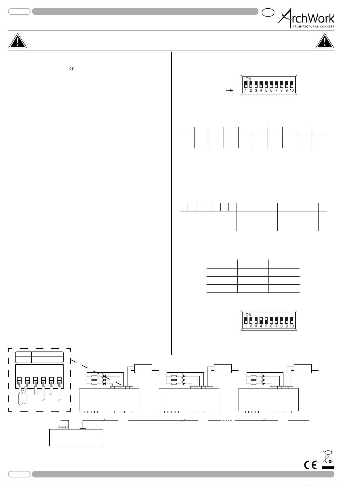
Collegamento
Dopo aver eettuato il collegamento dell’interfaccia LSDMX all’alimentazione (DC12V~
24V), collegare l’unità con gli altri dispositivi nelle modalità indicate nel g.1. Per il colle-
gamento con gli altri dispositivi, l’unità dispone oltre che di connettori XLR a 3 poli, anche
di connettori RJ45.
Funzioni e impostazioni
L’interfaccia LSDMX dispone di un pannello di controllo costituito da un modulo DIP-
switch (g.2). Ciascuno dei singoli switch dispone di un numero (DIP switch [1] a [10]).
Numero switch Fig.2
Fig.1
Modalità di funzionamento Manuale
Per impostare la modalità manuale è necessario posizionare i DIP-switch [8] e [9] su “OFF”
e il DIP-switch [10] su “ON”. I DIP-switch [1 - 7] consentono la scelta dei colori secondo la
tabella riportata di seguito:
DIP-switch
12345678910
Red Green Blue Yellow Purple Cyan White OFF OFF ON
DIP-switch
1234567 8 9 10
SPEED (Slow - Fast)
SHOW
(Seven-color jumpy
changing eect)
SHOW
(Seven-color gradual
changing eect)
ON
NOTA - Per i DIP-switch posizionati su “ON”, la priorità è attribuita al DIP-switch con valore
maggiore.
Modalità di funzionamento Automatica
Per impostare la modalità automatica è necessario posizionare il DIP-switch [10] su “ON”.
Successivamente è possibile scegliere tra due programmi automatici che possono esse-
re impostati posizionando rispettivamente il DIP-switch [8] o [9] su “ON”. Per entrambi i
programmi automatici impostare la velocità di esecuzione, da lento a veloce, attraverso
i DIP-switch [1 - 7].
Modalità di funzionamento DMX
Per impostare la modalità automatica è necessario posizionare il DIP-switch [10] su “OFF”.
Come interfaccia DMX, l’unità dispone di connettori XLR a 3 poli e connettori RJ45. Far
riferimento alla tabella seguente che riporta le funzioni e i relativi valori DMX.
Il modo più semplice è quello di partire sempre dal massimo valore possibile aggiungendo
i valori minori no a raggiungere, come somma, l’indirizzo desiderato.
Esempio:
Indirizzo 24 = switch n°4 e 5 su ON
1
2
4
8
16
32
64
128
256
Fig.3
L’indirizzo viene impostato come numero binario per mezzo dei DIP-switch n° 1 - 9. Quindi,
risulta dall’addizione dei valori dei DIP-switch posizionati su ON.
Channel Function DMX value
1 RED 0-100% 000 - 255
2 GREEN 0-100% 000 - 255
3 BLUE 0-100% 000 - 255