3
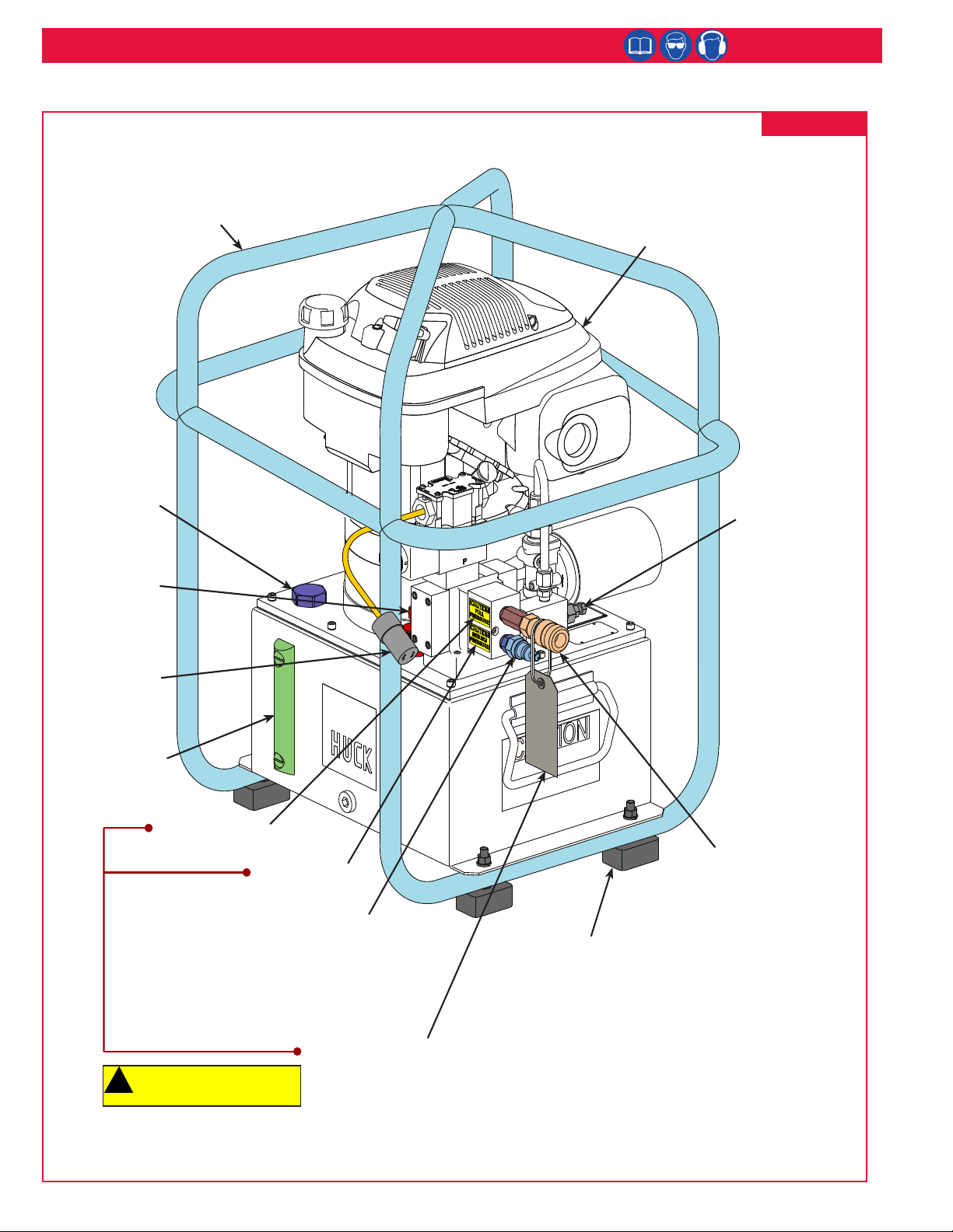
913F Powerig® Unit (HK1191)
1.
personnel is recommended before using Huck equipment.
2. Huck equipment must be maintained in a safe working
condition at all times. Tools and hoses should be inspected
at the beginning of each shift/day for damage or wear. Any
Huck procedures.
3. Repairman and Operator must read manual prior to using
equipment. Warning and Caution stickers/labels supplied
with equipment must be understood before connecting
equipment to any primary power supply. As applicable, each
information.
your Huck representative.
5. When repairing or operating Huck installation equipment,
always wear approved eye protection. Where applicable, refer
to ANSI Z87.1 - 2003
6. Only genuine Huck parts shall be used for replacements or
spares. Use of any other parts can result in tooling damage or
personal injury.
are missing or damaged, the end user is responsible for
replacement. Refer to assembly drawing and parts list for
replacement part number and proper placement.
8. Disconnect primary power source before performing
maintenance on Huck equipment or changing Nose Assembly.
9. Tools and hoses should be inspected for leaks at the
beginning of each shift/day. If any equipment shows signs of
damage, wear, or leakage, do not connect it to the primary
power supply.
10. Mounting hardware should be checked at the beginning of
each shift/day.
11. Make sure proper power source is used at all times.
12. Release tool trigger if power supply is interrupted.
installed and operating prior to use.
16. Never install a fastener in free air. Personal injury from
fastener ejecting may occur.
17. Where applicable, always clear spent pintail out of nose
18. There is possibility of forcible ejection of pintails or spent
mandrels from front of tool.
19. Check clearance between trigger and work piece to ensure
there is no pinch point when tool is activated. Remote
triggers are available for hydraulic tooling if pinch point is
unavoidable.
20. Unsuitable postures may not allow counteracting of normal
21. Do not abuse tool by dropping or using it as a hammer.
Never use hydraulic or air lines as a handle or to bend or pry
the tool. Reasonable care of installation tools by operators is
downtime, and in preventing an accident which may cause
severe personal injury.
22. Never place hands between nose assembly and work piece.
Keep hands clear from front of tool.
23. There is a risk of crushing if tool is cycled without Nose
Assembly installed.
24. Tools with ejector rods should never be cycled with out nose
assembly installed.
25. When two piece lock bolts are being used always make sure
the collar orientation is correct. See fastener data sheet for
correct positioning.
26. Tool is only to be used as stated in this manual. Any other
use is prohibited.
27. There is a risk of whipping compressed air hose if tool is
pneudraulic or pneumatic.
28. Release the trigger in case of failure of air supply or hydraulic
supply.
30. Disposal instruction: Disassemble and recycle steel, aluminum
accordance with local lawful and safe practices.
is secure prior to operating the tool.
32.
in hydraulic equipment can cause an injection injury which
could result in tissue damage, amputation or even death.
Work gloves will not protect against pinhole leaks. Before
each use of hydraulic equipment, inspect with pressure
relieved. Replace any worn or damaged hydraulic parts
immediately with items recommended for the application by
the original manufacturer.
less chance long-term disability will occur.
Safety Instructions
GLOSSARY OF TERMS AND SYMBOLS:
- Read manual prior to using this equipment.
- Eye protection is required while using this
equipment.
- Hearing protection is required while using this
equipment.
Notes: are reminders of required procedures.
Bold, Italic type, and underline:
instruction.
WARNINGS: Must be understood to avoid
severe personal injury.
CAUTIONS: Show conditions that will
damage equipment or structure.
Where the following trade names are used in this manual, please note:
DEXRON is a registered trademark of General Motors Corporation.
GLYD Ring is a registered trademark of Trelleborg Sealing Solutions Germany GmbH
Loctite is a registered trademark of Henkel Corporation, U.S.A.
LUBRIPLATE is a registered trademark of Fiske Brothers Rening Co.
MERCON is a registered trademark of Ford Motor Corp.
MOLYKOTE is a registered trademark of Dow Corning Corporation
Never-Seez is a registered trademark of Bostik, Inc.
Quintolubric is a registered trademark of Quaker Chemical Corp.
Slic-tite is a registered trademark of LA-CO Industries, Inc.
Spirolox is a registered trademark of Smalley Steel Ring Company
Teon is a registered trademark of Chemours Company FC.
Threadmate is a registered trademark of Parker Intangibles LLC.
TRUARC is a trademark of TRUARC Co. LLC.
Vibra-Tite is a registered trademark of ND Industries, Inc. USA.