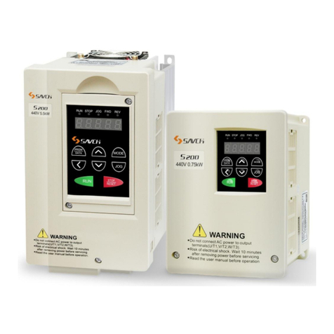
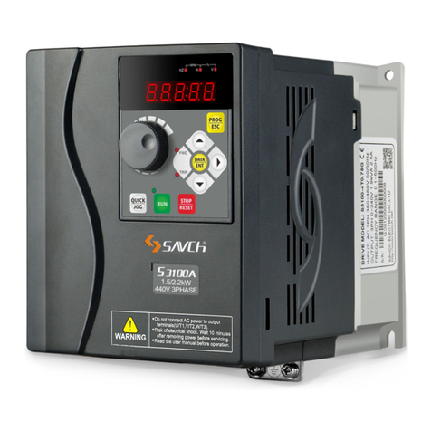
Savch S3100A Series User manual

S3100A series inverter
General Open-loop Vector Control (IM)
User manual
User Manual

S3100A series inverter
General Open-loop Vector Control (IM)
User manual
File No. 520031128082
Vision No. V1.2
Filing time 2021-08-17
SAVCH electric provide a full range of technical support for our customers.
All users could contact with the nearest SAVCH office or service center,
also could contact with our headquarters directly.
SAVCH Electric reserves the copyrights and all rights,
Subject to change without further notice.

CONTENTS
PREFACE......................................................................................................................................................... 1
1 SAFETY INSTRUCTIONS ......................................................................................................................... 2
1.1 Notes for Operation............................................................................................................................ 2
1.2 Notes for Operation Environment .................................................................................................. 4
2 HARDWARE DESCRIPTION AND INSTALLATION............................................................................. 4
2.1 Operational Environment.................................................................................................................. 5
2.2 Model Description............................................................................................................................... 5
2.3 Inverter Specifications ...................................................................................................................... 7
2.4 Basic Wiring Diagram ...................................................................................................................... 15
2.5 External Dimensions........................................................................................................................ 17
2.5.1 Inverter Size................................................................................................................................. 17
2.5.2 Extemal Dimensions of Inverter............................................................................................. 18
2.5.3 Multi-Functions Operation Keypad ....................................................................................... 23
3 KEYPAD DESCRIPTION ......................................................................................................................... 25
3.1 Keyboard Description for HCA-OP-A2 / HCA-OP-B2 Digital Operator ............................... 25
3.2 Description of Keyboard Operation............................................................................................. 27
3.2.1 Parameter Setting ...................................................................................................................... 27
3.2.2 Failure Resetting ........................................................................................................................ 28
3.2.3 Motor Parameter Self-learning ............................................................................................... 28
3.2.4 Password Setting....................................................................................................................... 28
3.2.5 Running State ............................................................................................................................. 29
3.2.6 Quick Debugging ....................................................................................................................... 30
3.3 Preliminary Operation-not Connecting With Motor................................................................. 31
4 FUNCTION PARAMETERS LIST ........................................................................................................... 33
5 DESCRIPTION OF FUNCTIONAL PARAMETERS ............................................................................ 60
00 Basic Functions Parameters........................................................................................................... 60
01 Motor Control Parameters............................................................................................................... 69
02 Vector Control Parameters.............................................................................................................. 71
03 V/f Control Parameters..................................................................................................................... 73
04 Input Terminal Parameters .............................................................................................................. 77
05 Multi-Speed, Simple PLC Control.................................................................................................. 87
06 Output Terminal Parameters........................................................................................................... 92
07 Start and Stop Control Parameters............................................................................................... 96
08 Man-machine Interface Parameters ............................................................................................ 100
09 Accessibility Parameters ............................................................................................................... 104
10 PID Control Parameters.................................................................................................................. 115

11 Fault and Protection Parameters ................................................................................................. 120
12 Serial Communication Parameters ............................................................................................. 127
13 Wobble Frequency Counting Parameters ................................................................................. 135
17 Torque Control Parameters........................................................................................................... 137
22 Control Optimization Parameters................................................................................................ 138
99 Monitoring Parameters ................................................................................................................... 140
6 TROUBLE SHOOTING .......................................................................................................................... 141
6.1 Failures & Failure Elimination ..................................................................................................... 141
6.2 General Troubleshooting Method............................................................................................... 144
7 MAINTENANCE AND AMBIENT ELEMENTS................................................................................... 145
7.1 Braking Resistor Selection Guide .............................................................................................. 147
7.2 Breaker,Cable and Contactor Specifications List.................................................................. 150
7.3 Input/Output AC Reactor and DC Reactor Specifications................................................... 151
7.4 Input/Output Filter Specifications .............................................................................................. 152

1
PREFACE
Thank you for choosing SAVCH inverter! This instruction manual, which includes operation descriptions and
notes for maintenance, shall be delivered to the end-user.
For safety running and effective operation, this instruction manual shall be read thoroughly prior to use,
which shall also be preserved for later use. Provided problems occur and solution is not provided in this
instruction manual, contact your SAVCHELECTRIC representative or contact with our company directly. Our
professional technicians will serve for you actively. And please continue to adopt products of SAVCH, give
valuable opinion and advice.
1.Reading Instructions
Symbols of” DANGER” and” CAUTION” in the manual indicates that, for safety running or maintenance of
inverters or other electrical products, attention shall be attached during delivering, installation, operation and
checks for the inverter. And these notes shall be applied for a better and safer operation.
DANGER
If not used correctly, personnel damage even death may be caused.
△
!CAUTION
If not used correctly, serious damage to inverter or machine may be resulted.
DANGER
●Never connect wires while power on. Do not check components or signal for circuit board during operation.
●Do not dismantle or change inner wire, circuit or components unnecessarily.
●Make sure grounding terminals are correctly grounded. 220V level:Grounding Ⅲ,440V special grounding.
△
!CAUTION
●Do not perform a withstand voltage test for components of inverter, it can cause semi-conductor
components to be damaged by high voltage.
●Never connect the output terminals U, V, W to AC power supply.
●IC of CMOS on control circuit of the inverter shall be damaged by electrostatic influence. Do not touch main
circuit board.
2.Products Receiving
All products have been performed with strict test and inspection. After receiving the inverters, the following checks
shall be performed.
●To check that SAVCH inverter, an instruction manual and a cover is inside of the package
●To check whether model number correspond with model and capacity your purchase order.
●To check whether there are damaged parts during transportation and delivering. If there are, do not connect
with power supply.
●If any of the above checkpoints are not satisfactory, contact your SAVCHELECTRIC representative for a quick
resolution.

2
1 SAFETY INSTRUCTIONS
1.1 Notes for Operation
Before wiring
△
!CAUTION
Specification of applying power supply shall correspond to input voltage of the inverter.
DANGER
Main circuit terminals must be correct, R/L1, S/L2 and T/L3 is input terminals and it’s forbidden to use mixing
with U/T1, V/T2 and W/T3. Failure to observe this may cause the inverter damaged.
Installation
DANGER
● When handling the inverter, do not draw front cover directly but handle it by the heat sink to prevent the
cover from falling off and to avoid the falling of the inverter and causing personal injury or damage to the
inverter.
● Install the inverter on a base made of metal or other non-flammable material, Do not place flammable
object nearby to prevent fires.
● If several inverters are installed in a electric cabinet, add extra cooling fan to keep the temperature lower
than 40 ℃ to prevent over-heating or fire.
● Operator shall be dismantled or refitted after power supply is off. Fixed operator shall be processed as
diagram shows.
● Confirm whether the input voltage is identical with the voltage in the nameplate on the right side of the
inverter, Otherwise the malfunction could happen.
Operation
DANGER
● Never put in or take off the motor during operation, otherwise over-current even over burning the main
circuit of the inverter may happen.
● Do not remove the cover while current is flowing. Failure to observe this may result in electrical shock to
personnel.
● When auto-restart function is set, do not approach the machine since motor can be reset suddenly after
being stopped.
● As STOP key can be invalid unless being set, which is different from the emergency stop key, please pay
attentiom to it.

3
△
!CAUTION
● Never touch heat sink or discharging resistor since temperature may be very high.
● Since it is easy to change running speed from low to a high speed, verify safe working range of motor and
machine before running.
● Pay attention to relative equipments before using the brake unit.
● Do not check signals during running.
● All parameters of the inverter have been preset at the factory according to line frequency. Do not change
the settings value at will.
● Please confirm that the power is turned off and wait for 10 minutes before disassembly or inspection.
Check and maintenance
△
!CAUTION
● Ambient temperature for operating the inverter shall be -10℃ to + 40℃ and 90%RH no condensation.
● After removing the cover, ambient temperature for operating the inverter shall be -10℃ to + 50℃ and
95%RH no condensation, the ambient environment must be without drips of water or metal dust. If it was,
the cover shall be set and check ambient temperature is within -10℃ to + 40℃.
Disposal precaution
△
!CAUTION
● Explosion may occur when burning the electrolytic capacitor of the main circuit and printing plate. Toxic gas
may be generated when burning control panel and other plastic fittings.
● It shall be treated as Industrial waste when disposing of it

4
1.2 Notes for Operation Environment
Direct sunlight Corrosive gas or fluids Oil
Radioactive materials Locations of inflammable
materials
Extreme low temperatures Extreme high ambient
temperatures (Above 40℃)
Large impelling
Salt or saline Rain, moisture Iron chips and dust
?
Electromagnetic waves
and ultra high-angle rays
(For example:locations of
welding machines and etc.)
Oil
cool
Below 10 degrees Celsius
Force
Force
Force
Force
Force
Force
Salt
2 HARDWARE DESCRIPTION AND INSTALLATION

5
2.1 Operational Environment
Since operation environment can directly influence functions and operation life, to ensure proper
performance and long operation, follow the recommendations below when choosing allocation for installing
the inverter:
●Use only with the ambient temperature range:-10℃ to + 40℃; -10℃ to + 50℃ applicable when dust cover
is removed.
●Rain, moisture
●Direct sunlight.(Avoid using outdoors)
●Corrosion of oil sprays or salt
●Corrosive fluid and methane
●Dust or batting and metallic particles in the air
●Radioactive materials and inflammable materials
●Electromagnetic interference (Avoid using together with welding machine or dynamic machines.)
●Vibration. (If inverter must be used in this environment, an anti vibration pad is necessary).
Attention shall be attached to clearance of inverters allocated closely. A fan shall be installed to make sure
temperature is lower than 40℃
INSIDE THE
CABINET
(FALSE)
AIR EXCHANGE FAN
INSIDE THE
CABINET
INSIDE THE
CABINET
(CORRECT)(FALSE)(CORRECT)
INSIDE THE
CABINET
AIR EXCHANGE FAN
For cooling off, face shall be toward front and upper parts shall be upwards.
Clearance shall meet the following specifications:
(a)FRONT
SAVCH
DIRECTION
OF
INSTALLATION
12cm 12cm
12cm
12cm
5cm
(b)SIDE
VENTILATION
-10-+40℃
2.2 Model Description

6
Model
Input power supply Spec
Output power supply Spec
Output frequency
Product
series
S 3100A - 4T 7.5G/11P
Input power souece:
2T:3ph 220V
(Note: 2T2.2G or below
with compatibility of
single phase)
4T:3ph 440V
0.4:0.4kW
0.75:0.75kW
1.5:1.5kW
2.2:2.2kW
4.0:4.0kW
5.5:5.5kW
7.5:7.5kW
11:11kW
15:15kW
18.5:18.5kW
22:22kW
30:30kW
37:37kW
45:45kW
55:55kW
75:75kW
SAVCH 90:90kW
110:110kW
132:132kW
160:160kW
185:185kW
200:200kW
220:220kW
250:250kW
280:280kW
315:315kW
350:350kW
400:400kW
450:450kW
500:500kW
G:General
P:Light load

7
2.3 Inverter Specifications
2.3.1 Standard Specifications
220V single phase/Three phase Series
Item
specification
S3100A-2T□□□G
0.4
0.75
1.5
2.2
4.0
5.5
7.5
Output
Maximum applicable motor
output power(kW)
0.4
0.75
1.5
2.2
4.0
5.5
7.5
Maximum applicable motor
output power(HP)
0.5
1
2
3
5.4
7.4
10
Output rated capacity(kVA)
1.1
1.5
2.7
3.7
6.5
9.5
12.2
Output rated current(A)
2.3
4.0
7.0
9.6
17.0
25
32
Output frequency range
0~500Hz
Overload capacity
150%-60s
Max output voltage
Same to input voltage
Input
Phase,voltage,Frequency
Single phase/three phase. 200~240V. 50/60Hz
Voltage frequency variations
Voltage:±15% frequency:±5%
Input
current(A)
Single phase
5.4
8.2
14.2
23
No single phase input
Three phase
3.1
5.0
7.7
11.1
22.2
31.5
42.7
Cooling method
Fan cooling

8
Three phase 440V Series
Item
Specification
S3100A -4T□□□G/P
0.75
1.5
2.2
4.0
5.5
7.5
11
15
18.5
22
Output
Maximum applicable
motor output power(kW)
0.75
1.5
2.2
4.0
5.5
7.5
11
15
18.5
22
Maximum applicable
motor output power(HP)
1
2
3
5.4
7.4
10
14.7
20
24.7
29.4
Output rated
capacity(kVA)
1.9
2.9
3.9
6.9
9.9
13
19.1
24.4
28.2
34.3
Output rated current(A)
2.5
3.8
5.1
9
13
17
25
32
37
45
(3.2)
(4.7)
(6.5)
(11.8)
(15)
(21.7)
(28.5)
(35.4)
(42)
(60)
Output frequency range
0~500Hz
Overload capacity
G type:150%-60seconds P type:120%-60seconds
Max output voltage
Same to input voltage
Input
Phase,voltage,Frequency
Three phase·380-460V ·50/60Hz
Voltage frequency
variations
Voltage:±15% Frequency:±5%
Input current(A)
3.4
5.0
5.8
10.5
15
20.5
26
35
38
46
Cooling method
Fan cooling
Item
Specification
S3100A-4T□□□G/P
30
37
45
55
75
90
110
132
160
185
Output
Maximum applicable
motor output power(kW)
30
37
45
55
75
90
110
132
160
185
Maximum applicable
motor output power(HP)
40
50
60
74
100
120
147
176
214
247
Output rated
capacity(kVA)
45.7
57.1
68.6
83.8
114.3
134
160
191
229
259
Output rated current(A)
60
75
90
110
152
176
210
253
304
340
(75)
(85)
(110)
(152)
(176)
(210)
(253)
(304)
(340)
(377)
Output frequency range
0~500Hz
Overload capacity
G type:150%-60seconds P type:120%-60seconds
Max output voltage
same to input voltage
Input
Phase,voltage,Frequency
Three phase·380-460V ·50/60Hz
Voltage frequency
variations
Voltage:±15% Frequency:±5%
Input current(A)
62
76
92
113
157
180
214
256
308
345
Cooling method
Fan cooling

9
Item
Specification
S3100A-4T□□□G/P
200
220
250
280
315
355
400
450
500
Output
Maximum applicable
motor output power(kW)
200
220
250
280
315
355
400
450
500
Maximum applicable
motor output power(HP)
267
294
334
374
420
470
530
600
660
Output rated
capacity(kVA)
290
316
358
396
445
500
565
630
700
Output rated current(A)
377
426
465
520
585
650
725
820
860
(426)
(465)
(520)
(585)
(650)
(725)
(820)
(860)
Output frequency range
0~500Hz
Overload capacity
G type:150%-60seconds
P type:120%-60seconds
Max output voltage
same to input voltage
Input
Phase,voltage,Frequency
Three phase·380-460V ·50/60Hz
Voltage frequency
variations
Voltage:±15% Frequency:±5%
Input current(A)
382
430
470
525
590
655
730
825
865
Cooling method
Fan cooling

10
2.3.2 General specification
Item
Detailed information
Control characteristic
Control mode
V/f control, open loop vector control, torque control
range of output frequency
0~500.00Hz(V/f highest 3200.0Hz)
Frequency setting
resolution
0.01 Hz
Output Frequency setting
resolution
0.01 Hz
PWM carrier frequency
adjust from 0.5khz to 12khz
Torque boost
open loop vector control(SVC):G type:0.5Hz/150%,P type:0.5 Hz/120%
V/f curve
Three types:line, multi-point. Nth power V/f curve
(1.2th power,1.4th power,1.6th power,1.8th power,2th power)
V/f separation
two types:full separation, semi-separation
Jump frequency
adjust from 0.1hz to 500.00hz
Acceleration/deceleration
time
0.00 to 65000 seconds (4-stage acceleration/deceleration time is set
independently), linear or S-curve acceleration/deceleration mode.
Over current stall
prevention level
Can be set according to the motor load characteristics with 100~200% of
the rated current of the driver
DC brake
When stopping, it can be operated from 0.00 to the maximum operating
frequency, and the braking current is 0 to 100% of the rated current;
Start time 0-100.0 seconds, stop time 0-100.0 seconds.
Brake torque
20% (external optional brake resistor can reach 125%)
(1-50HP brake transistor built-in, 60HP and above can be connected to the
external brake unit module)
Speed ratio
open loop vector control:1:100
Operation charactreristic
Frequency
setting
signal
bit operation
board
set by
external
terminal
0-10VDC,4-20mADC,Serial communication(RS485)
Operation
signal
bit operation
board
Available to be operated by RUN,STOP,JOG keys
external
terminal
2-wire / 3-wire operation, jog operation, serial communication (RS485)
Input terminal of
multi-function
Forward and reverse running, three-wire operation control, Forward and
reverse jog running, free stop, reset fault, running pause, external fault
input, increment/decrement frequency terminal setting, 16-segment preset
speed switching, acceleration/deceleration time switching , frequency
source switching, running command switching, PID control, PLC status
reset, pause swing frequency, reset swing frequency, prohibit acceleration
and deceleration, disable torque control, calculator function, length count,
frequency increase and decrease setting clear, high speed pulse
frequency , stop DC braking, frequency modification enable, speed control
and torque control switching, clear running time of this time.
Output terminal of
multi-function
Inverter operation, fault output, frequency level detection FDT output,
frequency arrival, zero speed operation, overload pre-alarm, count value
arrival, length arrival, PLC cycle completion, cumulative running time

11
Item
Detailed information
arrival, frequency limitation, torque limit Ready to run, AVI1>AVI2, upper
limit frequency arrival, lower limit frequency arrival (operation related),
undervoltage status output, communication setting, cumulative power-on
time arrival, frequency arrival output, timing arrival output, offload, reverse
In operation, the zero current state, the module temperature reaches, the
output current exceeds the limit, the lower limit frequency arrives (the stop
is also output), the alarm output (continues to run), and the running time
arrives.
Analog signal output
Corresponding to the actual output frequency, output current, output
voltage, etc.
Fault signal contact
Contact "ON" (one "C" contact relay or two open collector outputs when the
AC drive fails)
Inner function
Output frequency upper and lower limit setting, instantaneous power failure
restart, abnormal fault restart, speed tracking
Simple PLC, multi-speed operation, PID control, timing control
Automatic regulated output regulation
Abnormal record, parameter lock, parameter factory reset
Reverse rotation prohibited, overcurrent stall prevention, overvoltage stall
prevention, electronic thermal relay
Protection function
Short circuit protection, acceleration over current, deceleration over
current, constant speed over current, acceleration over voltage,
deceleration over voltage, constant speed over voltage, bus undervoltage
fault, motor overload, inverter overload, over torque protection, loss phase
on the input (7.5G/11P and above), loss phase on the output , module
overheating, external fault, communication fault, current detection fault,
motor self-learning fault, parameter read and write abnormality, inverter
hardware abnormality, motor short circuit to ground, running time arrival,
the power-on time arrives, the load dropped, the PID feedback
disconnected, and the fast current limit timeout.
Number of part on keypad
Contains 8 function keys, 5-digit 8-segment LED display, 7 status indicator
LED lightsCan set the frequency, display the actual output frequency,
output current, user-defined unit Parameter browsing and modification
settings and parameter locking, abnormal fault display Executable
operation, stop, reset, forward/reverse, jogging
Environment
Operation temperature
-10℃to +50℃(+40℃~+50℃ Below 90%RH, No condensation)
Temperature of stock
-20℃ to +60℃
Humidity of operation
environment
Below 90%RH, No condensation
Height of installation
No more than 1000m in height, no corrosive gas, liquid, dust
Vibration
Below 20Hz 9.80665m/s2 (1g),20~50Hz 5.88m/s2 (0.6g)
Enclosure
IP20 (Depending on the end customer's installation environment)
Note:The instantaneous power failure compensation time varies due to the inverter capacity. If a long
instantaneous power failure time is required, the external “instantaneous power failure compensation device”
can be added.

12
Inverter Using and the Main Circurt Wiring, the Basic Wiring Diagram
Peripheral Equipment Application and Precautions
No fuse Breaker
Magnetic
Contactor
S3100A series
Input side
Noise Filter
Power Improving
AC Electric
Reactor
Motor
Grounding
Zero Phase
Noise Filter
Power supply
Power:
●Use the power supply in the permissible specifications of the inverter model to
avoid damaging the drive.
No fuse circuit breaker(MCCB):
● A non-fuse circuit breaker (MCCB) must be installed between the AC power
supply and the inverter, but do not use it as inverter's operation / stop switching
function.
● Use a non-fuse circuit breaker (MCCB) that complies with the rated voltage
and current rating of the inverter. When the capacity is selected, it is at least 2
times the sum of the rated output current of the inverter (mainly considering
150% of the inverter overload,1min).
Leakage circuit breaker(RCD/ELCB):
● Please install the leakage circuit breaker, to prevent leakage caused by the
malfunction and to protect the safety of the use of personnel;
● Each inverter should use a dedicated circuit breaker whose sensitive current is
more than 30mA;
● When using an ordinary circuit breaker, the current sensitivity must be more
than 200mA, operation Time must be more than 0.1s.
Electromagnetic contactor:
● Normally, there is no need to add electromagnetic contactor, but it can be used
as an external control protection, automatic restart after power failure and other
functions,must install electromagnetic contactor.
● When using the brake unit, please connect to the thermal relay contact of the
brake unit, close the electromagnetic contactor when overheating;
● Do not use the electromagnetic contactor as the inverter's operation / stop
switching function, which will shorten the life of the inverter.
Power Improvement AC Reactor:
●If a large capacity (500KVA or more) is used for the inverter, an excessive peak
current may flow into the input side of the inverter, and the rectifier element may
be damaged. In this case, the AC reactor can also improve the power factor on
the power supply side.
Input side noise filter:
● It is possible to remove the noise from the power supply line into the inverter
and to reduce the noise from the inverter to the power supply line.
● When there is an inductive load around the inverter, please ensure to install it.
Inverter:
●Input power terminals R / L1, S / L2, T / L3 are connected without any phase
sequence.
●The output terminals U / T1, V / T2, W / T3 are connected to the U / T1, V / T2,
W / T3 terminals of the motor. If the inverter is running forward, the motor is
reversed. / T2, W / T3 terminal in any two can be adjusted.
●Do not connect output terminals U, V, W to AC power to avoid damage to the
inverter.
●Ground terminal should be properly grounded, 220V level: grounding
resistance should be below 100Ω, 440V class: grounding resistance should
be10Ω or less.
Zero phase filter:
● When you want to reduce the electromagnetic interference caused by
the inverter, it is effective in the range of 1MHz ~ 10MHz. The more the
number of the motor wires are bypassed, the better.
Install as close to the inverter as possible,suitable for either the input side or
output side of the inverter.

13
Wiring shall be checked whether correct or not. Peripheral wiring shall fulfill the following
requirements.
(Warning:Do not use a buzzer of control circuit to check wiring)
(A)Wiring for control circuit power supply must be isolated or far from other high voltage wirings or high
current power lines, thus electromagnetic interference can be avoided. See diagrams below:
●Individual power supply bridge for inverter
MCCB
Power
supply
IM
S3100A
●If inverter power supply circuit is used commonly
with other machines, inverter-specialized noise
filter or isolating transformer shall be added.
S3100A
MCCB
Machine
MCCB
Power
supply Special
ized
noise
filter
IM
MCCB
IM
S3100A
Machine
Isolated transformer
Power
suppy
●Good effect may not be received if general use
noise filters are applied
MCCB
Power
supply
IM
S3100A
Machine
General
noise
filter
MCCB
MCCB
Power
supply
IM
S3100A
Machine
General
noise
filter
MCCB
●Interference during transmission can be prohibited by adding an inverter-specialized noise filter at main
circuit output side. For preventing electromagnetic radiation, a metal tube shall be installed, and distance
from signal wiring of other control machines shall be 30cm at least.
Signal wire
IM
30cm above
Power
supply
MCCB Iron box
S3100A Noise
filter
Noise
filter
Control
device

14
●Voltage drop of wiring shall be considered providing that inverter and motor are with an excessive distance.
Voltage drop (V) =
3
× wiring resistance (Ω/km) × wire length (m) × current × 10-3, load wave frequency shall be
modified according to wiring prepared.
Distance between inverter and motor wiring
Below 50m
Below 100m
Above 100m
Allowable carrier frequency
Below 12kHz
Below 9kHz
Below 6kHz
Set value for parameter 00-10
12
9
6
(B)Wiring for control circuit shall be isolated or far from main circuit wiring or other high voltage/current
power lines, thus electromagnetic interference shall be avoided.
●For preventing electromagnetic interference and false sequence, shielding wiring shall be used for control
circuit. Shielding wiring shall connect grounding terminals.
Distance for wiring shall be 50m or less.
Armor
Shielding Layer
Never connect
Insulate these parts with
insulation tape
To ground terminal
(See filter Wiring Specification)
(C) Grounding terminal for inverters shall be grounded properly. 220V: ground resistance below 100Ω,
440V: ground resistance below 10Ω.
●AWG shall be taken as electrical equipment technical standard for ground wire. Ground wire shall be as
short as possible.
●Never ground simultaneously for Inverter ground wire with other large current load (such as welding
machine or large Power motors). They shall be grounded separately.
●Ground circuit shall be avoided when several inverters are grounded simultaneously.
(a) CORRECT (b) CORRECT (c) FALSE
(D)Cable line width for main circuit and control circuit shall be selected according to power line standard.
(E) After completing of grounding and wiring, check for the following items:wiring is proper; wire is not
broken and screws are securely locked.

15
2.4 Basic Wiring Diagram
Wiring of AC motor drive can be divided into two parts, the main circuit and control circuit. After removing the
cover, terminals of main circuit and control circuit shall be found. Users must connect terminals as diagram
shows.
The following diagram is the standard wiring diagram of S3100A series AC motor driver. If only digital control
panel was used, only main circuit terminal wiring applicable.
Main circuit terminal
Control circuit terminal
Multifunctional reference output contactor
AC 250V below 2A
DC 30V below 2A
DC reactor Braking resistor
The third grounding resistor of
220V series (less than 100Ω)
Grounding resistance shall
below 10Ω for 440V series
grounding
RS485 Serial connected
communication connector
Signal + terminal
Signal - terminal
Computer
Induction motor
Assisted power supply
Analog frequency/ current meter
Analog signal terminal common
Analog voltage
frequency reference
Analog current
frequency reference
Multi-functional open collector
output terminal
48V 50mA below
Multi-functional open collector
output terminal
48V 50mA below
Short
circuit pad
Braking resistor
AC MOTOR DRIVE
N(-)
RC
RA
RB
P1 DB
P(+)
485+
485-
S/L2
T/L3
R/L1
MCCB
U/T1
V/T2
W/T3
IM
AFM
ACM
+10V
AVI1
AVI2/ACI
ACM
MO1
DCM
1kΩ~5kΩ
S/L2
T/L3
R/L1
DFM
DCM
24V
PNP
SW1
NPN
DC+24V
MI2
MI1
MI3
MI4
MI5
DCM
J3
ACI
AVI2
Multifunctional input
option 2
Multifunctional input
option 1
Multifunctional input
option 3
Digital signal common terminal
Multifunctional input
option 5
Multifunctional input
option 4
NPN mode of factory setting
Remarks:
1. The external terminal has two AVI inputs (AVI1, AVI2), one of which is shared with ACI and can be switched to
each other.
2. Analog current frequency command ACI:It can switch 4~20mA or 0~+10V as input signal according to J3.
3. There are 5 multi-function input terminals (MI1~MI5) in the external terminal, and the configuration input can be
selected.
4. The external terminals have 2 open collector outputs (MO1, DFM).
5. The external terminal has one relay output (RA-RB-RC).
6. The power of 22kW and above can be equipped with I/O expansion card: HCA-EIO-AO/MC1, the whole
machine realizes 2 analog (voltage/current optional) signals + 2 relay outputs.
7. The DC reactor, braking unit and braking resistor are selected according to the requirements. When using the
DC reactor, please remove the short-circuit copper sheet between P1 / P (+) before connecting.

16
Main Circuit Terminal Descriptions
Description for S3100A Series inverter terminals
Terminal symbols
Function
R/L1,S/L2,T/L3
Main circuit AC power supply input (For single phase input, connect R/L1 andT/L3)
U/T1,V/T2,W/T3
Connect to motor
P(+),DB
Braking resistor connecting terminal
P(+),N(-)
Brake unit connection terminal
P1,P(+)
External DC reactor
For grounding (High voltage wave impact and noise interference shall be avoided.)
Terminal Symbol Description
Terminal symbols
Function of Terminal
Specification
RA-RC
Multifunctional reference signal output
contactor
See description 06-01 for relay contactor
output
RB-RC
Multifunctional reference signal output
contactor
MI1-DCM
Multifunctional input option 1
See description from 04-00 to 04-04
MI2-DCM
Multifunctional input option 2
MI3-DCM
Multifunctional input option 3
MI4-DCM
Multifunctional input option 4
MI5-DCM
Multifunctional input option 5
MO1-DCM
Multifunctional output terminal 1
See description 06-07 (Open collector
output)
DFM-DCM
Multifunctional output terminal 2
See description of 06-04(DFM(M)
multifunction output ) or of 06-06(DFM(P)
pulse output)
+10V-ACM
Power supply for speed setting
Speed reference power supply (+10V)
AVI1-ACM
Analog voltage frequency reference
0 to +10V/Max. output frequency
AVI2-ACM
Analog voltage frequency reference
0 to +10V/Max. output frequency
ACI-ACM
Analog current frequency reference
4 to +20mA/Max. output frequency
AFM-ACM
Analog frequency/ current meter
0 to +10V/Max. output frequency
485+-485-
Serial connected communication board
RS485 Serial connected communication
connector
24V-DCM
Assisted control power supply
DC 20V-24V (50mA Max)
Note:Please insulate the control signal wire with insulation tape.
Only use double Null Modem from communication cable of RS485.
Table of contents
Other Savch Inverter manuals