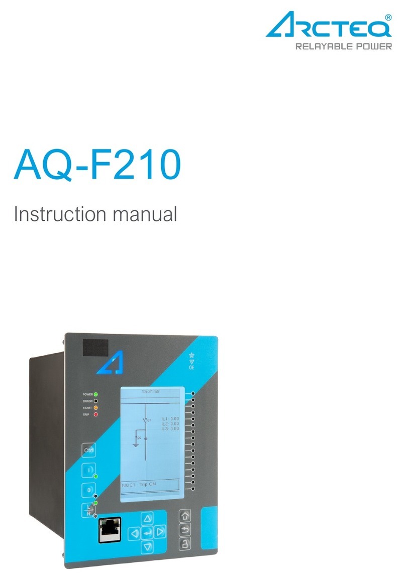
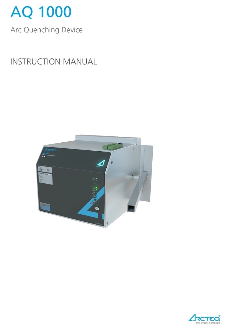
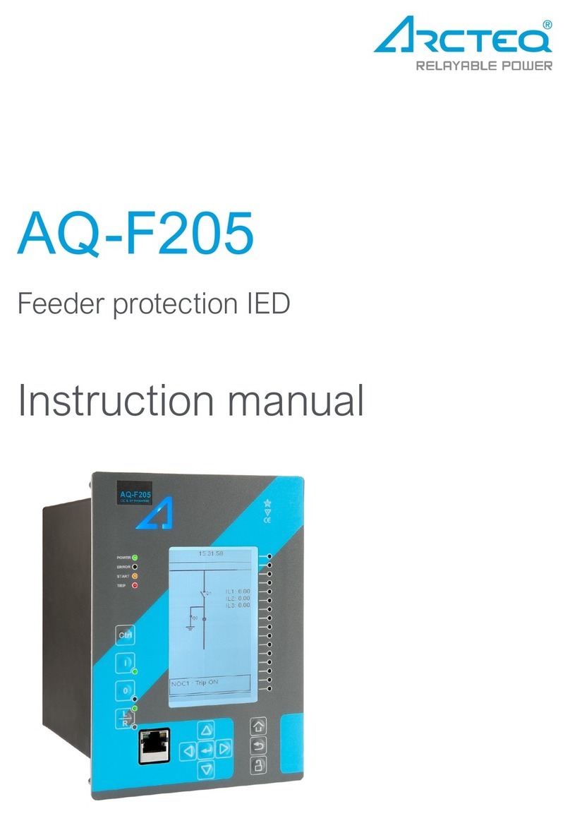
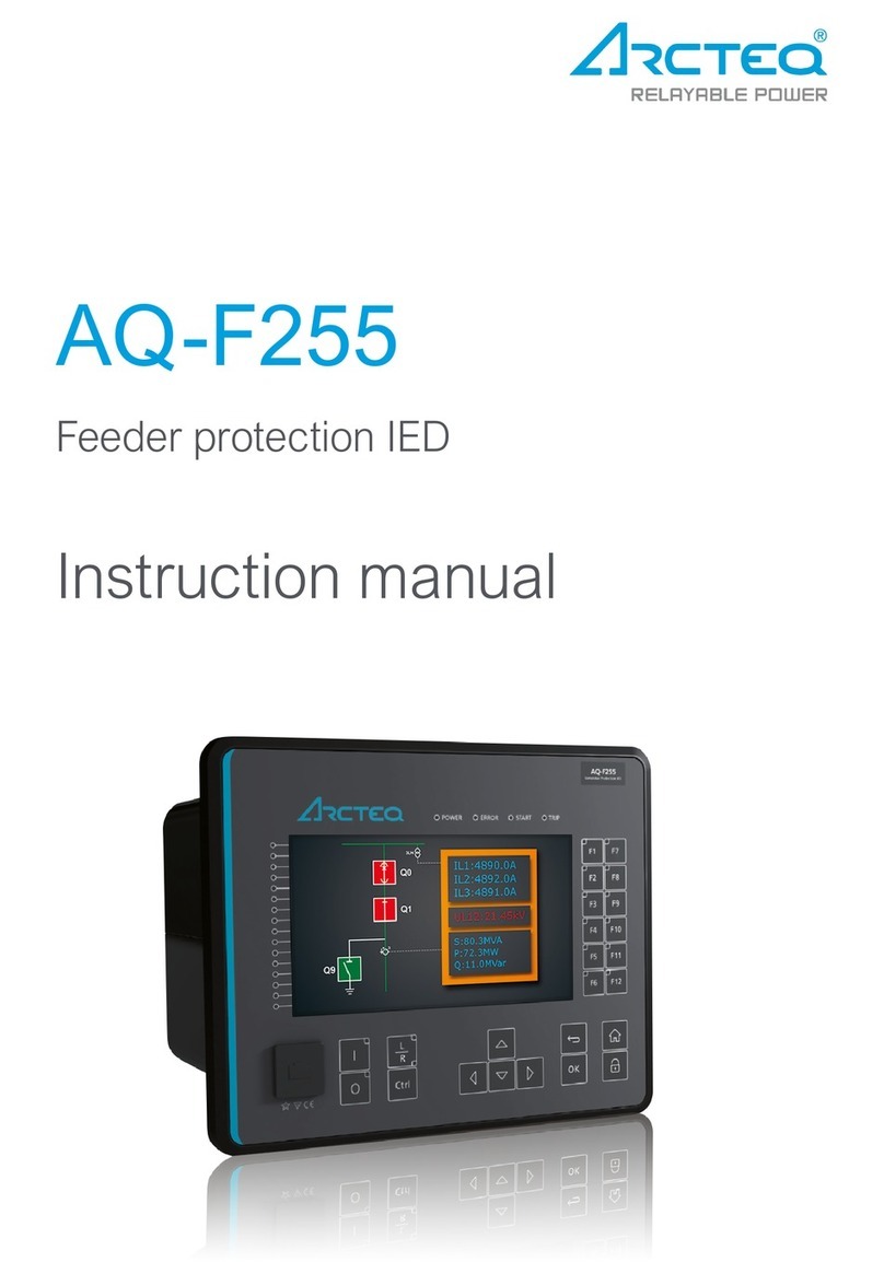
Arcteq AQ F205 User manual

INSTRUCTION MANUAL
AQ F205 –Feeder Protection Relay

Instuction manual –AQ F205 Feeder protection IED 2 (404)
Revision
1.00
Date
8.4.2013
Changes
-The first revision for AQ-F205 IED.
Revision
1.01
Date
22.11.2013
Changes
-Application example for ARON input connection added
-Application example for trip circuit supervision.
-Added power protection functions.
-Added over- and underfrequency protection description and
technical data.
Revision
1.02
Date
16.9.2014
Changes
-Added df/dt and synchrocheck function.
Revision
1.03
Date
20.1.2014
Changes
-Added system integration text: SPA protocol.
Read these instructions carefully and inspect the equipment to become familiar with it
before trying to install, operate, service or maintain it.
Electrical equipment should be installed, operated, serviced, and maintained only by
qualified personnel. Local safety regulations should be followed. No responsibility is
assumed by Arcteq for any consequences arising out of the use of this material.
We reserve right to changes without further notice.

Instuction manual –AQ F205 Feeder protection IED 3 (404)
TABLE OF CONTENTS
1ABBREVIATIONS ............................................................................................................. 6
2GENERAL......................................................................................................................... 7
3IED USER INTERFACE .................................................................................................... 8
3.1 AQ 200 series local panel structure........................................................................ 8
3.2 IED programming.......................................................................................... 8
3.2.1 Basic configuration ....................................................................................... 8
3.2.2 Navigation in main configuration menus...................................................... 10
4FUNCTIONS OF AQ-F205 FEEDER PROTECTION IED................................................ 38
4.1 Measurements ..................................................................................................... 39
4.1.1 Current measurement and scaling .............................................................. 39
4.1.2 Voltage measurement and scaling.............................................................. 53
4.1.3 Frequency tracking and sampling ............................................................... 64
4.1.4 Power and energy calculation ..................................................................... 67
4.2 Protection functions ............................................................................................. 75
4.2.1 General properties of a protection function ................................................. 75
4.2.2 Non-directional over current I> (50/51)........................................................ 88
4.2.3 Non-directional earth fault I0> (50N/51N).................................................... 95
4.2.4 Directional over current IDir> (67) ............................................................. 101
4.2.5 Directional earth fault I0Dir> (67N)............................................................ 110
4.2.6 Current unbalance I2> (46) ....................................................................... 120
4.2.7 Harmonic over current IH> (50H/51H/68H) ............................................... 127
4.2.8 Circuit breaker failure protection (CBFP) (50BF)....................................... 135
4.2.9 Restricted earth fault / cable end differential (REF) I0D> (87N)................. 148
4.2.10 Thermal overload protection for feeders TF> (49F).................................... 156
4.2.12 Over voltage U> (59) ................................................................................ 175
4.2.13 Under voltage U< (27)............................................................................... 181
4.2.14 Sequence voltage protection U1>/< or U2>/< (59P/27P/47/59N) .............. 187
4.2.15 Negative sequence over voltage U2> (59N/47)......................................... 195
4.2.16 Neutral voltage U0> (59N) ........................................................................ 209
4.2.17 Over power P> (32O)................................................................................ 217
4.2.18 Under power P< (32U).............................................................................. 221
4.2.19 Reverse power Pr (32R) ........................................................................... 228
4.2.20 Over- and under frequency f>/< (81O/81U)............................................... 233
4.2.21 Rate-of-change of frequency protection df/dt (81R) .................................. 238
4.3 Control functions................................................................................................ 245

Instuction manual –AQ F205 Feeder protection IED 4 (404)
4.3.1 Setting group selection (SGS)................................................................... 245
4.3.2 Object control and monitoring (OBJ) ......................................................... 253
4.3.3 Auto-reclosing 0 1 (79) ......................................................................... 262
4.3.4 Cold load pick-up (CLPU) ......................................................................... 291
4.3.5 Switch on to fault (SOTF).......................................................................... 299
4.3.1 Synchrocheck function ΔV/Δa/Δf (25) ....................................................... 301
4.4 Monitoring functions........................................................................................... 311
4.4.1 Current transformer supervision (CTS) ..................................................... 311
4.4.2 Disturbance recorder (DR)........................................................................ 321
4.4.3 Measurement recorder.............................................................................. 331
4.4.4 Circuit breaker wear -monitor (CBW) ........................................................ 332
4.4.5 Total harmonic distortion monitor (THD) ................................................... 338
5SYSTEM INTEGRATION .............................................................................................. 344
5.1 Communication protocols................................................................................... 344
5.1.1 NTP .......................................................................................................... 344
5.1.2 ModbusTCP and ModbusRTU .................................................................. 345
5.1.3 ModbusIO ................................................................................................. 346
5.1.4 IEC 103..................................................................................................... 347
5.1.5 SPA protocol............................................................................................. 347
6CONNECTIONS............................................................................................................ 348
7CONSTRUCTION AND INSTALLATION....................................................................... 350
7.1 CPU, IO and Power supply module.................................................................... 351
7.2 Current measurement module............................................................................ 353
7.3 Voltage measurement module ........................................................................... 354
7.4 Digital input module DI8..................................................................................... 355
7.5 Digital output module DO5................................................................................. 356
7.6 Installation and dimensions................................................................................ 357
8APPLICATIONS ............................................................................................................ 360
8.1 3LN+U0 connection example............................................................................. 360
8.2 3-phase, 3-wire ARON input connection example.............................................. 361
8.3 Trip circuit supervision ....................................................................................... 362
8.3.1 Trip circuit open coil supervision with one digital input and connected trip
output .............................................................................................................. 362
8.3.2 Trip circuit open coil supervision with one digital input and connected and
latched trip output............................................................................................ 364
9TECHNICAL DATA ....................................................................................................... 366
9.1 Connections....................................................................................................... 366
9.1.1 Measurements.......................................................................................... 366
Instuction manual –AQ F205 Feeder protection IED 5 (404)
9.1.2 Auxiliary voltage........................................................................................ 369
9.1.3 Binary inputs............................................................................................. 369
9.1.4 Binary outputs........................................................................................... 370
9.1.5 Communication ports................................................................................ 370
9.2 Protection functions ........................................................................................... 372
9.2.1 Current protection functions ...................................................................... 372
9.2.2 Voltage protection functions...................................................................... 381
9.2.3 Power protection functions........................................................................ 384
9.2.4 Frequency protection functions ................................................................. 384
9.3 Control functions............................................................................................... 387
9.4 Monitoring functions........................................................................................... 392
9.5 Tests and environmental.................................................................................... 396
9.5.1 Electrical environment compatibility .......................................................... 396
9.5.2 Physical environment compatibility ........................................................... 397
9.5.3 Casing and package ................................................................................. 397
10 ORDERING INFORMATION ......................................................................................... 398
11 APPENDIX.................................................................................................................... 399
12 REFERENCE INFORMATION ...................................................................................... 404

Instuction manual –AQ F205 Feeder protection IED 6 (404)
1ABBREVIATIONS
CB –Circuit breaker
CBFP –Circuit breaker failure protection
CT –Current transformer
CPU –Central processing unit
EMC –Electromagnetic compatibility
HMI –Human machine interface
HW –Hardware
IED –Intelligent electronic device
IO –Input output
LED –Light emitting diode
LV –Low voltage
MV –Medium voltage
NC –Normally closed
NO –Normally open
RMS –Root mean square
SF –System failure
TMS –Time multiplier setting
TRMS –True root mean square
VAC –Voltage alternating current
VDC –Voltage direct current
SW –Software
uP - Microprocessor

Instuction manual –AQ F205 Feeder protection IED 7 (404)
2GENERAL
The AQ-F205 Feeder Protection IED is a member of the AQ-200 product line. The AQ-200
protection product line in respect of hardware and software is a modular concept. The
hardware modules are assembled and configured according to the application IO
requirements and the software determines the available functions. This manual describes
the specific application of the AQ-F205 Feeder Protection IED. For other AQ-200 series
products please consult corresponding device manuals.

Instuction manual –AQ F205 Feeder protection IED 8 (404)
3IED USER INTERFACE
AQ 200 series IED user interface section is divided into hardware- and software user
interface sections. Software interface is divided into local panel configuration and
programming by using AQtivate 200 freeware software suite.
3.1 AQ 200 SERIES LOCAL PANEL STRUCTURE
AQ 200 series IED have multiple LEDs, control buttons and local RJ-45 Ethernet port for
configuration on front as a default. On rear each unit is equipped with RS-485 serial
interface and RJ-45 Ethernet interface options as a standard. See list below.
4 default LEDs for free configuration: Power,
Error, Start and Trip.
16 freely configurable LEDs with
programmable legend texts.
3 object control buttons: Choose the
controllable object with Ctrl –button, control
breaker with 0- and I push buttons.
L/R push button for local remote control.
7 Navigation buttons for IED local
programming and a button for password
activation.
RJ-45 Ethernet port for IED configuration.
Figure 3.1-1 AQ-200 series IED local panel structure.
3.2 IED PROGRAMMING
3.2.1 BASIC CONFIGURATION
IED user interface is divided into 5 quick displays. The displays are Events, Favorites,
Mimic, LEDs and Clock. Default quick display is the mimic view and it is possible to glance
through these menus by pressing arrows left and right. Home button transfers the user
between quick displays and 6 main configuration menus. Main configuration menus are

Instuction manual –AQ F205 Feeder protection IED 9 (404)
General, Protection, Control, Communication, Measurements and Monitoring. You can
choose the main menu by using the four arrow keys and press enter.
Figure 3.2.1-2 AQ-200 series IED basic navigation.
Moving around in the five main quick displays is done by pressing navigation keys
to left and right “ ”.
Home button “ ” transfers the user between the quick displays and six main
configuration menus.
Moving around in main configuration menus is done by pressing navigation buttons
“ ” and entering menu is confirmed by pressing enter “
”. Notice that name of the main menu appears to the bottom of the display while
staying on top of icon.

Instuction manual –AQ F205 Feeder protection IED 10 (404)
Cancel key “ ” takes you one step back or holding it down for 3 seconds takes
you back to general –menu “ ”.Cancel key is also used for alarm LEDs reset.
Padlock button “ ” takes user to password menu where it is possible to enter
different user levels (user, operator, configurator and super user).
3.2.2 NAVIGATION IN MAIN CONFIGURATION MENUS
All the settings in AQ-200 series IEDs have been divided into six main configuration menus.
Main configuration menus are presented below.
Figure 3.2.2-3 AQ-200 series IED main configuration menus.

Instuction manual –AQ F205 Feeder protection IED 11 (404)
3.2.2.1 GENERAL MENU
General menu “ ” includes Device Info- and Function Comments sub-menus.
DEVICE INFO
Set name and location of the device.
Serial number and SW version of the IED.
Hardware configuration (order code).
Source for time synchronization, Internal or
External (internal as default).
Enable stage forcing (disabled / enabled).
When forcing is disabled after using every
forced output will restore. Forcing is done
individually in info menu of each stage.
Language selection, all available languages
here (English as default).
Clear devices events.
LCD contrast level and setting 0…255 (120
as default).
Reset latched signals
Protection/Control/Monitor profile: Status of
enabled stages.
Figure 3.2.2.1-4 AQ-200 series IED Device Info sub- menu.

Instuction manual –AQ F205 Feeder protection IED 12 (404)
FUNCTION COMMENTS
Set specific note to protection stage or
object. Note is visible under Info –menu of
each stage.
Figure 3.2.2.1-5 AQ-200 series IED Function Comments sub- menu.

Instuction manual –AQ F205 Feeder protection IED 13 (404)
3.2.2.2 PROTECTION MENU
Protection menu “ ” includes Stage activation sub-menu and sub-menus for different
protection functions like Overcurrent, Earthfault, Seq. and balance and Supporting. Valid
protection functions vary according IED type.
Figure 3.2.2.2-6 AQ-200 series IED Protection menu view. Protection stages vary
according IED type.

Instuction manual –AQ F205 Feeder protection IED 14 (404)
STAGE ACTIVATION
Activation of different protection stages is
done in Stage activation –sub menu. Each
protection stage and supporting function is
disabled as standard.
Activated menus will appear below the stage
specific sub-menu for example I> appears
below Current –module, U< appears below
Voltage-module etc.
Figure 3.2.2.2-7 AQ-200 series IED Stage activation sub- menu.
EXAMPLE PROTECTION STAGE
Figure 3.2.2.2-8 AQ-200 series IED stage navigation and modification.
Each protection stage and supportive function has five stage menus Info, Settings,
Registers, IO and Events.

Instuction manual –AQ F205 Feeder protection IED 15 (404)
Function is activated and disabled in Stage
activation menu. It is possible to disable
function in Info menu as well.
Function condition indicates whether the
stages condition is Normal, Start or Trip.
Measured amplitude can be Peak-to-peak,
TRMS or RMS. As a default it is set as RMS.
Under Characteristic graphs-title you can
open graphs related to the protection
function.
Info view has calculator for function starts,
trips and blockings. It is possible to clear
calculators by choosing Clear statistics and
Clear.
Measurements are visible in Info menu.
Active setting group and its settings are all
visible in Info menu.
Figure 3.2.2.2-9 Info menu indicates all the details listed below certain protection stage or
function.

Instuction manual –AQ F205 Feeder protection IED 16 (404)
Figure 3.2.2.2-10 All group specific settings are done individually in Settings menu.
Stage settings vary according different protection functions. With factory settings only one
group of eight is activated. To enable more groups go to Control menu and select Setting
Groups.

Instuction manual –AQ F205 Feeder protection IED 17 (404)
Figure 3.2.2.2-11 AQ-200 series IED stage information is divided into two sections.
Specific fault data of IEDs is stored in operation log under the register. Each of these 12
logs includes pre-fault current, fault current, time stamp and active group during the
triggering. Operation log can be cleared by choosing Clear registers Clear.
Events generated by the specific stage can be checked by going to Stage event register.
General events cannot be cleared.

Instuction manual –AQ F205 Feeder protection IED 18 (404)
Figure 3.2.2.2-12 AQ-200 series IED stage information is divided into two sections.
Starting and tripping signals of protection stages are connected to physical outputs in Direct
Output Control menu. It is possible to connect to output relay or to start- trip- or user
configurable LED. In case when stage is internally blocked (DI or other signal) it is possible
to configure an output to indicate that stage is blocked. Connection to outputs can be either
latched |x| or non-latched x.
Stage blocking is done in Blocking Input Control menu. Blocking can be done by using
digital inputs, logical inputs or outputs, stage start- trip- or blocked information or by using
object status information.

Instuction manual –AQ F205 Feeder protection IED 19 (404)
Figure 3.2.2.2-13 Protection stage related events are masked on and off individually under
EventsEvent mask.
Events are masked off as default. It is possible to activate desired events by masking them
|x|. Only masked events appear to event list. Events cannot be cleared.
3.2.2.3 CONTROL MENU
Control menu “ ” includes Controls Enabled sub-menu and sub-menus for different
control functions like Setting Groups, Objects, Control Functions and Device IO. Valid
control functions vary according IED type.
Figure 3.2.2.3-14 AQ-200 series IED Control menu view. Functions vary according IED
type.

Instuction manual –AQ F205 Feeder protection IED 20 (404)
CONTROLS ENABLED
Activation of different control functions is
done in Controls Enabled –sub menu. Each
control function is disabled as standard.
Active functions will appear below Control
Functions –sub menu.
Activated objects will appear below Objects –
sub menu. Each object is disabled as
standard.
Figure 3.2.2.3-15 AQ-200 series IED Controls Enabled sub- menu.
SETTING GROUPS
Active setting group displays the current
active setting group 1…8.
It is possible to activate desired setting group
by setting the force SG. While doing this
Force SG change has to be enabled.
In Used setting groups menus it is possible
to activate setting groups between 1 and
1…8 (default only 1 group is active).
Select local control for different setting
groups from SG Local Select. Digital inputs,
Logical inputs or outputs, stage starting-
tripping- or blocking, RTDs and object status
information can be used.
Event masking for setting groups (masks are
off as default). Only masked events appear
to event list. Events cannot be cleared.
Figure 3.2.2.3-16 Setting Groups menu displays all the information related to group
changing.
Setting group 1 has the highest and group 8 the lowest priority. Setting groups can be
controlled with steady signal or pulses.
Other manuals for AQ F205
3
Table of contents
Other Arcteq Relay manuals

Arcteq
Arcteq AQ-T257 User manual

Arcteq
Arcteq AQ-F255 User manual

Arcteq
Arcteq AQ 1000 User manual

Arcteq
Arcteq AQ-R215 User manual

Arcteq
Arcteq AQ F205 User manual

Arcteq
Arcteq AQ-F201 User manual

Arcteq
Arcteq AQ-F201 User manual

Arcteq
Arcteq AQ-F201 User manual

Arcteq
Arcteq AQ-F210 User manual

Arcteq
Arcteq AQ-S215 User manual