Arcteq AQ 1000 User manual

AQ 1000
Arc Quenching Device
INSTRUCTION MANUAL

AQ-1000 Instruction Manual - 1.3 EN.docx Page | 2
© Arcteq ltd
Revision History
Revision
v 1.1
Date
22.06.2016
Changes
Table of contents corrected
Revision
v 1.2
Date
03.04.2017
Changes
Technical data updated.
Revision
v 1.3
Date
04.10.2018
Changes
Technical data updated, connections updated, layout updated.

AQ-1000 Instruction Manual - 1.3 EN.docx Page | 3
© Arcteq ltd
Disclaimer
Read these instructions carefully before performing any kind of installation, operation, service or maintenance to equipment described in this
document. This document is not intended as an instruction manual for untrained persons.
Product described in this document should be installed, operated, serviced, and maintained only by qualified personnel and entities.
It is the sole responsibility of the person or entity responsible to ensure a secure environment and to take the necessary measures including e.g.
authentication, encryption, anti-virus programs, safe switching programs and similar actions necessary to ensure safe environment and usability
for this product. Arcteq is not liable for any such damages and/or losses related to possible defects described above.
Local legislation and regulations always must be followed, regardless of the content of this document. This document has been reviewed by
Arcteq Relays Ltd. but deviations cannot be ruled out. In case of any errors detected, the reader should notify the manufacturer.
No any kind of responsibility is assumed by Arcteq Relays Ltd. for any consequences arising out of the use of this material.
We reserve right to changes without further notice.
Copyright
Copyright © Arcteq Relays Ltd. 2018. All rights reserved.

AQ-1000 Instruction Manual - 1.3 EN.docx Page | 4
© Arcteq ltd
Table of Contents
Disclaimer.................................................................................................................................................................................. 3
Copyright.................................................................................................................................................................................. 3
1 Safety Precautions................................................................................................................................................................... 5
2 Installation.............................................................................................................................................................................. 6
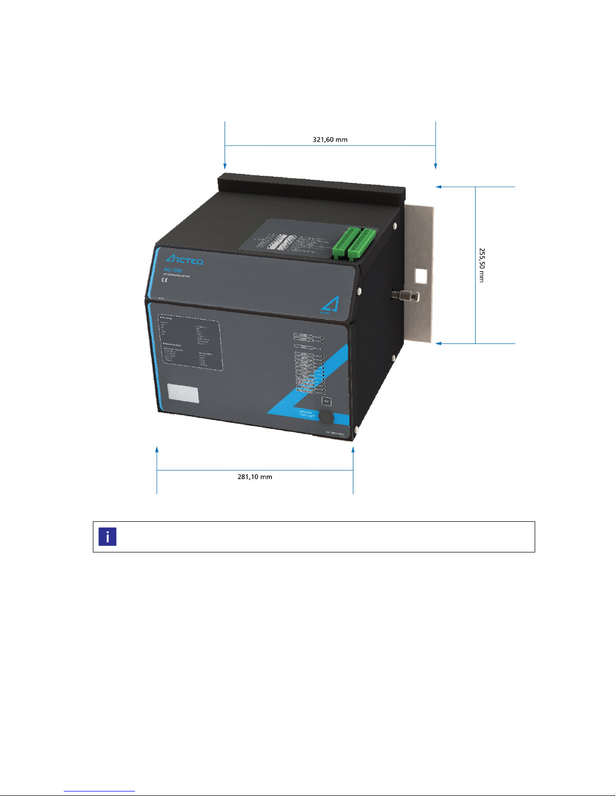
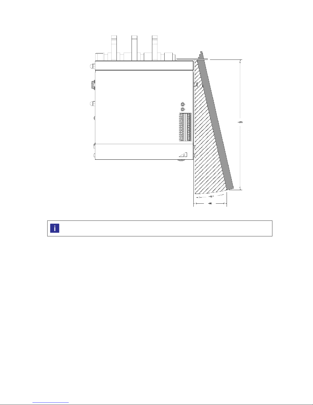
2.1 Device dimensions ......................................................................................................................................................... 6
2.2 Mechanical installation................................................................................................................................................. 12
2.3 Wiring......................................................................................................................................................................... 15
2.4 Device Grounding........................................................................................................................................................ 16
3 Operation............................................................................................................................................................................. 17
3.1 Operating modes......................................................................................................................................................... 17
3.2 LED Indicators.............................................................................................................................................................. 18
3.3 Binary Input Functions ................................................................................................................................................. 19
3.4 SET Button .................................................................................................................................................................. 19
3.4 Self-supervision functions............................................................................................................................................. 19
3.5 Restoring quenching device contacts ............................................................................................................................ 20
4 Commissioning..................................................................................................................................................................... 21
5 Application Example ............................................................................................................................................................. 22
6 Technical data ...................................................................................................................................................................... 24
7 Order Code .......................................................................................................................................................................... 27
Contact information ................................................................................................................................................................ 28

AQ-1000 Instruction Manual - 1.3 EN.docx Page | 5
© Arcteq ltd
1 Safety Precautions
AQ1000 arc quenching device is intended for making low-impedance short circuit between all
the phases and ground, which is comparable to bolted short circuit to ground.
Installation shall not be done before the entire system has been verified to withstand bolted short
circuit. This verification shall include, but not limited to:
•Source transformers and generators
•PT’s, CT’s, VT’s
•Circuit breakers
•Busbars and cables
•Busbar insulators and supports
•Switchgear structure
During tripping, equipment can exceed noise level 85 dB(A). Wearing of hearing protection, is
recommended when making commissioning tests or when operating with the device.
Before installation, it shall be verified that there is no intentional live feed or un-intentional back
feed to the busbars.
Read these instructions carefully and inspect the equipment to become familiar with it before
trying to install, operate, service or maintain it. Electrical equipment should be installed,
operated, serviced, and maintained only by qualified personnel. Local safety regulations should
be followed. No responsibility is assumed by Arcteq for any consequences arising out of the use
of this material. We reserve right to changes without further notice.
Device should not be removed, or any other service works done when the energy storage
component is charged. See chapter 3.1 Operating modes for more information regarding
operation.

AQ-1000 Instruction Manual - 1.3 EN.docx Page | 6
© Arcteq ltd
2 Installation
2.1 Device dimensions
Figure 2-1: Device total widths. All dimensions in millimeters.
See installation and mounting related technical instructions in chapter 6 Technical data.

AQ-1000 Instruction Manual - 1.3 EN.docx Page | 7
© Arcteq ltd
Figure 2-2: Device dimensions from front. All dimensions in millimeters.
See installation and mounting related technical instructions in chapter 6 Technical data.

AQ-1000 Instruction Manual - 1.3 EN.docx Page | 8
© Arcteq ltd
Figure 2-2: Device dimensions from left side. All dimensions in millimeters.
See installation and mounting related technical instructions in chapter 6 Technical data.

AQ-1000 Instruction Manual - 1.3 EN.docx Page | 9
© Arcteq ltd
Figure 2-3: Reset handle movement area and space reservation. All dimensions in millimeters.
See installation and mounting related technical instructions in chapter 6 Technical data.

AQ-1000 Instruction Manual - 1.3 EN.docx Page | 10
© Arcteq ltd
Figure 2-4: Mounting dimensions from bottom side. All dimensions in millimeters.
See installation and mounting related technical instructions in chapter 6 Technical data.

AQ-1000 Instruction Manual - 1.3 EN.docx Page | 11
© Arcteq ltd
Figure 2-5: Busbar joint dimensions form back side. All dimensions in millimeters.
See installation and mounting related technical instructions in chapter 6 Technical data.

AQ-1000 Instruction Manual - 1.3 EN.docx Page | 12
© Arcteq ltd
2.2 Mechanical installation
Figure 2-6: Installation picture – tray assembly.
See installation and mounting related technical instructions in chapter 6 Technical data.

AQ-1000 Instruction Manual - 1.3 EN.docx Page | 13
© Arcteq ltd
Figure 2-7: Installation picture – C-rail assembly.
See installation and mounting related technical instructions in chapter 6 Technical data.

AQ-1000 Instruction Manual - 1.3 EN.docx Page | 14
© Arcteq ltd
Figure 2-8: Installation picture – bus bar mounting alternatives.
See installation and mounting related technical instructions in chapter 6 Technical data.
Busbar sizing and clearance distances shall be dimensioned according to switchgear ratings and maximum short circuit
current.

AQ-1000 Instruction Manual - 1.3 EN.docx Page | 15
© Arcteq ltd
2.3 Wiring
Function
Function
- Binary input 1 – Clear Self-supervision – Closed; System alarm
+ Binary input 1 – Clear Self-supervision – Common
- Binary input 2 – Commissioning mode Self-supervision – Closed; System healthy
+ Binary input 2 – Commissioning mode
Maintenance alarm – Closed; Maintenance needed
Not in use
Maintenance alarm - Common
Not in use
Device Ready – Closed; Device not ready
- Binary input 4 – Blocking function
Device Ready – Common
+ Binary input 4 – Blocking function
Device Ready – Closed; Device is ready
Not in use
Operation Blocked - Closed; Device operation blocked
Not in use
Operation Blocked - Common
Not in use
Operation Blocked – Closed; Device unblocked
Not in use
Trip contact
Not in use
Trip contact
Not in use
+ Auxiliary Supply (Option A: 80-265V AC / DC, Option B: 17-82 DC)
Not in use
- Auxiliary Supply (Option A: 80-265V AC / DC, Option B: 17-82 DC)
Function
COM 1 – Fiber connector; Trip In
See rated voltages, wire sizing and connector tightening torques in chapter 6 Technical data.
Device electronics contains no separate grounding wire connector. Electronics are grounded to the device chassis. See
chapter 2.4 Device Grounding for more information.

AQ-1000 Instruction Manual - 1.3 EN.docx Page | 16
© Arcteq ltd
2.4 Device Grounding
The grounding of the device is connected to the device chassis. When grounding the AQ1000 device, attention shall be paid for verifying
adequate grounding is existing in switchgear.
This grounding connection can be used when grounding was found inadequate.

AQ-1000 Instruction Manual - 1.3 EN.docx Page | 17
© Arcteq ltd
3 Operation
AQ1000 contains no user settable or application dependent parameters or values.
3.1 Operating modes
Mode
Definition
Charging
In charging mode, the device charges the energy storage with sufficient energy to move the contacts to the closed
position. During normal operation, the charging occurs several times in hour as the charged energy level is constantly
monitored and adjusted. During charging, the indication LED in the front panel is on.
Ready
In ready mode, the device’s energy storage is charged to sufficient energy level and device is ready to operate.
Trip
In trip state, the device has operated, and energy storage is empty. In trip mode, the LED indicators are showing trip
and closed state.
Blocked
Blocked mode occurs when the binary input 4 is energized. During blocking the movement of quenching contacts is
prevented.
Discharging
Discharging mode occurs when the device auxiliary power is disconnected. In discharging mode, the energy storage is
safely discharged. LED indicator is showing the discharging mode until safe voltage level is reached and indicator turns
off. Refer to chapter 6 Technical data for discharging time specification.
Commissioning
When performing commissioning or periodical testing commissioning mode is recommended to be activated by
energizing binary input 2. In commissioning mode, device internal operation counter is blocked.
(When allowed maximum number of operations is reached maintenance alarm is activated automatically. User should
contact Arcteq technical support when maintenance alarm is constantly active and binary input 2 is de-energized.)
Maintenance Contac Arcteq technical support for further instructions.
Figure 3-1: Operating modes ready and trip.

AQ-1000 Instruction Manual - 1.3 EN.docx Page | 18
© Arcteq ltd
3.2 LED Indicators
AQ1000 contains LED indicators for operating states as per the following:
LED
Color
OFF
Steady ON
Blinking
Power Blue
Auxiliary supply
disconnected
Auxiliary power
connected
Internal voltage error
Error
Red
System healthy
System unhealthy
N/A
Trip
Red
Device not tripped
Device tripped
N/A
Ready
Green
Device not ready to trip
Device ready to trip
N/A
Open
Green
Contact not open
Contact open
Error position
Closed
Red
Contact not closed
Contact closed
Error position
Charging Orange Device not charging
Device is charging the
energy storage
Charging error
COM 1 Green N/A
Fiber connection
healthy
Fiber connection lost
COM 2 Green N/A
Fiber connection
healthy
Fiber connection lost
Clear
Green
Clear input inactive
Clear input active
N/A
Commissioning Orange N/A N/A
Device is in
commissioning mode
Maintenance Orange N/A N/A
Maintenance needed,
contact manufacturer
Blocked
Red
N/A
N/A
Blocked input active
Discharging Orange N/A
Device is discharging
the energy storage
N/A
When error LED is active, refer to above table for troubleshooting.
Self-recovered error is indicated by blinking LED with error LED inactive.

AQ-1000 Instruction Manual - 1.3 EN.docx Page | 19
© Arcteq ltd
3.3 Binary Input Functions
Input
Function
BI1 - Clear input
Clear / reset the indications after error or trip event.
BI2 - Maintenance
In maintenance mode device internal operation counter is blocked.
-
Not used. (Reserved for future purposes.)
BI4 - Block input
Blocks the trip contact activation during commissioning or any other circumstances where the tripping shall be
prevented. See also chapter 4 Commissioning for using binary input 4 for testing / commissioning purposes.
3.4 SET Button
AQ1000 contains a SET button in the front panel, which is used for resetting the indicators after trip event and to clear the alarm signals.
Figure 3-2: SET button.
After the trip, restoring of quenching contacts to open position shall be done before pressing the SET button or
activating external clear signal by energizing binary input 1.
3.4 Self-supervision functions
Fiber connection lost:
When fiber connection is lost from either Com1 or Com2 port, error led turns ON and ready led turns OFF. Corresponding fiber led is blinking
(COM1 or COM2) indicating faulty connection channel. Simultaneously self-supervision contact changes status indicating system alarm.
After connection is restored, blinking COM led may be cleared by using the SET- button or clear input (BI1).
Temperature too low or high:
When temperature is out of device allowed temperature range (-10 C … +75 C) error led turns ON and ready led turns OFF. Simultaneously self-
supervision contact changes status indicating system alarm. After temperature returns to allowed range, device automatically switches to normal
state causing error led is switched OFF, ready led ON and self-Supervision contact changes status indicating system healthy.
Capacitor condition alarm:
In case device energy storage capacitance drops below 85% of nominal value maintenance mode is activated. User should contact Arcteq
technical support for further instructions.

AQ-1000 Instruction Manual - 1.3 EN.docx Page | 20
© Arcteq ltd
3.5 Restoring quenching device contacts
After arc flash incident restoring of arc protection system and quenching device must be done carefully and systematically.
Always follow equipment manufacturers and national instructions, safety policies and regulations.
Locate and remove the cause of fault.
•Restore quenching device contacts to open position by using the reset handle (see Figure 3-3: Reset of contacts.)
•Reset and clear indications of arc protection system with set buttons.
It is recommended to use the ready contact of AQ 1000 as lock out signal for the circuit breaker. This will prevent the
closed operation of the circuit breaker when the AQ1000 is in closed position or not ready to operate.
When a trip has occurred, the quenching contacts must be restored to the open position by using the handle provided with the device starting
from handle position 1. Device is reset, when shaft is moved to complete open position using handle position 3 and then pressing the clear
button. See figure below. Device indicates the open position with LED indicators.
Figure 3-3: Reset of contacts.
Remove the handle after reset. If not removed the handle may fly off from its slot in event of trip and cause harm or
damages.
Never attach the handle to device when shaft is in open position.
Other manuals for AQ 1000
1
Table of contents
Other Arcteq Relay manuals

Arcteq
Arcteq AQ-R215 User manual

Arcteq
Arcteq AQ-T257 User manual

Arcteq
Arcteq AQ-F201 User manual

Arcteq
Arcteq AQ-S215 User manual

Arcteq
Arcteq AQ-F201 User manual

Arcteq
Arcteq AQ-F210 User manual

Arcteq
Arcteq AQ-F201 User manual

Arcteq
Arcteq AQ-S254 User manual

Arcteq
Arcteq AQ-F255 User manual

Arcteq
Arcteq AQ F205 User manual
Popular Relay manuals by other brands

sprecher + schuh
sprecher + schuh CEP7-ED1 P Series Application and Installation

stürmann
stürmann HR-110 Product information

Pilz
Pilz PNOZ 8 operating manual

CHINT
CHINT NR2 Series User instruction

Simons Voss Technologies
Simons Voss Technologies SmartRelay user manual

VERIS INDUSTRIES, INC.
VERIS INDUSTRIES, INC. V102 installation guide