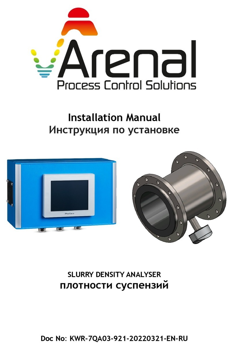
Arenal QA03-SDA Operating instructions

User Manual – Arenal PCS – QA03-SDA Page 1/74
User&MaintenanceMANUAL
SlurryDensityandSlurryMassflowAnalyzer/Easidens
DocNo:KWR-7QA03-901-220923-EN-C7E
ForSoftwareVersionKWR_7QA03_522_220902R

User Manual – Arenal PCS – QA03-SDA Page 2/74
Thank you for purchasing and using
Arenal's Slurry Density Analyzer for continuous monitoring of Specific
Gravity, Density, Total Suspended Solids, Water concentration in dry
tailings and temperature of mining, dredging, drilling and other slurries,
muds, pastes up to 5 kg/l, based on ultrasonic spectroscopy.
Since 2011, Arenal is the first and only producer in the world of ceramic
ultrasonic spectroscopy density and massflow analyzers. As the stability
and accuracy from 2021 is higher than nuclear analyzers, they will replace
most nuclear densitometers and also offer accurate monitoring under
water and in subsea mining applications. The technology is based on
measuring physical acoustical properties in combination of Acoustical
Spectroscopy of the slurry, which are, in a chemometry model, directly
related to the physical properties of the slurry, like slurry density, solids
concentration, water concentration and temperature. The temperature is
also measured by a separate PT1000 element.
For liquid density applications between 0.7<SG<1.4, we offer PEEK, PI,
Quartz and PBI sensors.
Due to continuous improvement of the software to comply with customer
requirements, the software changes rapidly and this manual is updated on
a continuous basis. If your software needs an update or upgrade, please
refer to the Maintenance & Support section 5 of this manual to support
you in your decision and to lead you through the updating or upgrading
procedure.
This manual is only valid for the software version on the front page.

User Manual – Arenal PCS – QA03-SDA Page 3/74
INDEX
1. Preface......................................................................................................................7
1.1 Our philosophy...........................................................................................................................7
1.2 Purpose of this manual...............................................................................................................7
1.3 Symbols and conventions...........................................................................................................7
1.4 Abbreviations .............................................................................................................................8
1.5 Document updates......................................................................................................................9
2. Technical specifications ......................................................................................... 10
2.1 Environmental characteristics ..................................................................................................10
2.2 Operation characteristics..........................................................................................................10
2.3 Dimensional drawing Rolec AC202 ........................................................................................ 11
2.4 Panel cut-out ............................................................................................................................12
2.5 Spare parts................................................................................................................................13
3. Installation............................................................................................................. 14
3.1 Generic configuration information...........................................................................................14
3.2 Mounting..................................................................................................................................14
3.3 Electrical cables installation.....................................................................................................15
3.4 Internal wiring..........................................................................................................................16
3.5 Connecting the QT0161-UDT .................................................................................................17
3.6 Connecting the QT656-TMT ...................................................................................................17
3.7 Connecting the QM132-IOM...................................................................................................17
4. Configuration......................................................................................................... 18
4.1 First time starting the system ...................................................................................................18
4.2 Menu structure .........................................................................................................................18
4.3 Menu screen and functions overview.......................................................................................18
4.4 Graph Setup Procedure ............................................................................................................21
4.4.1 Timing settings (horizontal X-axis)...................................................................................21
4.4.2 MIN/MAX setting (vertical Y-axis)....................................................................................21
4.4.3 Select the graphs of your choice on the screen .................................................................21
4.5 Configure Menu .......................................................................................................................22
4.5.1 Ultrasonic Density Transmitter Setup Procedure .............................................................22
4.5.2 IO Module Setup Procedure..............................................................................................22
4.5.3 System Settings Setup Procedure ......................................................................................22
4.5.4.1 User Settings ..................................................................................................................23
4.5.4.2 Factory Settings .............................................................................................................23
4.5.4.3 Restart system ................................................................................................................23

User Manual – Arenal PCS – QA03-SDA Page 4/74
4.5.4.4 Shutdown system ............................................................................................................23
4.6 Diagnose Menu ........................................................................................................................23
4.7 Alarm Menu .............................................................................................................................24
4.7.1 Active Alarm Handling Procedure ....................................................................................24
4.7.2 Screen warnings ................................................................................................................25
4.8 Help Menu................................................................................................................................25
4.9 Function bar .............................................................................................................................26
4.9.1 Ethernet Network ..............................................................................................................26
4.9.2 File Manager ....................................................................................................................27
4.9.3 Data Logging ....................................................................................................................27
4.9.4 Alarm.................................................................................................................................28
4.9.5 Take Sample ......................................................................................................................28
4.9.6 Security Level....................................................................................................................29
4.9.7 Screen Shot........................................................................................................................30
4.9.8 Save and Store Data on USB ............................................................................................30
4.10 Dredging – Reset Production .................................................................................................30
5. Start Up and Commissioning Guide....................................................................... 32
5.1 Check and unpack shipment ....................................................................................................32
5.2 Install the wafer, weldolet(s) or spoolpiece in the system .......................................................32
5.3 Install the analyzer on the desired location..............................................................................33
5.4 Mounting the C7E HMI ...........................................................................................................33
5.5 Connect the internal cables ......................................................................................................33
5.6 Connect the Massflow transmitter ...........................................................................................34
5.7 Power Up..................................................................................................................................35
5.8 Air and water calibration..........................................................................................................35
5.9 Slurry calibration......................................................................................................................36
5.10 Configure digital and analog outputs.....................................................................................40
6. Calculations .......................................................................................................... 41
6.1 Temperature..............................................................................................................................41
6.2 Density and SG calculation......................................................................................................41
6.3 TSS calculation ........................................................................................................................41
6.4 Flow calculation.......................................................................................................................42
6.5 Massflow calculation ...............................................................................................................42
7. QT01 – UDT (Ultrasonic Density Transmitter)........................................................ 43
7.1 General information .................................................................................................................43
7.2 Electrical connections ..............................................................................................................44
7.3 Advanced Setup .......................................................................................................................45
7.4.1 Echo ......................................................................................................................................45

User Manual – Arenal PCS – QA03-SDA Page 5/74
7.4.2 Measurements .......................................................................................................................46
7.4.3 Menu Bar: Calibration ..........................................................................................................46
7.4.4 Modbus RTU Settings...........................................................................................................47
7.4.5 Echo settings .........................................................................................................................47
7.4.6 Pulser settings .......................................................................................................................47
8. QM132‐IOM .......................................................................................................... 49
8.1 General information of the QM132-IOM ................................................................................49
8.2 Set-up .......................................................................................................................................50
8.2.1 Menu bar: mA IN Settings.................................................................................................50
8.2.2 Menu bar: mA OUT Settings.............................................................................................51
8.2.3 Menu bar: DI/DO..............................................................................................................51
8.2.4 Menu bar: Modbus RTU Communication.........................................................................52
8.3 Ground loops............................................................................................................................52
9. QM146‐RMM – Remote Monitoring Module........................................................ 54
10 TCP/IP Register ..................................................................................................... 55
10.1 Results of parameters .............................................................................................................55
11. Maintenance, Troubleshooting & Support .......................................................... 56
11.1 Arenal/C7E Software and firmware configuration ................................................................56
11.2 Updating Arenal Software......................................................................................................56
11.3 How to get Remote Support...................................................................................................58
11.3.1 QM146-RMM ..................................................................................................................58
11.3.2 VPN Remote Control .......................................................................................................58
11.3.3 AnyDesk...........................................................................................................................58
11.4 FAQ and Troubleshooting ......................................................................................................61
12 Warranty............................................................................................................... 62
12.1 Probes.....................................................................................................................................62
11.2 Transmitters............................................................................................................................62
11.3 Analyzers................................................................................................................................62
11.4 Performance of the application ..............................................................................................63
A1 Declaration of Conformity.................................................................................... 64
A2 Service support rates ........................................................................................... 65
A3 ISO‐9001:2008 certificate..................................................................................... 66
A4 Electrical diagram QA03‐SDA‐DIS‐VAC‐IOM‐UDT ................................................. 67
A5 Electrical diagram QA03‐SDA‐DIS‐VAC‐IOM‐XXX.................................................. 68
A6 Electrical diagram QA03‐SDA‐DIS‐VAC‐XXX‐UDT.................................................. 69
A7 Electrical diagram QA03‐SDA‐DIS‐VAC‐XXX‐XXX................................................... 70

User Manual – Arenal PCS – QA03-SDA Page 6/74
A8 Electrical diagram QA03‐SDA‐GPX‐VAC‐XXX‐IOM and QA03‐SMA‐GPT‐XXX‐IOM 71
A9 Electrical diagram QM102‐MPC‐HRT Remote Module......................................... 72
A10 Electrical diagram QT016(5) UDT (with QT65x TMT).......................................... 73
A11 Electrical diagram QT065x TMT.......................................................................... 74

User Manual – Arenal PCS – QA03-SDA Page 7/74
1.Preface
1.1 Our philosophy
Thank you for purchasing and using the slurry density and slurry massflow analyzer from Arenal PCS. Our
goal is to produce the most accurate ultrasonic and thermal sensors and transmitters on the market for
most demanding applications in all global markets. Secondly, we aim to give you the most comprehensive
calculations available for controlling most industrial processes, based on the measuring values in
combination with multi parameter calculations. As our PLC/HMI can be connected to any control valve or
other equipment, local processes can be fully automated with Arenal's Slurry Density and Massflow
Analyzer. For more sophisticated processing and HMI interaction, we advise to use the QA01 Process
Chemometry Analyzer.
Finally, Arenal has a philosophy for ongoing continuous improvement to suit most demanding applications
in the world. We hope that we can contribute eventually to all of your process systems on site.
Arenal aims to satisfy end users with regards to optimization and control of all their processes.
1.2 Purpose of this manual
This manual explains the installation, configuration, operation, calibration and maintenance of the Arenal
QA03 Slurry Density Analyzer and Slurry Massflow Analyzer, including probes, transmitters, modules and
cables.
1.3 Symbols and conventions
The following words and symbols indicate special messages:
Caution! This sign indicates that failure to follow directions could
result in damage to the equipment or loss of information.
Warning! This sign indicates that failure to follow directions in the
warning could result in bodily harm.
Important! This word indicates that the text that follows contains
clarifying information or specific instructions.

User Manual – Arenal PCS – QA03-SDA Page 8/74
Interesting! This word indicates that the text that follows contains
comments or interesting
points of information.
1.4 Abbreviations
All abbreviations in the manual are listed here.
QA03‐SDA
QA03‐SMA
Slurry Density Analyzer
Slurry Massflow Analyzer
QT016‐UDT Ultrasonic Density Transmitter. Electronic module to send high voltage pulses to
the probe and receives and analyses returning echo’s. The SDA and SMA
however further analyses these raw values and calculates the SG, Density, TSS
and temperature.
QP015‐UDP
QC000‐QQ
Ultrasonic Density Probe to determine Slurry Density
Connection cable between transmitters or modules to the SDA or SMA
QC014‐UDC Coaxial cable for harsh conditions in mining industry, to connect the UDP with
the UDT
QT656‐TMT Thermal Massflow Transmitter
QP654‐TMP Thermal Massflow Probe
QM132‐IOM
See Chapter 10: IO Module. An Extended IO Module, which offers galvanic
isolated mA inputs and outputs and digital inputs and outputs. The mA signals
have a sensitivity of 16 bits. The module is connected on the base motherboard.
SDA
SMA
See QA03‐SDA
See QA03‐SMA
UDT See QT014‐UDT
UDP See QP015‐UDP
UDC See QC014‐UDC
TMT See QT656‐TMT
TMP See QP654‐TMP
IOM See QM132‐IOM

User Manual – Arenal PCS – QA03-SDA Page 9/74
1.5 Document updates
Name
KWR‐7QA03‐901‐221007‐EN Revamp for C7E HMI screens
KWR‐7
Q
A03‐901‐220112‐EN
KWR‐7QA03‐901‐191218‐EN
Complete upgrade due to new displays, new software
Par.1.5 added to follow improvements in the document, according to our
ISO9001:2015
KWR‐7QA03‐901‐191203‐EN Calibration “Step 3”procedure modified in Par 7.3

User Manual – Arenal PCS – QA03-SDA Page 10/74
2.Technicalspecifications
2.1 Environmental characteristics
Ingress Protection QA03: IP65 (Limited due to touch screen display on front side. We recommend
mounting the analyzer inside a protective FRM or GRP cabinet)
QT0161: IP66. We recommend mounting the electronics NOT in direct sunlight.
QP015: IP68
Temperature Operating: 0‐50 degC
Storage: ‐10ºC to +60ºC
RH Relative humidity 10‐90% (non condensing)
Leakage protection Double NBR o‐ring and dual packing in case of QB021‐WDL
2.2 Operation characteristics
Interfaces Ethernet LAN RJ‐45 10Base‐T/100Base‐TX
USB2.0 type A
Modbus RTU over 2 wire RS485
Power 90‐263 Vac. 50‐60Hz Standard (select VAC model)
18‐32 Vdc Standard (select 24V model)
Consumption: 15W
Display 5,7” Color LCD soft touch screen display
256 colors, 320x240 pixels, 6MB FEPROM
Response time Sensor pulse repeat frequency: 0,001 seconds, averaged over 1 second. Updated
every second in the analyzer. Moving average can be set between 1‐60 seconds.
Measurement absolute
error
In tap water within calibrated temperature range: 3 g/l.
In slurry: average error is 9‐15 g/l, due to changing morphology of particles,
inhomogeneous state of slurry and temperature sensitivity of dissolved solids.
Measurement relative
error
15 g/l in the range 1000‐2500 g/l is 1%
Ageing About 1% per year. Perform a water calibration each 3 months.
Weight 2,5 kg
Dimensions Outside dimensions: 330x200 mm. Depth: 120 mm
Housing Aluminum die case with dry coating
Mounting Mounting holes available: just remove the aluminum panels, no need for opening
the lid of the enclosure

User Manual – Arenal PCS – QA03-SDA Page 11/74
2.3 Dimensional drawing Rolec AC202

User Manual – Arenal PCS – QA03-SDA Page 12/74
2.4 Panel cut‐out
In case the HMI is not mounted in Arenal’s standard enclosure, the HMI shall be mounted in another
enclosure to protect it against dust and water. Due to the lack of components on the market, Arenal offers
several HMI’s. Each has different panel cut outs. Find below the panel cut‐out specification of ProFace
GP4301‐TAD and GP4301‐TADW:
Length: 156 mm (6.14 in)
Hight: 123.5 mm (4.86 in)
Panel thickness 1.6...5 mm (0.06...0.2 in)
Radius in each corner: 3 mm (0.12 in) maximum
When installing the GP unit in a slanted position, the GP unit face should not incline more than 30°.
For easier maintenance, operation and improved ventilation, install the GP unit at least 100 mm (3.94 in.)
away from adjacent structures and other equipment as shown in the following illustration.

User Manual – Arenal PCS – QA03-SDA Page 13/74
2.5 Spare parts
Item Description
4-000-02 Spare fuse. One spare fuse is always supplied on the main PCB board. Fuse
medium dela
y
2,5A. Farnell 1354586, model 023402.5MXP, about 0,21 Euro
4-QA03-USB-16GB Spare industrial USB stick for QA03, 16 GB. Do not replace this USB stick
for a non-industrial USB stick, as they do not comply to the temperature
ran
g
es.
4-POWER CONVERTER 24V-
>24VDC 60W
Spare Power Converter for QT65 (24-24 vdc)
4-QA03-GP4301 Spare Displa
y
and IO set: GP4301TAD and QM132-IOM
4-QA03-GP4301TAD Spare Displa
y
and IO set: GP4301TAD and QM132-IOM
4-QA03-GP4301TADW Spare Displa
y
and IO set: GP4301TADW and QM132-IOM
4-QA03-LT4301TADAC Spare Displa
y
LT4301TADAC
4-QA03-PLC+DISPLAY Spare Complete set PLC and displa
y
. Displa
y
is removable
4-QA03-XT07CD-DE Spare Displa
y
and IO set: XT07CD-DE and QM132-IOM
4-QB021-393C-EPDM-1MM Spare EPDM 1mm packin
g
with inner rin
g
for SPC
4-QB021-393C-EPDM-2MM SpareEPDM 2mm packin
g
with inner rin
g
for SPC
4-QB021-393C-EPDM-3MM Spare EPDM 3mm packin
g
with inner rin
g
for SPC
4-QB021-350 Spare Wrench with handle L=100mm
4-QB021-354 Spare Saddle flan
g
e mountin
g
ass
y
for UDP-WFC probe
4-QB021-356 Spare Saddle flan
g
e mountin
g
ass
y
for TMP-SPC probe
4-QP015-UDP-SIC-LT Spare Ultrasonic Density Probe. Is only sold at the same time as the initial
order or onl
y
in combination with 4-QT0161-UDT-SPC
4-QT0161-UDT-SPC Spare UDT
4-QT65-PCB Spare Thermal Massflow Transmitter PCB board Rev3
4-
A
NTENN
A
-GSM-4G-600 Spare part - hi
g
h power antenna with RG58 to SM
A
4-O-RING-28X2 NBR Spare o-rin
g
for SPC sensor
4-O-RING-28X4 NBR Spare o-rin
g
for SPC sensor
4-O-RING-35X1.00 NBR Spare o-rin
g
for WFC assembl
y
4-O-RING-35X1.50 NBR Spare o-rin
g
for WFC assembl
y
4-O-RING-35X2.00 NBR Spare o-rin
g
for WFC assembl
y
4-O-RING-35X2.50 NBR Spare o-rin
g
for WFC assembl
y
4-O-RING-35X3.00 NBR Spare o-rin
g
for WFC assembl
y

User Manual – Arenal PCS – QA03-SDA Page 14/74
3.Installation
3.1 Generic configuration information
A complete Slurry Density Analyzer (SDA) and Slurry Massflow Analyzer (SMA) system comprises of the
following components:
1. QA03‐SDA or SMA. The analyzer can be separated into different parts, depending on the
requirements:
a) Housing
b) Power convertor
c) Main PCB board
d) IO Module
e) HMI
2. QT0161‐UDT – Ultrasonic Density Transmitter
3. QC013‐UDC ‐Coaxial cable, in case of QP015‐UDP probe, this item is included and not mentioned in
the list
4. QC000‐QQ‐01000‐XXX‐XXX Connection cable 100m from UDT to QA03
5. QP013‐UDP ‐Ultrasonic Density Probes for submersible applications
6. QP014‐UDP‐PRC – Small Ultrasonic Density Probe
7. QP015‐UDP – Ultrasonic Density Probes for mounting in spool pieces are wafer cells
8. QB03‐WFC – Wafer cell
9. QB05‐SWC – Steel wafer cell
10. QB06‐SPC – Spool Piece of carbon steel (QB06‐SPS is of Stainless Steel)
11. QS – Services: like Remote Monitoring Services, local service assistance, System Integration
Services, Spare Parts
12. When the massflow meter is supplied:
a) QT656‐TMT – Thermal Massflow Transmitter
b) QP654‐TMP – Thermal Massflow Probe
c) QC000‐QQ‐00100‐XXX‐XXX Connection cable from TMT to UDT
As the QA03‐SDA or SMA is the main part of every installation, where all settings are done and where all
information is gathered. Additional information, needed to set up the Ultrasonic Density Transmitters, can
be found in the enclosure of this manual.
3.2 Mounting
Arenal uses AluCase enclosure from Rolec Germany (www.rolec.de). To mount the enclosure to the wall, the
lid does not need to open. Just remove the aluminum panels on each side: they are clamped and easily
removable. Arenal supplies a mounting set in each delivery.

User Manual – Arenal PCS – QA03-SDA Page 15/74
Fix the enclosure to the backpanel by standard available screws, like M5x25 socket head cap screws, DIN
912.
3.3 Electrical cables installation
The QA03‐SDA is always supplied with four M20x1.5 threads for cable glands on the bottom side of the
enclosure. It has the following cable entries (from left to right):
1. Power supply cable gland
2. mA input (ext flow, density or level meter) and mA output cable gland
3. Modbus RTU cable to remote UDT transmitter
4. External RMM (Remote Monitoring Module)

User Manual – Arenal PCS – QA03-SDA Page 16/74
3.4 Internal wiring
The power AC/DC convertor is situated on the left side of the main board. In case of DC supply voltage, this
module is replaced by a DC/DC convertor. The fuses are just on the top‐right of it. The 24Vdc power output
of the power convertor is connected through the main board to the power supply of the HMI and the IO
Module. Also external transmitters are powered by this 24Vdc.
After opening the lid, the baseboard is visible.
On the left side, the power convertor is placed.
The IO module will be place in the middle.
The UDT is connected to the Modbus connector, see drawings in enclosures.
The RMM is connected to the PoE Ethernet adapter.
Below the special mainboard for customers in South Africa, supplied by our partner KRT Instruments.

User Manual – Arenal PCS – QA03-SDA Page 17/74
3.5 Connecting the QT0161‐UDT
Check Chapter 8 and drawings A1..A8 for the electrical connections on the main board. Connect these wires
to the corresponding connections (A+, B‐, 0Vdc, 24Vdc) on the UDT.
3.6 Connecting the QT656‐TMT
Check Chapter 9 to learn how to connect the TMT to the corresponding connections (A+, B‐, 0Vdc, 24Vdc)
on the spare connector of the UDT.
Connect the thick cables to the H Force and H GND. Connect the thin cables to their corresponding Sense (H
SenseP for H Force and H SenseN for H GND).
3.7 Connecting the QM132‐IOM
For information on how to connect and configure the mA in and out signals as well as digital inputs
and outputs, refer to chapter 10 or the installation manual.

User Manual – Arenal PCS – QA03-SDA Page 18/74
4.Configuration
4.1 First time starting the system
Only power the SDA when all cables are connected and the probe is
connected. Do not disconnect probes or transmitters when the system is
powered up, as many transmitters are not hot‐swappable.
Check again that the AC voltage is not connected to the 24Vdc connector
Once the unit is powered up, the lamp inside the SDA or SMA and UDT turns green and the lamp inside the
HMI turns red.
If a display is connected, it automatically comes into measurement and control mode. The display now
shows the measuring values. Wait for at least 15 minutes after start‐up if you wish to perform calibration.
For more information about calibration procedures, see chapter 4.
4.2 Menu structure
The menus can be reached by the Menu Bar on the top and the functions by the Function Bar on the
bottom. All these functions are explained in the next paragraphs. In this paragraph, you get an overview of
the most used required actions and the menu operation that is needed.
Some examples are given below. In the next subsections, the menus are explained in more detail.
Requirement 1st step 2nd step 3rd step 4th step
Change name of the Measuring
Site
Change date & Time & Language
Press:
In Menu Bar
Press
“System
Settings”
Press
“User Settings”
Change and save.
Change parameter settings and
calibrate
See Chapter 4
Check or change UDT settings or
calibrate raw measurement
values
Press:
In menu Bar
Press
“Ultrasonic
Density
Transmitter”
See Chapter 8
Check or change IO settings Press:
In menu Bar
Press
“IO Module”
See Chapter 10
4.3 Menu screen and functions overview
In this chapter, you find information about the generic hardware and software configuration, about how to
set up the analyzer and the parameters.

User Manual – Arenal PCS – QA03-SDA Page 19/74
MENU BAR →
Parameter values →
(example display)
FUNCTION BAR →
The picture above shows the main measurement screen. It consists of three parts: the MENU BAR on the
top is for navigation through all setup and information menu's. The FUNCTION BAR on the bottom is for
checking the status of important settings and offers special functions in specific menu's.
The middle the screen shows the four measurement parameters.
Press this button to go to the home screen (see picture above)
Press this button to go the graph screen, described in Par 3.4
Press this button to go the configuration screen, described in Par 3.5
Press this button to go the diagnose screen, described in Par 3.6
Press this button to go the alarm screen, described in Par 3.7
Press this button to go the information screen, described in Par 3.8
When pressing this icon you return to the previous viewed screen
Press this icon to get info how to set up the Ethernet network (IP address and Subnet Mask)
Press this button to go to the File Manager Menu and see if the USB is connected/recognized.
Press this button to configure the logging interval time and to start and stop logging.
Press this icon to change the intensity of the screen. Press the button again to close.
Press this icon when taking a sample. Press the button on the next screen so the system
registers in the logging file that a sample is taken for calibration.
This button shows the current status of the security level, normally 0. Press this button to log
in.
Press this button to make a screen shot. The jpg file can be found on the USB Stick in the
“ScreenCapture” directory.
Save all settings to the files on the USB Stick. This icon pops up when user gets into the
configuration pages.

User Manual – Arenal PCS – QA03-SDA Page 20/74
Go to the next page. In some cases, there is no following page: then it stays on this page or
returns to the main page where you originally came from.
To configure one of the four parameters, you can press the corresponding value button.
Furthermore, a warning can be shown on top of the start screen when the temperature is outside of the
calibration range. The warning will show “Outside Temperature Range”.
The minimum and maximum temperature for the calibration range can be found in the Calibration screen.
In the following example, a warning will show when the temperature is below 4.9 degrees or above 50.0
degrees. The system will continue operating, but measurements are less reliable when operating outside of
the calibration temperature range.
Other manuals for QA03-SDA
1
Table of contents
Other Arenal Measuring Instrument manuals
Popular Measuring Instrument manuals by other brands

Teledyne
Teledyne 3300TB operating instructions

Johnson
Johnson LDM85 Operator's manual

Keithley
Keithley 172 instruction manual

Rohm
Rohm F-SENSO CHUCK Quick start instructions

SENSIRION
SENSIRION SLF3 Series Operating guidelines

PCB Piezotronics
PCB Piezotronics IMI SENSORS 606B01/ICS-14 Installation and operating manual