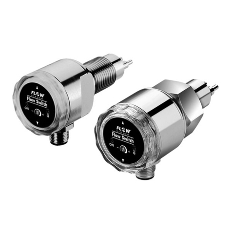
Flow vision FC100 - CA User manual

Flow Meter | FC100 - CA
USER MANUAL
M_FC100-CA_1121_e

GMBH
Flow Meter | FC100-CA
2
Equipment installation, connection and adjustment by qualified personnel only!
Important:
Please follow these instructions carefully. Failure to comply, or misuse of this equipment, could result
in serious damage both to the equipment itself and to the installation. FlowVision is unable to accept
responsibility for customer or third party liability, warranty claims or damage caused by incorrect
installation or improper handling resulting form non-observance of these instructions. All dimensions
are for reference only. In the interest of improved design, performance and cost-effectiveness the right
to make changes in these specifications without notice is reserved. Errors and omissions excepted.
The instructions cover firmware version 1.10.

FC100-CA | Flow Meter
GMBH
TABLE OF CONTENTS
3
Table of Contents
1 Description ..................................................... 6
1.1 Measuring procedure......................................................6
1.1.1 Calorimetric measuring procedure.....................................6
1.1.2 Physical principles of gas measurement . . . . . . . . . . . . . . . . . . . . . . . . . . . . . . . . 7
1.1.3 Standard and operating volume flow ...................................7
1.1.4 Measurements in compressed-air systems ..............................8
1.1.4.1 Consumption measurements .................................8
1.1.4.2 Leakage measurements .....................................8
1.2 System description........................................................9
1.2.1 User interfaces ...................................................10
2 Installation......................................................12
2.1 Installation of calorimetric monitoring heads...................................12
2.1.1 Selection of material...............................................12
2.1.2 Mechanical installation .............................................13
2.1.2.1 Thread-mounted monitoring head CST-11 ......................13
2.1.2.2 Insertion head CSP for sensor adapter TP- … or ball valve BV- … . . 14
2.1.2.3 Sensor adapter TP- … .....................................15
2.1.2.4 Ball valve BV- … ..........................................16
2.1.2.5 Push-in monitoring head CSF-11AM1/CSF-11AM2 ............... 17
2.1.3 Mounting instructions for monitoring head CST .........................18
2.1.3.1 Depth of immersion .......................................18
2.1.4
Mounting instructions for monitoring head CSP with sensor adapter TP or ball valve BV
19
2.1.5 Mounting instructions for push-in monitoring head CSF ...................19
2.1.5.1 Standard velocity profiles: ..................................21
2.1.6 Point of installation and steadying zones ..............................22
2.1.7 Condensate deposits ..............................................23
2.1.8 Electrical connection ..............................................23
2.2 Installation of electronic control unit FC100-CA ................................24
2.2.1 Mechanical installation .............................................24
2.2.1.1 Rail-mounted version FC100-CA-U1... (see fig. 15) . . . . . . . . . . . . . . . 24
2.2.1.2 Surface mounted version FC100-CA-FH-U1... (see fig. 16) .........25
2.2.2 Electrical connection ..............................................26
2.2.2.1 Circuit diagram FC100-CA (relay outputs) ......................29
2.2.2.2 Circuit diagram FC100-CA (transistor outputs (NPN)) .............30
2.2.2.3 Electrical connection - pulse output (version FC100-CA-U1T4…)....31
2.2.2.4 Electrical connection - totalizer reset..........................33

Flow Meter | FC100-CA
GMBH
TABLE OF CONTENTS
4
3 Operating system ................................................34
4 Operation and main menu ........................................ 36
4.1 Switch-on performance ...................................................36
4.2 Measuring cycle.........................................................36
4.3 Measuring Operation .....................................................37
4.3.1 Peak values......................................................38
4.3.2 Limit switches ......................................................40
4.3.3 Configuration.......................................................40
4.3.4 Information ........................................................40
4.3.5 Low flow suppression and zero alignment..............................41
4.3.6 Last error .......................................................42
5 Configuration .................................................. 43
5.1 Language select.........................................................44
5.2 Sensor select ...........................................................45
5.3 Pipe size ...............................................................46
5.4 Gas selection ...........................................................47
5.5 Pressure range..........................................................48
5.5 Pressure range..........................................................48
5.6 Operating mode .........................................................49
5.7 Physical units ...........................................................50
5.8 Display select ...........................................................51
5.9 User outputs............................................................52
5.9.1 Analogue output – flow velocity ......................................53
5.9.2 Analogue output – medium temperature ...............................53
5.10 Limit switches...........................................................54
5.10.1 Limit switches – switch-on/switch-off value .............................55
5.11 Pulse output for totalizer (frequency output) ...................................56
5.12 Measuring time..........................................................57
5.13 Scaling factor (flowscale)..................................................57
5.13 Quitting the configuration menu.............................................58
6 Errors ......................................................... 59
6.1 Test and diagnosis .......................................................59
6.1.1 Priority group I ...................................................59
6.1.2 Priority group II ...................................................59
6.1.3 Priority group III ..................................................59
6.2 Potential errors..........................................................60

FC100-CA | Flow Meter
GMBH
TABLE OF CONTENTS
5
7 Technical data .................................................. 62
7.1 Ambient conditions.......................................................62
7.2 Electrical characteristics ..................................................62
7.3 Analogue outputs ........................................................63
7.3.1 Voltage output V1 - 5 V FS..........................................64
7.3.2 Voltage output V2 - 10 V FS ........................................64
7.3.3 Current output C1 - 20 mA FS .......................................64
7.4 Signal outputs ..........................................................65
7.4.1 Relay outputs R2 (DC or AC) ........................................65
7.4.2 Transistor outputs (DC).............................................66
7.5 Metrological data .......................................................67
7.5.1 Flow rate measurement ............................................67
7.5.1.1 Monitoring head CSP with sensor adapter type TP-….............67
Flow measurement ranges:..........................................67
7.5.1.2 Monitoring heads CST and CSF-… ...........................68
7.5.2 Temperature measurement ..........................................68
7.5.3 Electronic control unit FC100-CA.....................................69
7.6 Sensor interface ........................................................69
Electrical data of the terminal for calorimetric monitoring heads ...................69
7.7 Maintenance............................................................70
8 Accessories.................................................... 70
Appendix ..........................................................71
Appendix 1 - Performance of the digital and analogue outputs during the operating and
error modes......................................................71
Appendix 2 - Menu structure of the FC100-CA .....................................72

GMBH
Flow Meter | FC100-CA
6
DESCRIPTION
1 Description
Flow Meter FC100-CA is suitable for compressed-air and other gas flow measurements under
various pressure conditions. It operates on the calorimetric principle and is to be used together with
monitoring heads CSx-...
These quantities are made available to the user as analogue electrical signals, physically isolated, as
current or voltage output and may be monitored by means of a limit monitor.
As relay outputs or transistor outputs the digital signals enable the user to integrate the FC100-CA
into a control and monitoring system.
The transistor outputs enable the user to additionally process fault, status and volume pulse indi-
cations in the control system.
A RS232 interface enables communication with FC100-CA.
1.1 Measuring procedure
1.1.1 Calorimetric measuring procedure
The calorimetric measuring procedure is based on the physics of heat dissipation, i.e. a body with a
temperature higher than its surroundings supplies a medium flowing past that body with energy in the
form of heat. The amount energy supplied is a function of temperature difference ∆ϑ and mass flow.
Flow Meter FC100-CA operates on the CTD (Constant-Temperature-Difference) method:
The temperature difference ∆ϑ between the two sensors is kept constant and the mass flow is deter-
mined by measuring the calorific power.
Fig. 1 is a schematic diagram of a CTD method based sensor. Two temperature-sensitive resistors
(sensor elements RS and RM) are immersed in the medium. Sensor RM assumes the temperature of
the medium ϑM whilst heater resistor RH heats element RS to temperature ϑS. As a function of the
medium, the temperature differential ∆ϑ = ϑS - ϑM is preselected as a reference variable by the
CTD control and is kept constant. The required calorific power is a function of mass flow so that the
control variable y of the control can be used for evaluation.
RM
RS
RH
m
Kp
Kp
S
M
Kp
−
+
-x xd
w
y
Kp,Tn
UI
IH
y
m: mass flow
w: reference variable ()
x: actual value ( S-M)
xd: system deviation
y:control variable
IH: heater current
control loop
medium
Δϑ
ϑ
ϑ
ϑ ϑ fig. 1

GMBH
FC100-CA | Flow Meter
7
DESCRIPTION
Major benefits of this method are:
• Fast response, particularly in the event of a sudden complete flow stoppage.
• Medium temperature measurement, providing optimal temperature compensation.
• Increased safety because the sensor cannot be overheated during flow standstill.
The flow velocity is determined by mass flow.
1.1.2 Physical principles of gas measurement
With the exception of Coriolis meters and calorimetric flow meters, flow meters used for gas meas-
urement are pure volume flow meters that require density ρ to determine mass flow Q from the
measured volume flow V:
Q = V x ρ
Coriolis meters are used for higher mass flow quantities and higher densities only, where density
is directly proportional to pressure and inversely proportional to temperature (related to absolute
Kelvin scale).
The quantity required in general practice is mass flow as it indicates the exact gas quantity,
whereas volume flow only defines the volume the gas has adopted during the measurement
procedure.
1.1.3 Standard and operating volume flow
Standard volume flow
The calorimetric measuring procedure measures the existing standard volume flow or mass flow without
requiring additional pressure and/or temperature measurements. Like velocity changes, pressure
fluctuations cause fluctuations in standard volume flow which are indicated as such. The standard
volume flow indicated relates to 1013 mbar/14.69 psi and a temperature of 0 °C/32 °F.
Operating volume flow
The standard volume flow value is converted into operating volume flow by means of the “ideal gas
law”:
with P being pressure, V the volume and T the temperature (related to the absolute Kelvin scale).
The pressure to be set on the electronic control unit FC100-CA and the current temperature measured
are taken into account and used as a basis. Calculating operating volume flow is only reasonable when
pressure is known and constant.
The assigned velocity rates (averaged on the pipe cross section) are converted from standard conditions
to operating conditions the same way as volume flow.
P x V
T= constant

GMBH
Flow Meter | FC100-CA
DESCRIPTION
8
1.1.4 Measurements in compressed-air systems
The easy-to-fit modular insertion system allows the FC100-CA with insertion head CSP-… to be inserted
in 6 different sensor adapters for diameters 1/2“, 3/4“, 1“, 1 1/4“, 1 1/2“ and 2“. This enables to
systematically monitor the entire compressed-air system for leakages by providing the appropriate
number of sensor adapters and only a few measuring systems. After elimination of the leakages the
measuring system can be used for consumption measurements on other measuring locations, e.g.
before main loads or in larger pipes of the compressed-air system. The measuring range covering
approx. 0 ... 50 Nm3/h to approx. 0 ... 480 Nm3/h allows the measurement of nearly all common flow
rates as a function of pipe diameter.
Measurements in larger pipe diameters are possible by using the push-in monitoring head
CSF-11AM1.
1.1.4.1 Consumption measurements
The FC100-CA with CSx- monitoring head is suitable for compressed air and other gases. Its elec-
tronic control unit comprises two freely scalable linearised analogue outputs, i.e. one for tempera-
ture, the other for mass flow, standard flow or operating volume flow. A pulse output and totalizer
for consumption measurements are other added features. The FC100-CA also provides limit value
monitoring of flow and temperature, ensuring reliable operation of the load.
1.1.4.2 Leakage measurements
When monitoring compressed-air flow at some selected points during a production-free period, you
will realise that even in carefully maintained compressed-air systems there is still compressed air
consumed. Reliably detecting even the smallest of such leakage losses can be facilitated by means of
the adjustable zero suppression of the FC100-CA. If the system is permanently monitored for leakage
flow, leakages caused by valves left open etc. and new leakage points can easily be detected.
The FC100-CA also allows the detection of leakages on duty by comparing two equal loads with each
other. The difference measured can be directly assigned to the leakage flow.
Note:
• Please see the accuracy specifications of FC100-CA with insertion head CSx.

GMBH
FC100-CA | Flow Meter
DESCRIPTION
9
1.2 System description
The system comprises the following hardware functional modules:
1 Input voltage: DC supply (terminal XV)
2 User interfaces: 2.1 signal outputs, 2-way or 4-way signal outputs (terminal XAH)
2.2 analogue outputs (terminal XAO)
2.3 RS232 interface (terminal XSE)
2.4 external totalizer reset (terminal XRE)
3 Keyboard and display: keypads
liquid crystal display
4 Sensor interface: calorimetric monitoring head type CS x_ (terminal XSK)
5 Microcontroller system: signal processing, communication and monitoring
1Input voltage:2.1User interface 1:2.2User interface 2:3Keyboard/Display:4Sensor interface:5Controller system:DC 10 … 40 Vrelay outputs:2 limit valuestransistor outputs:2 limit values + 1 error indication + 1 busy signal or pulse output (software selected) analogue outputs: temperature and flowcurrent or voltage2.3User interface 3:RS232 interface 2.4User interface 4:totalizer reset: edge controlled potential free, normally open contact or voltage pulse DC10 … 4
0 V
keypadsLC display2 x 16 digits backlight (can be switched off)calorimetric monitoring head type CSxsignal processingI/O - controllingmonitoringparameter memorycommunication
Power supply DC/DCKeyboard and displayMicrocontrollersystemUserinterface 1Userinterface 2Userinterface 3Userinterface 412.12.2453Sensorinterfacecalorimetricmonitoringhead CSx2.32.4fig. 2

GMBH
Flow Meter | FC100-CA
10
DESCRIPTION
The analogue outputs and the signal outputs are galvanically isolatated from the other electronics.
The two analogue output channels are not galvanically isolated from each other.
There is no electrical isolation between power supply, controller system, sensor interface, monitoring
head and RS232 interface.
The monitoring heads are connected by means of precut cables.
Cables and user interface connections are shown in chapters 2.2.2 and circuit diagrams 2.2.2.1/
2.2.2.2/2.2.2.3.
System configuration and parameter settings can be modified by means of the keyboard if default
values need to be changed (see chapter 5).
This mainly applies to monitoring head selection, signal outputs (switch point setting) and analogue
outputs (zero point setting and scaling).
1.2.1 User interfaces
Signal outputs: 1. R2 - Relay outputs (2 limit values)
(optional) Two-channel galvanic isolation
Contact Form: Single pole double throw (SPDT)
The channels may be assigned in menu “CONFIGURATION”, either individu-
ally or in pairs, to the physical quantities of temperature or flow. The switch
on and off values can be set as desired (yet within the measuring range) for
each contact.
Please see chapter 7.4.1 for electrical connection.
2. T4 – Transistor outputs (2 limit values + 2 status outputs or 2 limit values +
1 status output + 1 pulse output)
Four-channel galvanic isolation, transistor output (NPN) – collector/emitter
freely connectable
Channel 1: common error signal
Channel 2: busy signal or pulse output
Channels 3 and 4: Both channels may be assigned individually or in pairs to
the physical quantities of temperature or flow. The switch on or off values of
each transistor output can be set as desired.
Please see chapter 7.4.2 for electrical connection.
Analogue outputs: Galvanic isolation, current or voltage output
Please see the ordering number to find out whether it is a current or voltage
output.
Output quantities: 0/1 - 5 V FS (option V1)
0/2 - 10 V FS (option V2)
0/4 - 20 mA FS (option C1)
These FS (full scale) output quantities apply to both channels as standard.
20% zero elevation and FS value can be programmed. (see chapter 5.9)
Shield connections are ungrounded.
The shields of the signal cables should be applied on one side only.

GMBH
FC100-CA | Flow Meter
DESCRIPTION
11
Power supply: DC 10 … 40 V
Internal switched mode power supply without galvanic isolation of the primary
and secondary side. The secondary side is short-circuit proof. There is a fuse
on the primary side which can only be replaced by FlowVision.
Noise emission is limited by appropriate circuit design and filters.
Pin XV1 (shield) is internally connected with Pin XV3 (-UV).
The housing is connected to shield potential.
Please see chapter 7.2 for technical characteristics.

GMBH
12
Flow Meter | FC100-CA
INSTALLATION
2 Installation
2.1 Installation of calorimetric monitoring heads
These are general directions for the application of calorimetric measuring heads which from application
to application should be reviewed by the user in accordance with individual requirements.
2.1.1 Selection of material
Stainless steel 1.4571/AISI 316 Ti
The standard monitoring head material is stainless steel 1.4571/AISI 316 Ti, an austenitic, acid-resisting
stainless steel that is commonly used throughout industry. Manufacturers claim it also withstands
oxidizing organic and anorganic acids, and partly even reductive media.
The resistance of this stainless steel should however be verified by the user, particularly when it is
used in medium mixtures that may from time to time be exchanged with cleansing agents. Its chemical
resistance also depends on temperature, flow rate and concentration of the medium.
Stainless steels owe their resistance to rust mainly to their alloy combination with chromium, the
formation of chromic oxide on the steel surface resulting in a passive state. Contamination, deposits
on the surface, or foreign rust may however neutralize the passivity. Therefore care should be taken
to keep the surfaces clean.
Stainless steel heads must not get in contact with steel parts other than stainless steel or with che-
mically dissimilar metals, as this would cause electrolytic corrosion.
Nickel-based alloy (Hastelloy 2.4610)
Hastelloy 2.4610 is a material with a chemical resistance generally exceeding that of stainless steel.
They are particularly suitable for alkaline media (pH > 7). They should however be examined for
suitability for each specific application using resistance tables and empirical values.

GMBH
13
FC100-CA | Flow Meter
INSTALLATION
2.1.2 Mechanical installation
2.1.2.1 Thread-mounted monitoring head CST-11
Application: general industry and installation
Medium: gases
Styles: G1/2A
Materials of the area
exposed to medium: stainless steel 1.4571 /AISI 316 Ti (standard)
nickel-based alloy (Hastelloy C4 2.4610)
If installed in fittings or T pieces with appropriate internal thread the max. length of the connection
piece should be 36 mm from the inner pipe wall.
M
S
G1/2A
14
B
36
øA
SW27
G1/2A
øA B
18 10
round plug
fig. 3
All dimensions in mm

GMBH
INSTALLATION
14
Flow Meter | FC100-CA
ø20
ø18
18.2 14
64
8
ø24
retention slot
O ring
monitoring head CSP-11..
O ring retention pin
union nut
sensor adapter TP-…
fig. 4
2.1.2.2 Insertion head CSP for sensor adapter TP- … or ball valve BV- …
Application: general industry and installation
Style: insertion-type for sensor adapter TP-... and ball valve BV-…
Installation: sensor adapter TP-.. (see fig. 5)
ball valve BV-.. (see fig. 6)
Material of the area
exposed to medium: stainless steel 1.4571/AISI 316 Ti, electropolished
O-ring (viton)
All dimensions in mm

GMBH
INSTALLATION
15
FC100-CA | Flow Meter
G
tLt
SW
ødød
273240505570SW50647894110138111214151519tød162025324050DNTypeTP-01 …TP-02 …TP-03 …TP-04 …TP-05 …TP-06 …152025324050G1/2"3/4"1"11/4"11/2"2"LttL
SWøD
DN152025324050273240505570SW507080100110140151515151515tød162025324050TypeTP-01M1-SATP-02M1-SATP-03M1-SATP-04M1-SATP-05M1-SATP-06M1-SALøD21.326.933.742.448.360.3retention pinfig. 5
2.1.2.3 Sensor adapter TP- …
The sensor adapter TP- … is available in 6 pipe diameters from 1/2“ to 2“.
Material of the area exposed to medium:
- brass (not TP-03 …) / gunmetall (only TP-03 …) or
- stainless steel 1.4571/AISI 316 Ti
All dimensions in mm
unless otherwise specified

GMBH
INSTALLATION
16
Flow Meter | FC100-CA
2.1.2.4 Ball valve BV- …
The ball valve is available in 4 pipe diameters from 1“ to 2“.
The ball valve ensures the sensors are fully immersed in the medium.
The monitoring head may also be replaced in pressurised pipe systems on duty.
GMBH
41
50
54
70
SW
88
100
110
131
21
24
24
28
tød
25
32
40
50
DN
Ty p
BV-03M3
BV-04M3
BV-05M3
BV-06M3
25
32
40
50
G
1"
11/4"
11/2"
2"
L
59
65
77
85
H
115
115
150
150
A
H
ød
G
t
SW
A
L
fig. 6
All dimensions in mm
unless otherwise specified

GMBH
INSTALLATION
17
FC100-CA | Flow Meter
181
ø18
7
204,5
(CSF…L43…)
SW20
circular connector
2.1.2.5 Push-in monitoring head CSF-11AM1/CSF-11AM2
Application: general industry and installation
recommend for inside pipe diameter >60 mm
Style: push-in monitoring head
Material of the area exposed to medium:
stainless steel 1.4571/AISI 316 Ti
nickel-based alloy (Hastelloy C4 2.4610)
fig. 7
All dimensions in mm

GMBH
INSTALLATION
18
Flow Meter | FC100-CA
øi (inside pipe diameter)
1/8 of
øi
7 43 (CST-11)
x
x = 43 mm - 1/8
of
øi - wall thickness
2.1.3 Mounting instructions for monitoring head CST
Caution!
The two sensors (M) should be screwed into the pipe far enough to ensure that they are aligned
side by side directly across the direction of flow. The sensors are correctly positioned when the
wrench flats (S) are aligned parallel to the pipe.
The sensors must be positioned fully in the flow stream.
The arrow on the housing must point in direction of flow.
MSMSHorizontal pipelines:The two sensors (M) must beMonitoring head should be mounted on the underside.side by side across the direction of flow.fig. 10
fig. 9
2.1.3.1 Depth of immersion
For inside pipe diameters up to 56 mm shaft end should be in line with the inner pipe wall. Preferably
the shaft surface of the monitoring head should project approx. 1-2 mm towards the pipe centre.
For inside pipe diameters more than 56 mm the shoulder of the two sensors (7 mm from the tip)
should be positioned at 1/8 of inside pipe diameter Ø i (see fig. 10).
For sealing use hemp, teflon tape or thread sealing glue.

GMBH
INSTALLATION
19
FC100-CA | Flow Meter
1/8 of øi
204,5 (CSF…L43…)
x
øi (inside pipe diameter)
x = 204,5 mm - 1/8 of øi - wall thickness
7
Threaded installation bush
2.1.4
Mounting instructions for monitoring head CSP with sensor adapter TP or ball valve BV
The arrow on the housing of the sensor adapter/ball valve must point in direction of flow.
Use hemp, teflon tape or thread sealing glue for sealing pipe connection threads.
Caution!
The monitoring head should only be installed or removed when the pipes are unpressurised.
The safety label must be clearly visible, it should be affixed onto or close to the metering point.
Insert the monitoring head with the O-ring into the sensor adapter and tighten the union nut
(observe correct retention) (see fig. 4). The retention pin ensures correct alignment of the
monitoring head after the union nut has been tightened.
Correct immersion depth of the monitoring head is ensured by the stop provided.
Sealing of the monitoring head in the sensor adapter is ensured by means of the O-ring (see fig. 4).
2.1.5 Mounting instructions for push-in monitoring head CSF
Caution!
The two sensors (M) (see fig. 7) should be screwed into the pipeline far enough to ensure that
they are aligned side by side directly across the direction of flow. The sensors are correctly
positioned when the wrench flats are aligned parallel with the pipeline.
The arrow on the housing must point in direction of flow.
The shoulder of the sensor (7 mm from the tip) must be at the position 1/8 of the inside pipe
diameter Ø i (see fig. 11).
fig. 11

GMBH
INSTALLATION
20
Flow Meter | FC100-CA
Fit monitoring head with locking set (see fig. 12):
• Fix first link of chain (1) into the clip (3).
• Put chain catch (2) into link and fasten with the tight chain.
Caution!
Check locking system with regard to strength!
The locking chain must be mounted as tightly as possible.
Locking set 010Z122Z0002041chain 4 x 32 DIN 5685 (approx. 1 m)2catch for chain NG 53clip with screws and nuts DN15 to DIN 11850(tightening torque 10 Nm)321fig. 12
Table of contents
Other Flow vision Measuring Instrument manuals
Flow vision
Flow vision FC 01- CA User manual
Flow vision
Flow vision FS20-dbEX Guide
Flow vision
Flow vision FC50-dbEX-CA User manual
Flow vision
Flow vision FC50 Guide

Flow vision
Flow vision FC50-dbEX-CA Guide

Flow vision
Flow vision FC50-EX-CA Guide
Flow vision
Flow vision FC01-Ex Instruction Manual
Flow vision
Flow vision FC50-EX User manual

Flow vision
Flow vision FC50-CA Guide

Flow vision
Flow vision FC50-EX Guide
