3
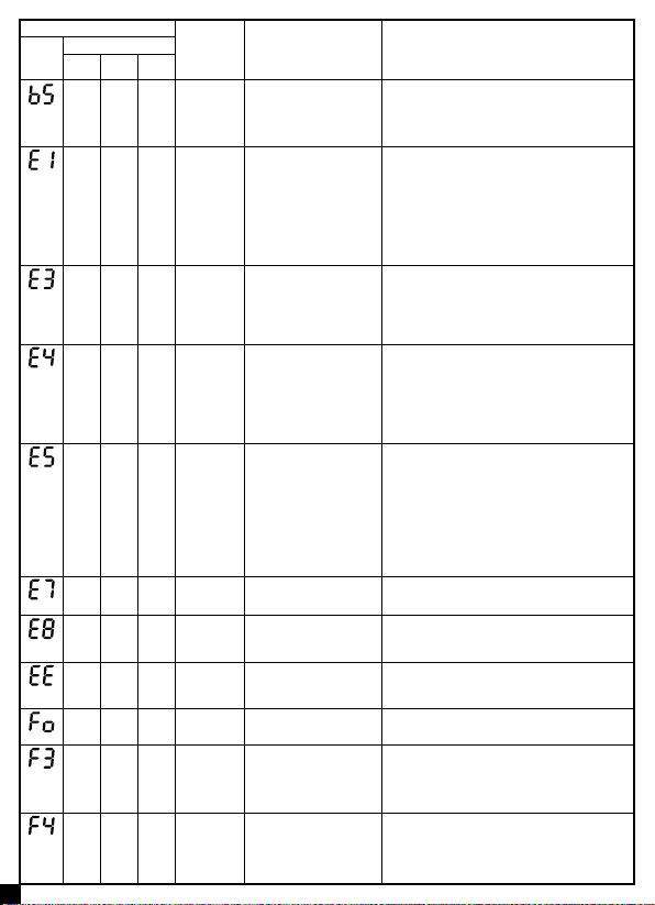
Display method of indoor unit
Malfunction
name AC status Possible causes
Error
code
Indicator display
Power
indicator
Cool
indicator
Heat
indicator
Flash 5
times
Outdoor air
discharge
temperature
is open/short-
circuited
Complete unit stops operation;
motor of sliding door is cut off
power.
1. The exhaust temperature sensor is not connected well or
damaged. (refer to Page 33 “Table 3”)
2.Temperature sensor wire of outdoor unit is damaged; short
circuit between the temperature sensor and copper pipe or
outer case
3.Main board of outdoor unit is damaged;
Malfunction of
micro switch
Cool/Dry: compressor stops
operation, while indoor fan
operates;
Heat: all loads stops operation.
1. The sliding door is blocked;
2. Malfunction of the photoelectric inspection panel of sliding
door;
Flash 4
times
System is
abnormal
Cool/Dry: all loads stops
operation except indoor fan;
Heat: all loads stops operation.
See Page 17 “High temperature prevention protection; high
power; system isabnormal”
Flash 7
times
Desynchronizing of
compressor
Cool/Dry: compressor stops
operation, while indoor fan
operates; Heat: all loads stops
operation.
See “Page 19 “Desynchronization diagnosis for compressor”
Flash 6
times
PFC protection Cool/Dry: compressor stops
operation, while indoor fan
operates; Heat: all loads stops
operation.
1. The power grid quality is bad; AC input voltage uctuates
sharply;
2. Power plug of air conditioner or wiring board or reactor is not
connected reliably;
3. Indoor and outdoor heat exchanger is too dirty, or air inlet/
outlet is blocked;
4. Main board of outdoor unit is damaged.
Flash
14
times
Demagnetization
protection of
compressor
Cool: compressor and outdoor fan
stop operation; Heat: compressor
and outdoor fan stop operation at
rst; about 1min later, indoor fan
stops operation.
1. The main board of outdoor unit is damaged;
2. Compressor is damaged;
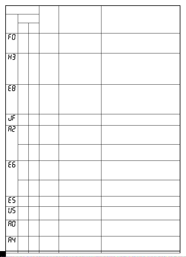
Communication
malfunction
between indoor
unit and inspection
board
Normal operation 1. Poor connection between the indoor unit and the inspection
board.
2.The main board of indoor unit is damaged;
3. The inspection board is damaged;
Malfunction of
humidity sensor
Compressor, outdoor fan and
indoor fan stop operation;
The inspection board is damaged.
High power
protection
Cool: compressor and outdoor
fan stops operation, while indoor
fan operates.
See Page 17 “High temperature prevention protection; high
power; system isabnormal”
Flash
11
times
Start-up failed Cool/Dry: compressor stops,
while indoor fan operates; Heat:
all loads stops operation.
See Page 20 “Malfunction diagnosis for failure startup”
Lost phase Cool: compressor and outdoor fan
stop operation; Heat: compressor
and outdoor fan stop operation at
rst; about 1min later, indoor fan
stops operation.
1. The main board of outdoor unit is damaged;
2. The compressor is damaged;
3. The connection wire of compressor is not connected well.
Undened
outdoor unit
error
Cool: compressor and outdoor
fan stops operation, while indoor
fan operates; Heat: compressor,
outdoor fan and indoor fan stop
operation.
1. Outdoor ambient temperature exceeds the operation range
of unit (eg: less than-20oC or more than 60oC for cooling; more
than 30oC for heating);
2. Are wires of compressor not connected tightly?
3. Failure startup of compressor?
4. Is compressor damaged?
5. Is main board damaged?
Flash
15
times
Over-phase
current
protection of
compressor
Cool/Dry: compressor stops
operation, while indoor fan
operates; Heat: all loads stops
operation.
See “Page 13 “Overload protection of compressor , High
discharge temperature protection of compressor”
Flash
16
times
Communication
malfunction
between the
drive board and
the main board
Cool: compressor and outdoor
fan stops operation; Heat:
compressor and outdoor fan stop
at rst; about 1min later, indoor
fan stops operation;
1. The drive board is damaged;
2. The main board of outdoor unit is damaged;
3. The drive board and the main board is not connected well.
Flash
18
times
Circuit
malfunction
of module
temperature
sensor
Cool/Dry: compressor stops
operation, while indoor fan
operates; Heat: all loads stops
operation.
Replace outdoor control board