Argo XFETTO DCI HPL User manual

EG
I
F
D
E
P
GR
OPERATING INSTRUCTION ●ISTRUZIONI D’USO ●NOTICE D’UTILISATION
BEDIENUNGSANLEITUNGEN ●INSTRUCCIONES DE USO
MANUAL DE INSTRUÇÕES ●OODDHHLLIIEESSCCRRHHSSEEWWSS
INSTALLATION INSTRUCTION ●ISTRUZIONI D’INSTALLAZIONE ●NOTICE D’INSTALLATION
INSTALLATIONSANLEITUNGEN ●INSTRUCCIONES DE INSTALACION
INSTRUÇÕES DE INSTALAÇÃO ● OODDHHGGIIEESSTTOOPPOOQQEETTHHSSHHSS
XFETTO DCI
HPL / SCL V2
37.4252.045.00 06/2013
Air conditioner •
Climatizzatore d’aria
• Climatiseur
Klimagerät
• Acondicionador de aire
Aparelho de ar condicionado
• KKlliimmaattiioottiikkoovv

DECLARATION OF CONFORMITY
If you have problems or questions concerning your Air
Conditioner, you will need the following information. Model
and serial numbers are on the nameplate applied on the unit.
Model No.
Serial No.
Date of purchase
Dealer’s address
Phone number
The following symbols used in this manual, alert you to
potentially dangerous conditions to users, service personnel
or the appliance:
This symbol refers to a hazard or unsafe practice which
can result in severe personal injury or death.
This symbol refers to a hazard or unsafe practice which
can result in personal injury or product or property damage.
CONTENTS
1
PRODUCT INFORMATION ALERT SYMBOLS
EG
WARNING
CAUTION
This air conditioner is equipped with cooling, drying, heating and fan functions. Details on these functions are provided
here following; refer on these descriptions when using the air conditioner. This product is covered by patent nr. 261412
issued on the 8th of Genuary 2009.
NOTE
This product is marked as it satisfies
Directives.
- Low voltage no. 2006/95/CE.
- Electromagnetic compatibily no.
2004/108/CE, 92/31/CEE and 93/68/CEE.
This declaration will become void in case of
misusage and/or non observance though
partial of Manufacturer’s installation and/or
operating instructions.
COOLING
OUTDOOR TEMPERATURE 43°C D.B.
ROOM TEMPERATURE 32°C D.B./23°C W.B.
OUTDOOR TEMPERATURE -15°C D.B.
ROOM TEMPERATURE 10°C D.B./6°C W.B.
HEATING
OUTDOOR TEMPERATURE 24°C D.B./18°C W.B.
ROOM TEMPERATURE 27°C D.B.
OUTDOOR TEMPERATURE -15°C D.B.
INDOOR ROOM 30% R.H.
OUTDOOR TEMPERATURE 43°C B.S.
ROOM TEMPERATURE 32°C B.S. / 80% R.H.
OUTDOOR TEMPERATURE -15°C B.S.
ROOM TEMPERATURE 10°C B.S. / 80% R.H.
MAXIMUM CONDITIONS
MINIMUM CONDITIONS
MAXIMUM CONDITIONS
MINIMUM CONDITIONS
DEHUMIDYFING (DRY)
MAXIMUM CONDITIONS
MINIMUM CONDITIONS
INFORMATION FOR
CORRECT DISPOSAL OF THE
PRODUCT IN ACCORDANCE
WITH THE EUROPEAN
DIRECTIVE 2002/96/EC
At the end of its working life this
equipment must not be disposed of as
an household waste.
It must be taken to special local
community waste collection centres or
to a dealer providing this service.
Disposing of an electrical and electronic
equipment and its batteries separately
avoids possible negative effects on the
environment and human health deriving
from an inappropriate disposal and
enables its components to be
recovered and recycled to obtain
significant savings in energy and
resources.
In order to underline the duty to dispose
of this equipment and batteries
separately, the product is marked with
a crossed-out dustbin.
PRODUCT IDENTIFICATION 2
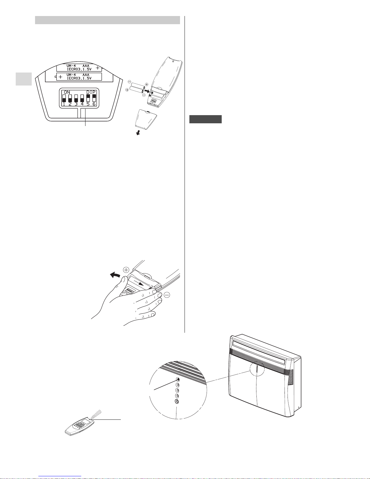
SIGNALING LAMPS 2
ACCESSORIES SUPPLIED WITH THE UNIT 3
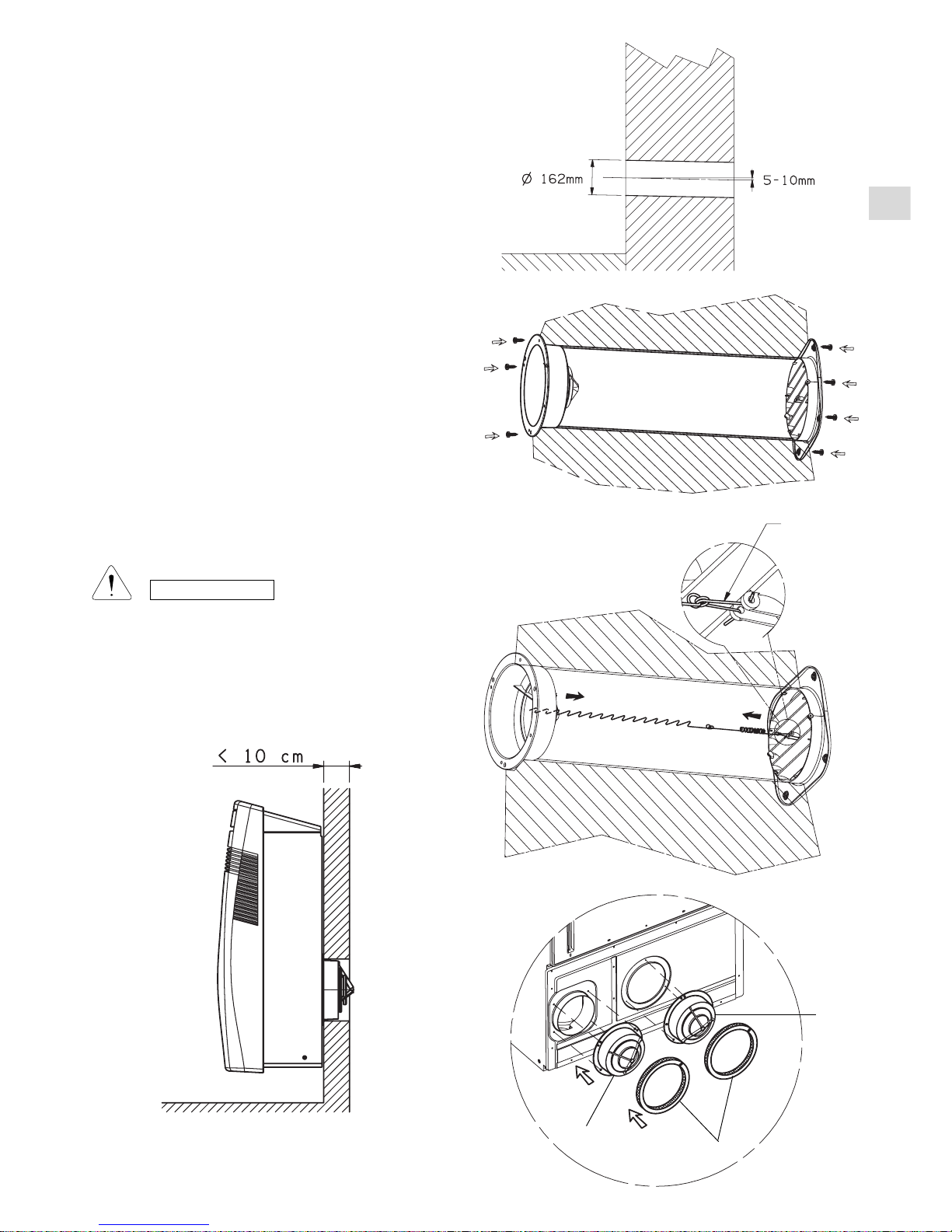
INSTALLATION 3
BEFORE USING THE APPLIANCE 6
USING THE REMOTE CONTROL UNIT 7
REMOTE CONTROL UNIT 8
HOW TO SET THE PRESENT TIME 9
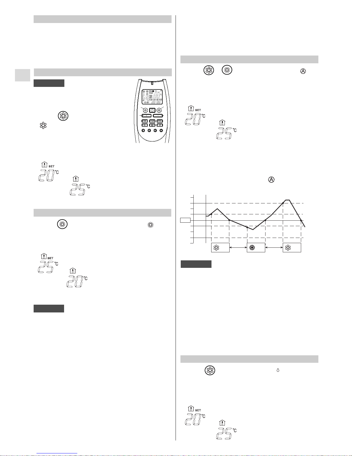
COOLING 9
HEATING 9
AUTOMATIC OPERATION 9
DEHUMIDIFYING (DRY) 9
FAN ONLY 10
ADJUSTING THE FAN SPEED 10
NIGHT MODE / ENERGY SAVING 10
ELECTRICAL HEATING 10
HIGH POWER MODE 10
SETTING THE TIMER 11
ADJUSTING THEAIR FLOW DIRECTION 12
OPERATION WITHOUT THE REMOTE CONTROL UNIT 12
TIPS FOR ENERGY SAVING 12
TROUBLESHOOTING 13
HOW TO DISCHARGE THE CONDENSATE WATER 14
CARE AND CLEANING 14
F-GAS Regulation (EC) No. 842/2006
Do not vent R410A into atmosphere: R410A
is a fluorinated greenhouse gas, covered by
Kyoto Protocol, with a Global Warming Potential
(GWP) = 1975.
OPERATING LIMITS

2
EG
PRODUCT IDENTIFICATION
1. Wireless remote control unit
2. Signaling lamps
3. Supply air deflector
4. Lateral air intake grilles
5. Front air intake grille
6. Air filter
7. Electric cable with plug
8. Air inlet hole
9. Air outlet fan
10. Suspension panel
11. Service tube for condensate discharge
12. Tube for condensate discharge
SIGNALING LAMPS
1. Receiver : receives signals transmitted from the remote
control.
2. TIMER lamp: This lamp lights up when the system is
being controlled by the timer.
3. STANDBY lamp: This lamp lights up when the air
conditioner is connected to the power and ready to
receive the remote control command.
4. OPERATION lamp: This lamp lights up during operation.
It blinks together with other lamps in case of troubles (see
AUTO-DIAGNOSIS table).
The OFF position does not disconnect the power. Use
the main power switch to turn off power completely.
WARNING
1
23
4
5
6
7
8
9
10
11
12
5. Operation button (without remote control): Push the
button to change from one operation mode to the other
(OFF, COOL and HEAT).
NOTES
●It is possible to set the air conditioner in order to let
the OPERATION, TIMER and STANDBY lamps always
OFF, even during operation.
Press contemporary the IFEEL and FAN buttons on
the remote control unit for more then 5 seconds.
Repeat the same procedure to set again the normal
operation conditions.
●In case of troubleshooting the air conditioner
diagnostic system activates the lamps accordingly,
even if they are set to OFF. See paragraph
TROUBLESHOOTING for further details.

3
EG
The installation should be carried out by a qualified installer,
following the instructions as shown.
INSTALLATION SITE SELECTION
●The wall must be a perimeter one.
●Fix the unit at a minimum height of 10 cm and a maximum
height of 100 cm.
●Select a sufficiently strong location to support the weight
of the unit.
●Allow access for maintenance operation around the unit.
●Make sure that there are no obstacles around the unit
affecting the free circulation of air.
●Avoid installing the unit with the air flow directly toward
passerby people, electric appliances or heat sources.
CAUTION
After the selection of the installation site, according to
the above mentioned points, be sure not to make holes
in areas where electrical wiring or conduits are located,
damaging them.
Make sure that there are no obstacles in the conduits
inside the wall affecting the free circulation of the
external air. The unit must be kept at a minimum
distance of 80 cm from any wall or obstacle.
INSTALLATION
1. PLASTIC TUBE (1pcs.)
2. EXTERNAL GRILLES (2pcs.)
3. INTERNAL GRILLES (2pcs.)
4. TENSION BARS (2pcs.)
5. FULL SCALE DIAGRAM (1pcs.)
6. RAWL PLUGS + SCREWS (15pcs.)
7. REMOTE CONTROL UNIT (1pcs.)
8. BATTERIES FOR REMOTE CONTROL (2pcs.)
ACCESSORIES SUPPLIED WITH THE UNIT
5
1
2
3
4
6
8
Level
Full scale
diagram
Mill
MOUNTING OF THE UNIT
- Apply at the wall the full scale diagram, fix and level it.
- Drill the two holes Ø 162 mm and eventually the hole
Ø 35 mm in case of heat pump unit for the condensate
drainage toward the outside (assure a positive slope
toward the outside).
7

4
EG
- Insert in the two holes the supplied plastic tube; cut it at
the right length: it is necessary to measure the thickness
of the wall and subtract 70 mm.
- Fix the two anti-intrusion grilles and the two external grilles
with the blades toward the bottom using wall rawl plugs
and screws.
- In case it is not possible to fix the two external grilles
directly at the wall, hook the two grilles to the internal
ones using the supplied tension bars, as follows:
a) Bend them, fix the hook of the spring, insert them
inside the tube and open them toward the outside.
b) Choose the proper hook of the tension bar in order to
lengthen the spring of 15-20 mm and hook it to the
internal grille.
c) Eliminate the exceeding part of the tension bar cutting
it near the hooking points.
Spring
hook
3
3
a
- In case of very thin walls (less than 10 cm) it is necessary
to mount the internal anti-intrusion grilles on the back of
the unit removing the gaskets (a) from the back side and
applying them around the grilles. The tube and the external
grilles will not be used.
CAUTION
The manufacturer assumes no responsibilities if this
safety instruction is not observed.
INSIDE OUTSIDE

5
WARNING! The supplied plastic conduits can be used for
wall thickness up to 50 cm; in special cases (i.e. installations
in a garret) it can be necessary to utilise longer tubes. The
maximum allowable length is 2 m. You can go to any building
material retailer, buy the plastic tube of the same diameter
(ø160 mm), of the proper length and cover it outside with
insulating material (thickness: about 3-4 cm).
- Fix the suspension panel to the wall in the position indicated
on the full scale diagram.
The quantity and the type of rawl plugs (not supplied)
depends on the consistence of the wall; do not let any
space between the panel and the wall.
- Hang up the unit at the panel inserting the back fan outlet
in the grille.
- Predispose a condensate drainage toward the outside
(a) making a hole Ø 35 mm as indicated on the full scale
diagram; if it is not possible, maintain the condensate
tube inside (b) and make a proper drainage.Assure always
a positive slope of at least 1cm/m.
- Connect the unit inserting the plug in the power socket.
- Verify the correct operation.
EG
Plastic tubes ø 160mm
Insulation
(a)
(b)
(b)

6
BEFORE USING THE APPLIANCE
●Check that the power supply at the location where the air conditioner is going to be used is 220-240V ~ 50Hz .
●Make sure that the electrical installation is suitable to supply continuously current necessary for the air conditioner in
addition to that already used by other electric appliances (white goods, lighting). See the max electric input indicated
on the name plate positioned on the air conditioner.
●The installation of a double-pole switch, protected by 16Afuses of the delayed type, upstream the electricity wall socket,
is recommended.
●The unit has to be connected according to the local electrical rules.
●Make sure that circuit breakers, fuses, etc, are of sufficient capacity to handle a start-up current of 20A(generally less
then 1 second).
●Do not install the air conditioner where it could be wetted by drops of water (i.e. in laundries).
●Before connecting the air conditioner to a power socket, make sure that the socket is provided with an earth connection
in compliance with local codes.
●Never use the power plug as a mean to start or stop the air conditioner: always use the ON/OFF button of the remote
control unit or the operation button on the unit.
●WARNING! Do not stick anything into the air outlet of the air conditioner. This is very dangerous because the fan is rotating
at high speed.
●WARNING!
The air conditioner is provided with a time-guard system, which does not allow re-starting of compressor until after 3
minutes from a previous stop.
●Make sure that there are no obstacles around the unit affecting the free circulation of air. Do not block the air intakes
and outlet of the unit with curtains or other. Never put objects on the top of the unit.
●When you switch on the air conditioner for the first time, it reaches the maximum efficiency after at least one hour of
operation.
●The manufacturer assumes no responsibilities if the safety regulations or local codes are not observed.
Always unplug the unit from the power socket before moving or cleaning it and, in case you should remove it, discharge
the eventual condensate water inside the bottom plate.
WARNING
EG

EG
7
HOW TO INSTALL BATTERIES
●Remove trhe lid in the rear part of the remote control unit
and check the settings of the dipswitch as shown below:
USING THE REMOTE CONTROL UNIT
OPERATION WITH THE REMOTE CONTROL UNIT
When using the remote control unit, always point the unit
transmitter head directly at the air conditioner receiver.
HOW TO TURN ON THE AIR CONDITIONER
Press the ON/OFF button to turn the air conditioner on.
The operation lamp will light up, indicating the unit is in
operation.
TRANSMITTER
HEAD
REMOTE
CONTROL UNIT
UNIT
RECEIVER
●Insert two AAA alkaline batteries of 1,5 V-DC making
sure that point in the direction marked in the battery
compartment.The displayed time flashes.
Press the SEL TYPE button.
Remote controller is now ready for operation.
●The batteries last about six months. Depending on how
much you use the remote control unit.
Remove the batteries if you do not use the remote control
unit for more than one month.
Replace the batteries when the remote control unit lamp
fails to light, or when the air conditioner does not receive
the remote control unit signals.
●The batteries of the remote control contain polluted
substances exhausted batteries must be disposed
according to the laws in force.
HOW TO REMOVE BATTERIES
●Remove the lid.
●Press the battery
toward the negative
end and lift it out by
its positive end (as
shown in the
figure).
●Remove the other
battery in the same
way.
SWITCHES
TEMPERATURE SENSOR SELECTOR
●Under normal conditions the room temperature is detected
and checked by the temperature sensor placed in the
remote controller (I FEEL icon displayed ).This function
is designed to provide a comfortable room temperature
by transmitting the temperature control command from the
location next to you. When using this function, the remote,
control should always be pointed at the air conditioner,
therefore it should be placed in a position in which it is
visible by the indoor unit (for example, do not put it in a
drawer).
●It is possible to disable the remote controller room sensor
pressing the I FEEL button. In this case the I FEEL icon
on the remote controller display lights off and only the
sensor placed in the air conditioner becomes active.
The remote control unit transmits signals to the indoor
unit each time you press a key and at any temperature
change detected by the IFEEL sensor. In case of
troubles (low batteries, remote control placed in a
position not visible by the indoor unit,...) room
temperature control is automatically switched to the
sensor of the indoor unit. In this case, the temperature
around the remote control unit may differ from the
temperature detected in the air conditioner position.
NOTE

8
EG
ELECTRICAL HEATING BUTTON
REMOTE CONTROL UNIT
DISPLAY
Information is displayed when the remote controller is switched on.
If switched off, only the operating mode, the room temperature and
the clock are shown
Operation mode
Fan speed
High speed
Automatic Medium speed
Low speed
Displayed when
transmitting data
Set point
temperature
I FEEL mode is active
(remote controller
sensor active)
Timer modes
Automatic
Cooling
Heating
Dehumidification
Fan
C
Clock
Room
temperature
Night
mode Oscillation
Flap HIGH POWER
mode
TRANSMITTER
When you press the
buttons of the remote
control unit, the
mark appears
on the display to
transmit the setting
changes to the
receiver in the air
conditioner.
HOURS AND MINUTES SETTING
BUTTONS
With these buttons is possible to set the
clock and the timer. For details refer to
paragraphs “ SETTING THE HOUR” and
“SETTING THE TIMER”.
TIMER SELECTION BUTTON
Press this button to select the type of timer
to activate. For details refer to paragraph
“SETTING THE TIMER”.
MODE SELECTOR BUTTON
Press this button to modify the air
conditioner mode.
(heating)
The air conditioner makes the room warmer.
(automatic)
When this setting is selected, the air
conditioner calculates the difference
between the thermostat setting and the
room temperature and automatically
switches to the "cool" or "heat" mode.
(electrical heating)
FAN HEATER MODE
C
TEMPERATURE SETTING BUTTONS
- (cooler)
Press this button to decrease the set
temperature.
+ (warmer)
Press this button to increase the set
temperature.
SENSOR
A temperature
sensor inside the
remote control unit
detects the room
temperature.
CLOK AND TIMER SETTING BUTTON
Press this button in order to:
• set the clock
• set the ON/OFF timer
For details refer to paragraphs “SETTING
THE HOUR” and “SETTING THE TIMER”.
IFEEL/IFEEL C SENSOR SELECTOR
Press this button to modify the active setting
for room temperature detection (from remote
controller to air conditioner and viceversa).
“FAN “ BUTTON (fan speed)
Fan speed is automatically
selected by the microcomputer.
High speed.
Medium speed.
Low speed.
ON/OFF BUTTON
This button turns the air conditioner ON
and OFF.
FLAP BUTTON
Press this button in order to select the
desired function.
Fixed: six position
Continous oscillations
Automatically oscillations
NIGHT/ECO BUTTON
Press this button in order to select the
NIGHT/ECO mode.
“HIGH POWER” BUTTON
MODE SELECTOR BUTTON
Press this button to modify the air
conditioner mode.
(cooling)
The air conditioner makes the room cooler.
(dry)
The air conditioner reduces the humidity in
the room.
(automatic)
When this setting is selected, the air
conditioner calculates the difference
between the thermostat setting and the
room temperature and automatically
switches to the "cool" or "heat" mode.
(fan)
The air conditioner works only as a
circulation fan.
blinking
Electrical heating is active

EG
9
THE DISPLAY SHOWS THE SELECTED
TEMPERATURE.
AFTER 5 SECONDS FROM THE REQUIRED
TEMPERATURE SETTING THE DISPLAY WILL
SHOW THE ROOM TEMPERATUREAGAIN.
C
Verify that the unit is connected to the
main power and the STANDBY lamp is
light up.
1.Set the selector to COOL (symbol
on the display).
2.Press the +/- buttons (temperature
selection) to set the desired temperature
(the temperature range is between 32 °C
max. and 10 °C min.).
HOW TO SET THE PRESENT TIME
HEATING
1. Press the button ST three times.
The time indication alone flashes.
2. Press the H button until the present time hour is
displayed. Press the M button until the present time
minutes are displayed. The display will automatically
stop flashing.
1.Set the selector to HEAT (fixed symbol on the
display.
2.Press the +/- buttons (temperature selection) to set the desired
temperature (the temperature range is between 32 °C max.
and 10 °C min.).
THE DISPLAY SHOWS THE
SELECTED TEMPERATURE.
AFTER 5 SECONDS FROM THE
REQUIRED TEMPERATURE SETTING
THE DISPLAY WILL SHOW THE ROOM
TEMPERATURE AGAIN.
3.Press the FAN button to select the fan speed.
For several minutes after the start of heating operation, the
indoor fan will stop until the indoor heat exchanger coil has
warmed up sufficiently. This is because the COLD DRAFT
PREVENTION SYSTEM is operating. During this period, the
STANDBY lamp remains lit.
NOTE
DEFROSTING OF OUTDOOR UNIT HEAT
EXCHANGER
When the outdoor temperature is low, frost or ice may
appear on the heat exchanger coil, reducing the heating
performance. When this happens, a protection function for
the heat exchanger defrosting is activated. During this
function operation, the fan of the indoor unit stops. Heating
operation restarts after several minutes. (This interval will
vary slightly depending on the room and outdoor
temperature).
COOLING
THE DISPLAY SHOWS THE
SELECTED TEMPERATURE.
AFTER 5 SECONDS FROM THE
REQUIRED TEMPERATURE SETTING
THE DISPLAY WILL SHOW THE ROOM
TEMPERATURE AGAIN.
3.Press the FAN button to select the fan speed.
1
3
2
NOTE
2
1
ONON ON
Δ1 H Δ1 H
MIN. MAX.
A
B
C
C
B
A
27
26
25
24
23
22
21
20
19
AUTOMATIC OPERATION
HEATING PERFORMANCE
Aheat pump conditioner heats a room by taking heat from
outside air. The heating efficiency will fall off when the
outdoor temperature is very low. If enough heat is not
obtained with this air conditioner, use another heating
appliance in conjunction with it.
1.Set the or selector to AUTO (symbol on
the display.
2.Press the
+/- buttons (temperature selection)
to set the
desired temperature (the temperature range is between
32 °C max. and 10 °C min.).
When this setting is selected, the air conditioner calculates
the difference between the thermostat setting and the room
temperature and automatically switches to the COOL or
HEAT mode as appropriate.
3.Press the FAN selector button to the setting you want.
THE DISPLAY SHOWS THE
SELECTED TEMPERATURE.
AFTER 5 SECONDS FROM THE
REQUIRED TEMPERATURE SETTING
THE DISPLAY WILL SHOW THE ROOM
TEMPERATURE AGAIN.
Example of operation diagram in the (Auto) mode with
the set room temperature at 23°C.
NOTE
The air conditioner changes the operation mode (from cool
to heat or vice versa, if one of the following conditions
occurs:
-ZONE A: changes if the difference between the room
temperature and the temperature set on the remote control
unit is at least 3°C.
-ZONE B: changes if the difference between the room
temperature and the temperature set on the remote control
unit is at least 1°C, one hour after the compressor stop.
- ZONE C: never changes if the difference between the
room temperature and the temperature set on the remote
control unit is no more than 1°C.
1.Set the button to DRY. The icon is displayed.
2.Press the
+/- buttons (temperature selection)
to set the
desired temperature (the temperature range is between
32 °C max. and 10 °C min.).
DEHUMIDIFYING (DRY)

10
EG
●Use DRYoperation when you want to reduce the humidity
in the room.
●Once the room temperature reaches the set level, the unit
repeats the cycle of turning on and off automatically.
●During DRYoperation, the fan speed is automatically set
(Remote control lamp is ON) to prevent overcooling.
●Dry operation is not possible if the indoor temperature is
10 °C or less.
NOTE
ELECTRICAL HEATING
This air conditioner is equipped with an electrical heater
that can operate in three ways:
- AUTO MODE - During AUTOMATIC OPERATION the
electrical heater switches on automatically depending on the
room temperature, the set temperature and the outdoor
temperature.
- BOOSTER - During HEATING OPERATION press the
button on the remote control in order to activate the
electrical heater that will switch on only depending on the
room temperature and the set temperature.
- FAN HEATER - During FAN OPERATION press FILTER
button on the remote control or press three times the
selector (blinking symbol on the display) in order to
activate the electrical heater.
FAN ONLY
If you want to make air circulate without any temperature
control, press button until only the fan symbol
appears on the display.
ADJUSTING THE FAN SPEED
AUTOMATIC
Simply set the FAN selector to the position.A
microcomputer automatically controls the fan speed when
theAUTO mode is selected. When the air conditioner starts
operating, in heating or cooling, the fan speed varies (high
- medium - low - very low) according to the thermal load of
the room.
The automatic speed is not available in FAN ONLY mode.
NOTE
High speed Med. speed Low speed
MANUAL
If you want to manually adjust speed just set the FAN selector
as desired.
NIGHT MODE / ENERGY SAVING
●This mode enables you to save energy.
1. Set the or selector to cool, dry or heat.
2. Press the button.
3. The mark appears on the display. Press the
button again to release the function.
What does the NIGHT mode mean?
When you select the NIGHT mode, the air conditioner will
modify automatically the set temperature after 60 minutes.
This enables you to save energy without sacrificing your
comfort.
OPERATING MODE SET TEMPERATURE CHANGE
Heating Lowered by 1 °C
Cooling and Dehumidifying Raised by 2 °C
During the NIGHT mode the internal fan speed is
automatically lower and reduces the noise.
NOTA
COOLING AND DEHUMIDIFYING
HEATING
Function selection
Room temperature
TIME
Function selection
Room temperature
TIME
HIGH POWER MODE
You can select High Power only during cooling or heating
mode and not during automatic, dehumidifying (dry) and
fan mode. High Power mode allows to obtain the maximum
air conditioner’s efficiency, either in cooling or heating mode
(heat pump). The user can choose to activate the High
Power mode, using the remote control unit, after having
selected cooling or heating mode and during this latter
mode, it can be used together with the electrical heater in
Booster way. Under these conditions the air conditioner
will reach its maximum thermal power and consequently
also the maximum electrical consumption and noise; it is
recommended to use the High Power mode only if the
outdoor temperature is very low and the selected room
temperature is difficult to be reached. On the contrary, if
you want to obtain the best performance in efficiency and
silentness, High Power mode is not recommended: let the
air conditioner run in normal condition (factory default
program).
To activate High Power mode it is necessary (after having
selected the cooling or heating mode) to press two times
the HIGH POWER button (always waiting for the
acoustic signal confirmation); at the first pressure of the
button the symbol .....switches on, at the second pressure
this symbol disappears; at this point the operation lamp
(green lamp on the front panel of the air conditioner) begins
blinking slowly, indicating that High Power mode is activated;
it can be deactivated using the same procedure; therefore
the green lamp will stop blinking and it will be switched on
permanently.

EG
11
NOTES
●During the high power operation the room temperature
could not correspond to the set temperature.
●HIGH POWER program remains set also if you change
operation mode from COOL to HEAT or vice versa and
if you switch OFF and ON again the air conditioner.
SETTING THE HOLIDAY TIMER
The Holiday Timer function allows you to activate the indoor
unit (either it is the only one of a monosplit system or one
unit of a multisplit system), with a dalay up to 99 days you
can set for the Daily Timer, On Timer, Off Timer functions
(not available for 1 HOUR TIMER) already explained in this
manual.
With this function you can set the air conditioner to be
switched on again after a long week end, a holiday of one
week or more, ecc…
To activate this function you have to follow the following
steps in order :
1. Keep pressed the button “TIMER SELECTION” of the
remote control unit (clock figure) for more than 6~7
seconds. In this way you enter the menu to select the
number of days of delay.
2. Select the desired timer (Daily Timer, On Timer, Off
Timer) pressing on the same button “TIMER
SELECTION”.
3. Set the desired number of days of delay using the button
“+” .
4. Keep pressed again the button “TIMER SELECTION” for
more than 6~7 seconds. You enter again the normal
menu of the remote control unit.
At this point, the symbol of the desired timer will flash and
the selected timer will be activated only after the set number
of delay days.
C
1 - 2 - 4
3
A)HOW TO SET THE ON TIME
1. Press the ST button once.
The ON and time indications flash.
2. Press the H button until the designed
hour is displayed.
Press the M button until the designed
minutes are displayed. The display will
change automatically back to show the
present time after 10 sec.
3. Press the ON/OFF button to start the air
conditioner.
4. Press the button to activate the ON
timer.
B) HOW TO SET THE OFF TIME
1. Press the ST button twice.
The OFF and time indications flash.
2. Press the H button until the designed
hour is displayed.
Press the M button until the designed
minutes are displayed. The display will
change automatically back to show the
present time after 10 sec.
3. Press the ON/OFF button to start the air
conditioner.
4. Press the button two times to
activate the OFF timer.
C) HOW TO SET A PROGRAM FOR
DAILY ON/OFF OPERATION (OR
VICEVERSA)
1. Set the timer ON/OFF as shown in A)
and B).
2. Press the ON/OFF button to start the air
conditioner.
3. Press three times the button to
activate the DAILY timer.
SETTING THE TIMER
After timer setting, press ST button in order to check the
ON/OFF setting time.
NOTE
C
4
2
2
3
1
TIMER SETTING PROCEDURE.
●Press four times the button.The 1
HOUR TIMER mark will appear on the
display.
CANCELLATION PROCEDURE
●Press the ON/OFF button to turn the air conditioner off.
●Wait for the indoor unit to stop operating.
●Press the ON/OFF button again to turn the air conditioner
on.
SETTING THE 1 HOUR TIMER
This function causes the unit to operate for one hour at the
set conditions, regardless of whether the unit is on or off.

EG
12
ADJUSTING THE AIR FLOW DIRECTION
Set vertical vanes to the front position during COOLING/DRY
operation if humidity is high.
If the vertical vanes are set to the left-most or right-most
position, condensation will form around the air outlet and
drip off.
CAUTION
HORIZONTAL (manual)
The horizontal air flow can be adjusted by moving the vertical
vanes to the left or right, as indicated in the following figures.
VERTICAL (with remote control unit)
Make sure that the remote control unit has been turned on. Press
the FLAP button to select the sweep function or to choose one of
the six positions of the flap.
CAUTION
Do not move the flap with your hands when the air conditioner
is running.
Vertical vane
Sweep function
The flap starts moving up and down to deliver air over the
sweep range.
NOTES
• The flap automatically closes when the unit is off.
• During the heating operation, the fan speed will be very low and
the flap will be in the horizontal position (position
d
) until the air
being blown out of the unit begins to warm. Once the air warms
up, the flap position and fan speed change to the settings
specified with the remote control.
• Use the FLAP button on the remote control to adjust the
position of the flap. If you move the flap by hand, the factual
flap position and the flap position on the remote control
may no longer match. If this should happen, shut off the
unit, wait for the flap to close, and then turn on the unit
again; the flap position will now be normal again.
CAUTION
2. WHEN THE AIR CONDITIONER IS RUNNING
If you want to turn off the air conditioner push the
OPERATION BUTTON until the OPERATION lamp is turned
off.
If you have lost the remote control unit or it has troubles,
follow the steps below.
1. WHEN THE AIR CONDITIONER IS STOPPED
If you want to turn on the air conditioner push the
OPERATION BUTTON to select the desired mode (COOL
or HEAT).
OPERATION WITHOUT THE REMOTE
CONTROL UNIT
TIPS FOR ENERGY SAVING
DO NOT:
●Block the air intake and outlet of the unit.
If they are obstructed, the unit will not work well, and
may be damaged.
●Let direct sunlight into the room. Use sunshades,
blind or curtain.
DO:
●Always try to keep the air filter clean. A clogged filter
will impair the performance of the unit.
●To prevent conditioned air from escaping, keep windows,
doors and any other openings closed.
The air conditioner will start in HIGH fan speed.
The temperature setting is 25°C for cooling mode and
21°C for heating mode.
NOTE
Power failure during operation.
In the event of power failure, the unit will stop. When the
power is resumed, the unit will restart automatically after 3
minutes.
NOTE
Operation
button

EG
POSSIBLE CAUSE
STANDBY OPERATION TIMER
F F O Defective indoor air sensor
FF
●Defective outdoor air sensor
O F F Defective indoor air coil sensor
●F F Defective outdoor air coil sensor
F O O Defective compressor discharge temperature sensor
F●O Malfuctioning of electronic PCB (current protection)
FO●Malfuctioning of electronic PCB (temperature protection)
F●●Malfuctioning of PFC (power factor correction system)
O F O Malfunctioning of the condensate drainage system
LEDS
AUTO-DIAGNOSIS
O = LED OFF
● = LED ON
F = Flashing LED
13
•If your air conditioner does not work properly, first check
the following points before requesting service.
If it still does not work properly, contact your dealer or
service centre.
TROUBLESHOOTING
WARNING
•The use of portable telephones near the air conditioner
may cause disturbance to its normal operation and must
be avoided. In case abnormal operation is noticed,
(OPERATION lamp lights, but the air conditioner will not
run) to restore normal operation turn-off electric supply for
about 3 minutes, by disconnecting the main switch or the
wall plug, then start again the air conditioner.
Trouble: the air conditioner does not run at all.
Possible cause:
1. Power failure.
2. Leakage breaker tripped.
3. Operation button is OFF.
4. Batteries in remote control unit have run down.
Remedy:
1. Restore power.
2. Contact service centre.
3. Press the button again.
4. Replace batteries.
Trouble: Poor cooling or heating performance.
Possible cause:
1. Dirty or clogged air filters.
2. Heat source or many people in room.
3. Doors and/or windows are open.
4. Obstacle near air intake or air discharge port.
5. The set temperature on the remote control unit is too
high.
6. Outdoor temperature is too low (heat pump version).
Remedy:
1. Clean air filters to improve airflow.
2. Eliminate heat source if possible.
3. Shut them to keep the heat or cold out.
4. Remove it to ensure good airflow.
5. Set the right temperature on the remote control unit.
6. Try to use a back-up heater.
Trouble: Clicking sound is heard from the air conditioner.
Possible cause:
1. During operation, any plastic parts may expand or shrink
due to a sudden temperature change. In this event, a
clicking sound may occur.
Remedy:
1. This is normal, and the sound will disappear when an
even temperature is settled.
Trouble: The electrical heating does not run.
Possible cause:
1. The required temperature is too low.
2. The electrical heater has not been activated.
Remedy:
1. Set an higher temperature on the remote control.
2. Activate the electrical heater pressing the FILTER button
of the remote control (only during HEATING and FAN
mode).

14
EG
●Always switch off the air conditioner before unplugging
it from the power socket.
●Always unplug the air conditioner before discharging the
condensate water collected inside.
WARNING
The Humidity removed by the unit is collected and
discharged automatically, but in special conditions some
condensate water could remain inside the unit.
If you are not going to make use of the air conditioner for
a long period, it is necessary to discharge the eventual
condensate water through the service tube for condensate
discharge placed under the bottom of the unit.
At the end of the operation close the tube with its stopper.
HOW TO DISCHARGE THE CONDENSATE WATER
IMPORTANT
CARE AND CLEANING
WARNING! For safety’s sake, be sure to turn the air conditioner
OFF and also disconnect it from the power supply before cleaning
it.
1. Cleaning of the Air Filter
The air filter must be checked at least once every two weeks
operation. Operation with a dirty filter always causes a lower
efficiency of the air conditioner and severe product damage.
The filter is located at the back of the front intake grille: open
the grille pulling downward the two hooks, grasp the air filter and
pull upwards. Use a vacuum cleaner to remove light dust. If
there is sticky dust on the filter, wash it with lukewarm soapy
water, then rinse in clean, cold water and dry it before
reinstallation.
2. Cleaning of Casing and Grilles.
To clean the air conditioner, wipe it with a clean soft cloth, lightly
moisted. In case it is stained, moisten the cloth with soapy
water. Never use solvents or harsh chemicals, nor very hot
water. Do not pour water over the air conditioner to clean it:
this will damage the internal components and cause an electric
shock hazard.
3. After use.
If you are not going to make use of the air conditioner for a
long period, clean the air filter and verify that there is no
condensate water inside the bottom of the unit (see paragraph
“HOW TO DISCHARGE THE CONDENSATE WATER”). Do
not put heavy objects on top of the unit.
4. Transport.
Keep the air conditioner in the vertical position during
transportation.
5. For your safety care check periodically the conditions of
the electric supply cable; the electrical connection of the
unit is Y type with cable prepared in a special way; in case
you should notice any damage due to usage, call the
nearest After Sale Service to get the cable replaced.
Air filter
Intake grille

Via Varese, 90 - 21013 Gallarate - Va - Italy
Tel. +39 0331 755111 - Fax +39 0331 776240
www.argoclima.com
EG
I
F
D
E
PGR
BLK BLACK
NERO
NOIR
SCHWARZ
NEGRO
PRETO
MAURO
BLU BLUE
BLU
BLEU
BLAU
AZUL
AZUL
MPLE
BRN BROWN
MARRONE
MARRON
BRAUN
MARRÓN
CASTANHO
KAFE
GRN / YEL
GREEN / YELLOW
VERDE / GIALLO
VERT / JAUNE
GRÜN / GELB
VERDE / AMARILLO
VERDE / AMARELO
PRASINO / KITRINO
GRY GREY
GRIGIO
GRIS
GRAU
GRIS
CINZENTO
GKRIZO
ORG ORANGE
ARANCIONE
ORANGE
ORANGE
NARANJA
COR-DE-LARANJA
PORTOKALI
PNK PINK
ROSA
ROSE
ROSA
ROSA
COR-DE-ROSA
ROZ
RED RED
ROSSO
ROUGE
ROT
ROJO
ENCARNADO
KOKKINO
VLT VIOLET
VIOLA
VIOLET
VIOLETT
VIOLETA
VIOLETA
MWB
WHT WHITE
BIANCO
BLANC
WEISS
BLANCO
BRANCO
ASPRO
YEL YELLOW
GIALLO
JAUNE
GELB
AMARILLO
AMARELO
KITRINO
AZU LIGHT BLUE AZZURRO AZUR HIMMEL BLAU AZUL CLARO AZUL CLARO
°∞§∞∑π√
SYMBOL EG
I
F
D
E
PGR
PC - DP CONDENSATE PUMP MOTOR
MOTORE POMPA CONDENSA
MOTEUR POMPE CONDENSATION
KONDENSWASSERPUMPE-MOTOR
MOTOR BOMBA DE AGUA MOTOR BOMBA DE AGUA
ANTLIA APOSTRAGGISHS
CM COMPRESSOR MOTOR
MOTORE COMPRESSORE
MOTEUR DE COMPRESSEUR
KOMPRESSORMOTOR
MOTOR DEL COMPRESOR
COMPRESSOR
SUMPIESTHS
C1, 2, 3,4 CAPACITOR
CONDENSATORE
CONDENSATEUR
KONDENSATOR
CONDENSADOR
CONDENSADOR
SUMPUKNWTHS
DEF THERMO DEFROST THERMOSTAT
TERMOSTATO SBRINATORE
THERMOSTAT DE DEGIVRAGE
ENTFROSTER-THERMOSTAT
TERMOSTATO DE DESCONGELACION
TERMOSTATO DE DESCONGELAÇAO
QERMOSTATHS APOYUXHS
FLP FLAP MOTOR
MOTORE DEFLETTORE
MOTEUR DE VOLET
KLAPPENMOTOR
MOTOR DEL DEFLECTOR
MOTOR DA PLACA
∫π¡∏Δ∏ƒ∞™ ∂∫Δƒ√¶∏™
LM LOUVER MOTOR
MOTORE DEFLETTORE
MOTEUR D’AUVENT
LUFTKLAPPENMOTOR
MOTOR CON ABERTURAS
MOTOR COM ABERTURAS LATERAIS
∫π¡∏Δ∏ƒ∞™ ∂∫Δƒ√¶∏™
FMO OUTDOOR FAN MOTOR
MOTORE ESTERNO VENTOLA
MOTEUR DE VENTILATEUR EXTERIEUR
AUSSENLÜFTERMOTOR
MOTOR EXTERIOR DE LATURBINA
MOTOR DA VENTOINHA EXTERIOR
EXWTERIKOS ANEMISTHRAS
FMI, FM INDOOR FAN MOTOR
MOTORE INTERNO VENTOLA
MOTEUR DE VENTILATEUR INTERIEUR
INNENLÜFTERMOTOR
MOTOR INTERIOR DE LATURBINA
MOTOR DA VENTOINHA INTERIOR
ESWTERIKOS ANEMISTHRAS
IND. ASSY INDICATOR ASSY
GRUPPO INDICATORI
ENSEMBLE INDICATEUR
EANZEIGE-BAUGRUPPE
GRUPO DE INDICADORES GRUPO DE INDICADORES
SET ENDEIKTIKOU
MG MAGNETIC CONTACTOR
CONTATTORE MAGNETICO
CONTACTEUR MAGNETIQUE
MAGNETKONTGEBER
CONTACTOR MAGNÉTICO
CONTADOR MAGNÉTICO
™À™Δ∏ª∞ ª∞°¡∏Δπ∫Ω¡ ∂¶∞ºΩ¡
NF NOISE FILTER
FILTRO RUMORE
FILTRE ANTI PARASSITE
LÄRMSCHUTZFILTER
FILTRO DEL RUIDO
FILTRO DE RUÍDO
FILTRO QORUBOU
OLR OVERLOAD RELAY
RELÉ SOVRACCARICO
RELAIS DE SURCHARGE
ÜBERLASTRELAIS
RELÉ DE SOBRECARGA
RELÉ DE SOBRECARGA
RELE UPERFORTWSHS
CE - PCB CONTROLLER
SCHEDA ELETTRICA
CARTE ELECTRONIQUE
STEUERGERÄT
CONTROLADOR
PAINEL ELÉTRICO
ELEGKTHS
PR POWER RELAY
RELÉ ALIMENTAZIONE
RELAIS D’ALIMENTATION
LEISTUNGSRELAIS
RELÉ DE ALIMENTACIÓN
RELÉ DAALIMENTAÇAO
RELE ISCUOS
RP PUMP RELAY
RELÉ POMPA
RELAIS POMPE PUMPE
RELAIS
RELÉ BOMBA DE AGUA
RELÉ BOMBA
RELE LNTLIA
SSR SOLID STATE RELAY
RELÉ STATO SOLIDO
RELAIS A SEMI-CONDUCTEUR
FESTKÖRPERRELAIS
RELÉ DEL ESTADO SÓLIDO
RELÉ DO ESTADO SÓLIDO
ƒ∂§∂ ™Δ∂ƒ∂∏™ ∫∞Δ∞™Δ∞™∏™
RA STARTING RELAY
RELÉ DI AVVIAMENTO
RELAIS DE DEMARRAGE
STARTRELAIS
RELÉ DE ARRANQUE
RELÉ DE ARRANQUE
RELE EKKINETS
SV SOLENOID VALVE
VALVOLA SOLENOIDE
ELECTROVANNE
MAGNETVENTIL
VÁLVULA SOLENOIDE
VÁLVULA SOLENÓIDE
™Ω§∏¡√∂π¢∏™ μ∞§μπ¢∞
MS - FS SAFETY FLOAT SWITCH
INT. SICUREZZAA GALL.
INTERR. DE SECURITE A FLOTTEUR
SCHWEMM-SCHUTZSCHALTER
INTERR. DE SEGURIDAD DE FLOTADOR INTERR. DE SEGURANÇA DIAKOPTHS ASFALEIAS ME PLWTHRA
ON-OFF SW ON-OFF SWITCH
INTERRUTTORE MARCIA/ARRESTO
TOUCHE MARCHE/ARRÊT
EIN/QUS TQSTE
BOTON ARRANQUE/PARADA INTERRUPTOR LIGAR/DESLIGAR ¢π∞∫√¶Δ∏™ ∫π¡∏™∏™/™Δ∞ª∞Δ∏ª∞Δ√™
TH1, 2, THERMISTOR
TERMISTORE
THERMISTANCE
THERMISTOR
TERMISTOR
TERMISTOR
QERMOSTATHS
PTIMER
PROGRAMMATORE
PROGRAMMATEUR
ZEITSCHALT-UHR
PROGRAMADOR TIMER ¶ƒ√°ƒ∞ªª∞Δπ™Δ∏™
TR1, 2 POWER TRANSFORMER
TRASFORMATORE DI POTENZA
TRANSFORMATEUR DE PUISSANCE
NETZTRANSFORMATOR
TRANSFORMADOR DE POTENCIA
TRANSFORMADOR DE CORRENTE
METASCHMATISTHS ISCUOS
20S 4-WAY VALVE
VALVOLA 4 VIE
VANNE 4 VOIES
4-WEG-VENTIL
VÁLVULA DE 4 VÍAS
VÁLVULA DE 4 VIAS
BAGBIDA 4 DIEUQUNSEXWN
47C NEGATIVE PHASE RELAY
RELÉ A FASE NEGATIVA
RELAIS D’ORDRE DE PHASE
NEGATIVPHASENRELAIS
RELÉ DE FASE NEGATIVA
RELÉ DA FASE NEGATIVA
ƒ∂§∂ ∞ƒ¡∏Δπ∫∏™ º∞™∏™
HWC HOT WATER CONTROL SCHEDA CONTROLLO ACQUA CALDA CARTE ELECTRONIQUE EAU CHAUDE WARMWASSER-
STEUERGERÄT CONTROLADOR AGUA CALIENTE PLACA DE CONTROLO AGUA QUENTE
∫∞ƒΔ∞ ∂§∂°Ã√À ∑∂™Δ√À ¡∂ƒ√À
TM LIMIT WATER THERMOSTAT TERMOSTATO LIMITEACQUA THERMOSTAT DE SEC. NIVEAU EAU WASSERGRENZE-THERMOSTAT TERMOSTATO LIMLITE AGUA TERMOSTATO LIMITE AGUA £∂ƒª√™Δ∞Δ∏™ √ƒπ√À ¡∂ƒ√À
EWV WATER ELECTRIC VALVE ELETTROVALVOLAPASS. ACQUA ELECTROVANNE PASSAGE EAU VENTIL (WASSER-DURCHFLUSS) VALVULAFLUJO DE AGUA VALVULAPASSAGEM DE AGUA ∏§∂∫Δƒ√μ∞§μπ¢∞ ¢π∂§∂À™∏™ ¡∂ƒ√À
E
lectric wiring diagrams’ symbols /
Simboli schemi elettrici
/ Symboles des schemas électriques
Symbole der System-Schaltplanen
/ Símbolos de los esquemas eléctricos / SSuummbblloovvllwwnnHHLLEEKKTTRRIIKKOODDIIAAGGRRAAMMMMAATTWWNNSSUUSSTTHHMMAATTWWNN
Wires color legend
Legenda colori fili elettrici
Légende des couleurs des fils électriques
Beschriftung der Leitungs-Farben
Leyenda de los colores de los cable electricos
PPiivvnnaakkaa""ccrrwwmmaavvttwwnnhhlleekkttrriikkwwvvnnkkaallwwddiivvwwnn
This manual suits for next models
1
Table of contents
Other Argo Air Conditioner manuals

Argo
Argo AWI55AHL Operating manual

Argo
Argo AFIAS11DC User manual

Argo
Argo AW22AL User manual

Argo
Argo Argoclima Magico User manual

Argo
Argo Nuk User manual

Argo
Argo X3MI ECO 52SHB Operating manual

Argo
Argo FCR518CL Operating manual

Argo
Argo KENNY EVO User manual

Argo
Argo AWR609CL User manual

Argo
Argo FCIBS9 Manual