argon audio E-80 User manual

E-80 219A: ASSEMBLY GUIDE
Revision 4.0 - 05-13-2017

Assembly overview.........................................2
1. Frame inspection ........................................3
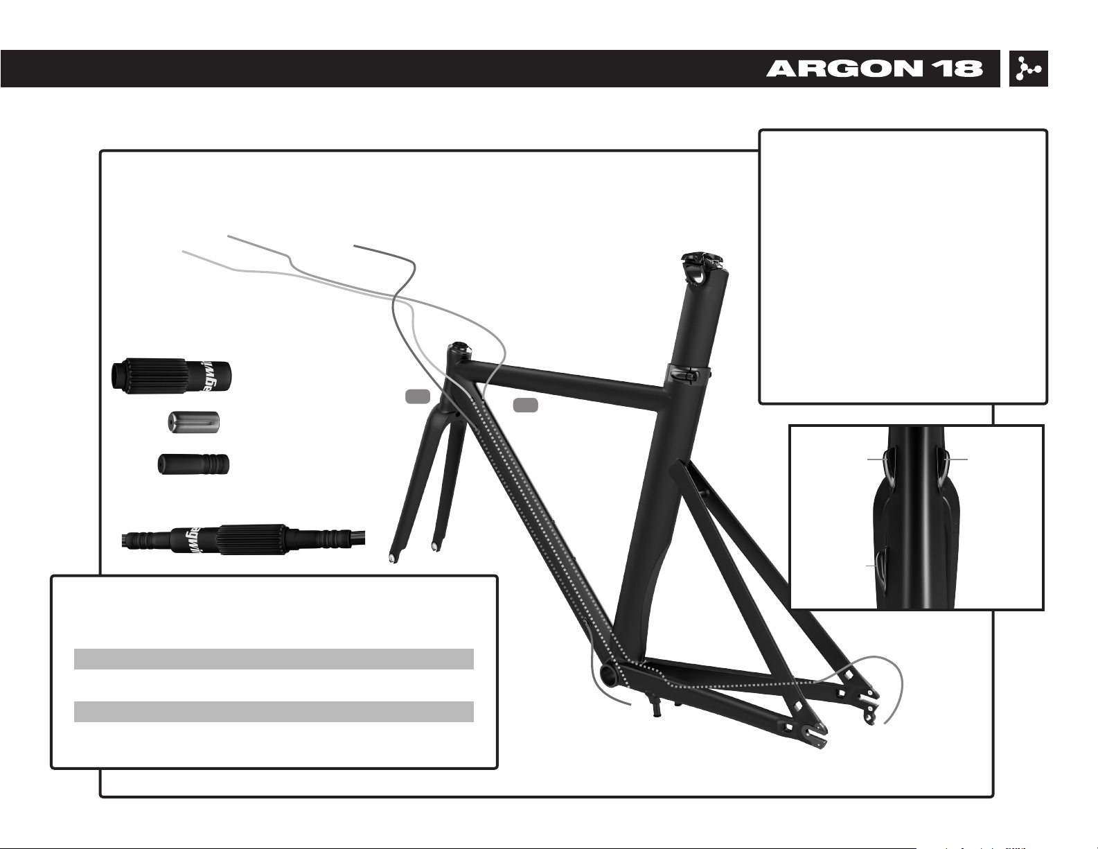
2. Cable housing installation..............................4-7
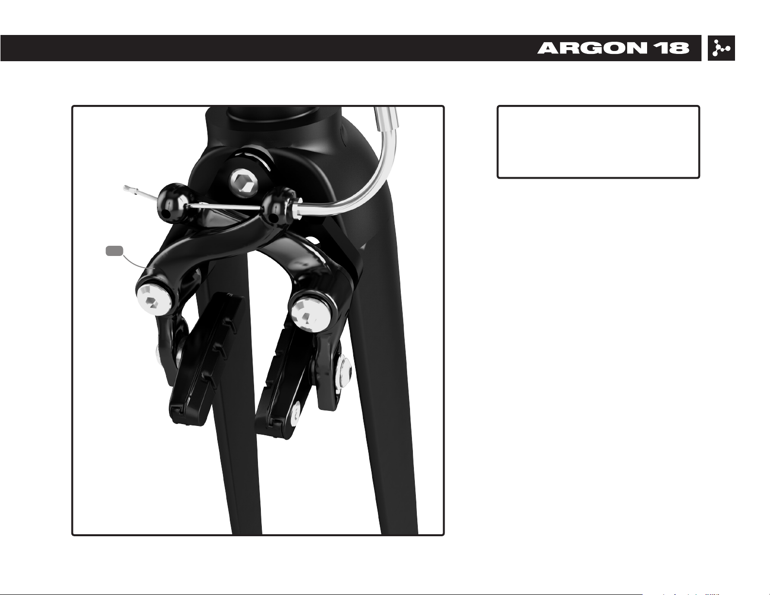
3. Brakes installation .....................................8-9
4. Seatpost installation ....................................10
5. Saddle adjustment .................................. 11-12
6. Parts’ SKUs and Descriptions ........................ 13-14
For the warranty to be valid, the bicycle must be fully assembled by an authorized Argon 18 dealer. High-end components,
particularly carbon parts, need extra care when assembled. Those components must be installed using a calibrated torque
wrench to make sure every bolt is at the right torque setting to prevent damage.
No more than 30mm of spacer can be place between the stem and the top cap of the 3D system.
And the use of more than 5mm spacer on top of the stem could void the eciency of the compressor.
These practices will automatically cancel any warranty claim against the manufacturer.
E-80 219A: Table of contents

2. Cable housing installation
IMPORTANT NOTICE: It is easier to install the
cables and cable housings before the bearings.
1. Frame inspection 3. Brake installation
2
E-80 219A: Assembly overview
5. Saddle adjustment4. Seatpost installation
Images are for reference only. Proportions are not accurate.
3f
3d
3b
3e
7
3c
42
89
3a
5
6
5a
5f
5b
5c
5d
5e
6. Parts listing

3
E-80 219A: 1. Frame inspection
Parts installed on the frame Description Screw Torque Detail
type Nm
1 Front derailleur hanger Screw (2) 3mm 4Nm Loctite
2 Rear derailleur hanger Screw (4) 3mm 4Nm Loctite
3 Bottle cage Screw (2) 4mm 3Nm Grease
4 Bottom bracket cable guide Screw (2) 5mm 2Nm Grease
When assembling a new frame, be sure to check if the following parts are assembled correctly.

1. Install the front derailleur and the
rear brake housing starting at the top of
the downtube (left side).
2. Install the rear derailleur housing
starting at the top of the downtube
(right side).
For the derailleur and brake housing,
measure a sucient length of housing
to be able to turn the handlebar both
ways correctly.
See the table below for the cable housing
suggested length.
Suggested lengths of the cable housing
housing/size
Front brake
Rear brake
Front derailleur
Rear derailleur
58cm
136cm
140cm
198cm
60cm
138cm
142cm
200cm
62cm
140cm
144cm
202cm
64cm
142cm
146cm
204cm
XS S M L
4
E-80 219A: 2. Cable housing installation
2
1
A: barrel adjuster
B: metal cap
C: plastic cap
C
B
B
C
C
speed adjustment: C+A+C
Rear derailleurFront derailleur
Rear brake
12h

Remove the cable guide (3f) and add
a plastic cap on the front derailleur
housing. Insert the plastic cap and the
rear derailleur housing into the cable
guide, then x the guide to the frame
with the M5 screw.
IMPORTANT NOTICE: It is easier to
install the cable housings before the
crank.
5
E-80 219A: 2. Cable housing installation
3f
GREASE

Fix the front derailleur cable to
the front derailleur. Insert the rear
derailleur housing into the hole near
the bottom bracket until it comes out
next to the right side drop out.
6
E-80 219A: 2. Cable housing installation

For each cable housing, measure a sucient length to be
able to turn the handlebar both ways correctly. This will also
ensure the grommets stay in place correctly.
7
E-80 219A: 2. Cable housing installation

Install the rear brake (8) as shown; the
drive side arm must be placed rst.
Insert the retention spring in the center
tension hole. Screw in the brake bolt
at 8Nm. Finally, place the plastic bolt
covers on their respective sides, follow
the natural curves of the brake design.
IMPORTANT NOTICE: It’s easier to install
the rear brake before the crank.
8
E-80 219A: 3. Brakes installation
8
GREASE
GREASE

The front brake is installed behind the
fork. Use the provided sunken nut to x
the brake caliper to the fork; tighten it
to 8 Nm.
9
E-80 219A: 3. Cable housing installation
9

E-80 219A: 4. Seatpost installation
1. Make sure the clamp (3e) sits
correctly on the seat tube.
2. Insert the seatpost (5) on which
some carbon ber assembly gel has
been applied.
3. Position the seatpost at the desired
height and tighten evenly the two
screws to 6Nm.
10
5
3e
6Nm
GREASE
GREASE
CARBON FIBER
ASSEMBLY
COMPOSITE

E-80 219A: 5. Saddle adjustment
1. Install the saddle on the rocker (5f)
and slightly tighten the rail clamp (5e)
using a ball end hex key.
2. Tighten the upper screw of the rocker
clamp (5a) by keeping a space of 2
to 3mm between the aluminum and
carbon parts.
3. Adjust the angle of the saddle and
tighten the lower bolt of the rocker
clamp (5b).
4. Adjust the saddle oset and nalize
the tightening of the rail clamp (5c).
11
5b
5c
5d
5a
5f
5e
GREASE
8Nm
2-3mm
8Nm
GREASE
GREASE

E-80 219A: 5. Saddle adjustment
The 2waypost ASP-4000 can be ipped
to achieve a triathlon or a road position
(75°/78°).
The seat clamp oset can be set by
ipping the rail clamp (5d) and the
rocker (5f).
Road: -10mm to -15mm
Tri: +10mm to 15mm
12
5f
5f
5d
5d

E-80 219A: 6. Parts’ SKUs and Descriptions
13
32580SP.E80.219A
FK.E80.219A
36618
36853
36458
35900
37831
32593
36404
37834
Images are for reference only. Proportions are not accurate.

E-80 219A: 6. Parts’ SKUs and Descriptions*
14
No. Name Assembled on A18 SKU# Qty
Parts already assembled
Parts
3a Rear Derailleur Hanger (incl. screws) Frame 37831 1
3b Front Derailleur Hanger (incl. screws) Frame 35900 1
3f Cable Guide (incl. screw) Frame 36853 1
1E-80 Frame - - 1
2E-80 Fork - FK.E80.219A 1
5E-80 Seat Post Assembly (ASP-4000) - SP.E80.219A 1
3e Seat Post Clamp Frame 37834 1
4Cable Grommet Frame 36618 6
6 Front Brake Fork 36458 1
7 Rear Brake Frame 36404 1
8 Brake Lever - 32593 1
9 Headset (IS-2 15mm with TH-874-1) Frame 32580 1
*Except for the frame itself, which is not sold as a spare part, all parts can be ordered by referring to their respective SKU number.
Popular Bicycle manuals by other brands

Radio Flyer
Radio Flyer Steer & Stroll Trike manual

Bianchi
Bianchi Reparto Corse Use and maintenance handbook

DOCYKE
DOCYKE L-01 Construction manual

Ecotric
Ecotric Folding Fat Bike Assembly instructions & owner's manual

HP Velotechnik
HP Velotechnik Gekko fx 20 Operating manual and service instructions

Giant
Giant GLORY DH Specifications