Argos FireStar ST User manual

DIN 30665, part 1
Instruction manual
EN
2006/95/EG
2004/108/EG
EN61326,61010
Safety Enhanced
Laboratory Gas Burner

8
9
10
11
16
17
18
15
19 19
18a
4
6
2
5
7
1
7a
3
14
13
12
1 - Function knob
2 - Dual knob: - Gas adjustment
- Air adjustment
3 - LED Standard
4 - LED StartStop
5 - LED Button
6 - LED Burner head HOT / BHC
7 - Burner head
7a - Flame orifice
8 - Connector for foot pedal
9 - Power connector for 9 V DC
10 - Gas inlet R 1/4“ L
(left hand thread)
11 - Holding device for
inoculation loop holder
12 - Burner head screw
13 - Monitor electrode
14 - Ignition electrode
15 - Active nozzle
16 - Nozzle holder for
alternative gas
17 - Cover of the burner
shaft
18 - Retaining screw for
cover of the burner shaft
18a- Position screw for the
cover
19 - Guide slots for
tilt adjustment
2

Read these instructions carefully to familiarize yourself with the product. Please
retain these operating instruction for future reference.
Use
Safety laboratory gas burners for heating and flame sterilizing.
Ideal for use in cleanroom workbenches and laboratory.
All users who have been assigned to use this device must have
read and understood these operating instructions or have been
instructed by an expert user so that this device can be used safely
without causing danger.
WARNING: DO NOT LEAVE THE ACTIVATED LABORATORY
GAS BURNER UNATTENDED!
3

Safety Precautions
•On unpacking the unit, check for possible transportation damages.
Do not operate the unit if damages are visible.
•The device can be dangerous if operated or used in an incorrect
manner by untrained staff.
•An incorrect gas connection may create a hazard.
Observe the installation instructions in the manual.
•Pay attention to your relevant rules for using liquid gas.
•Only use DVGW safety tubings with thread or tubing connectors.
Check the condition of the tube/hose frequently. Depending upon type
of tube/hose, hose clamps are required.
•After use or for any longer period of time without attendance, turn the
main gas supply off and turn off the gas burner at the function knob (1).
•All gas connections must be adequately tightened (left-hand thread).
Check for gas leakage with suitable test equipment. DO NOT seal the
swivel nut on the safety laboratory gas burner (10) with Teflon tape, etc.
•BEFORE using the device carefully check the gas feed tube for leaks.
Check this even if the device has been installed by your distributor. To
do this, carry out all the procedures mentioned in these operating
instructions (see paragraph 1).
•Do not operate the unit near flammable liquids or hazardous materials.
•Unattended operation of the unit is not permissible.
•Do not use the device if there is a smell of gas or if there is a leak.
•In the event that gas can be smelled: immediately turn off the gas
supply to the device. Extinguish any open flames. Pull out the mains
plug. Check all gas connections for gas proofness. If the smell of gas
persists, the appropriate authorities must be notified (janitor, gas
utility company, Fire Department).
LEAKING GAS CAN CAUSE A FIRE OR AN EXPLOSION. THIS MAY
RESULT IN SEVERE INJURIES, FATAL ACCIDENTS AND DAMAGE TO
PROPERTY.
4

•NEVER use a open flame to look for leaks.
•Do not smoke if you are searching for leaks.
•NEVER try to loosen or unfasten gas connections while the gas supply
is turned on and the device is in operation.
•Do not store spare or unconnected gas cartridges / gas bottles in the
vicinity of this device.
•Even in an apparently empty gas cartridge/gas bottle, some gas may
still remain. Gas cartridges/gas bottles should be transported and
stored accordingly. Empty gas cartridges should be properly disposed.
•Always work in a well-ventilated area.
•When working with this device, always wear protective glasses.
•Do not allow anything to fall into the flame orifice (7a).
•Keep hands or other parts of the body away from the burner orifice (7a).
•Note that the burner head (7) remains hot after the flame has been
extinguished. Do not touch. Can cause burns.
•Allow sufficient time for burner head (7a) to cool down prior to
cleaning, desinfecting, servicing or transport. Ensure that the
unit and the gas supply are turned off.
•Because of the connectors at the back of the unit the backside should
not be sterilized with a flame.
•Allow sufficient time for burner head (7) to cool down prior to
disassembling.
•Operate the unit with assembled burner head (7) only.
•After cleaning the burner head (7) allow sufficient time to dry before
assembling again.
•Before mounting a nozzle check the O-Ring (20). Replace the O-Ring
if damaged or worn (see paragraph 1).
5

The range: FireStar ST Cat. No.: FST100
with foot pedal (26)
3 standard-programs for button (function knob) and foot pedal
SCS (Safety Control System)
BHC (Burner Head Control)
Removable and decomposable burner head
Tilt mechanism, right / left (23)
Holding device for 3 inoculation loop holders (11)
Nozzles for natural gas, propane/butane gas
Turbo flame
Wrench 17 mm (21) for gas connection
Screwdriver (22) for burner head and
cover of the burner shaft
Tubing connector with swivel nut (24)
Power connection, global (25)
Instruction manual and 2-year warranty
1. Setup Procedure:
The unit is shipped with the nozzle for natural gas N (08) installed.
The nozzle must be changed if other gas is to be used.
Replacement procedure: Remove the Nozzle P (06) from the nozzle
holder (16) with a coin or the edge of the wrench (21) by turning it
counterclockwise. Remove the active Nozzle N (08) for natural gas
(15) in the same way and exchange the nozzles.
ATTENTION: Before mounting a nozzle check the O-Ring (20).
Replace the sealing if damaged or worn (Cat. No. FST8.000.010).
Now you are ready to connect the gas supply to the gas inlet (10).
The correct pressure for natural gas is within the range of 18 - 25 mbar,
for propane/butane gas 28 - 57 mbar.
Only use DVGW or other gas approved safety tubings with thread
or tubing connectors (24). Check the condition of the tube/hose
frequently. Depending upon type of tube/hose, hose
clamps are required.
All gas connections must be adequately tightened with
the wrench (21) (SW 17mm, included). Ensure the system
is free from gas leaks with a suitable test fluid / equipment.
Do not seal up the included tubing connector (24) and swivel
nut with Teflon tape etc.
A DVGW-proven or other gas approved pressure
regulator (50mbar) must be used for liquid gas.
Pay attention to your relevant rules for using liquid gas.
1.1 Foot pedal connection:
Insert the connection cable of the foot pedal into the
socket (8) at the back of the unit.
Note: The LEDs Standard (3) and Start-Stop (4) will flash alternately until a foot pedal has
been connected to the foot pedal socket (8).
20
10
89
16
15
6
21 2223
24
25
26
11

1.2 Electrical connection:
Plug the power cable into the socket (9) on the back of the unit or into the socket on the foot
pedal. The mains power supply unit included is designed for a voltage from 100 - 240 V, 50/
60 Hz. The mains power supply unit may only be connected if these values comply with the
intended electricity supply. Before using it, push the corresponding socket adapter onto the
mains power supply plug (see „Instruction manual Power adapter”, page 14).
2. Operation: Flame regulation
The flame can be varied in size and intensity by turning the gas / air knob (2). Regulating
the size of the flame is done by turning the gas / air adjustment. Regulating the air intake
for the flame intensity is carried out by pulling outwards and at the same time rotating the
gas / air adjustment.
When using for the first time or changing the gas type, turn the gas adjustment
knob two revolutions to the left. Then pull the gas / air adjustment outwards
and simultaneously turn it one revolution to the left to open the air intake.
2.1 Operation: On-Off switch, operating mode
Switch the unit on by a short push on the function knob (1). It can be turned off by a long push
( 2 seconds +) on the function knob. By turning the function knob (1) the foot pedal operating
modes “Standard“ and “StartStop“ or the operating mode “Button“ can be choosen. The
corresponding LED lights up.
2.2 Operation: Application programs
- BUTTON StartStop: The flame is ignited by operation of the function knob (1). The flame
is extinguished after renewed actuation of the function knob (1). Additionally the flame is
automatically extinguished when the burning timer has expired after 60 min.
- PEDAL Standard:
The flame is ignited by operation of the foot pedal. The foot pedal remains depressed for the
duration of use. The flame is extinguished upon release of the pedal.
- PEDAL Start-Stop:
The flame is ignited by operation of the foot pedal. The flame is extinguished after renewed
actuation of the foot pedal. Additionally the flame is automatically extinguished when the
burning timer has expired after 60 min. Alternatively the flame can be extinguished by a short
push on the function knob.
Note: The LEDs Standard (3) and Start-Stop (4) will flash alternately until a foot pedal has
been connected to the foot pedal socket (8). Without foot pedal, operation is possible with
application program BUTTON StartStop only.
2.3 Operation: Switch-off
The unit can be turned off by pushing the function knob (1) for more than 2 seconds.
3. Safety symbols and safety functions:
- Residual heat display: LED “Burner head HOT / BHC“ indicates a hot burner head.
Attention: If the LED “burner head HOT / BHC“ lights up DO NOT TOUCH the burner head.
Can cause burns! Even after switching-off the unit the residual heat LED remains on till the
burner head is cooled down.
Notice: Disconnecting the power supply or removing the power cord will clear the residual
heat display even if the burner head is still hot.
7

- BHC: If the burner head is clogged the amber LED “Burner head HOT / BHC“ will flash.
Additionally, if “burner head HOT / BHC“ is flashing, the maximum burning time in the operating
mode “Button“ and Pedal “StartStop“ is limited to 30 seconds (see paragraph 2.2). If burning
times longer than 30 seconds are required in case of a clogged burner head, the operating
mode “Standard“ can be used without time limit.
If “burner head HOT / BHC“ is flashing it is requested to clean the burner head immediately
(see paragraph 5.1).
- Automatic unit switch off: The unit switches itself off automatically after 4 hours if the flame
has not been lit in this period. All indicated malfunctions are automatically switched off after
4 hours, too. For further operation, switch the unit on again.
4. Error displays:
- Ignition failure: Green LED “Button“, “Standard“ or “StartStop“ blinks
2x
This signal appears and indicates a malfunction if the flame fails to ignite after 7 seconds.
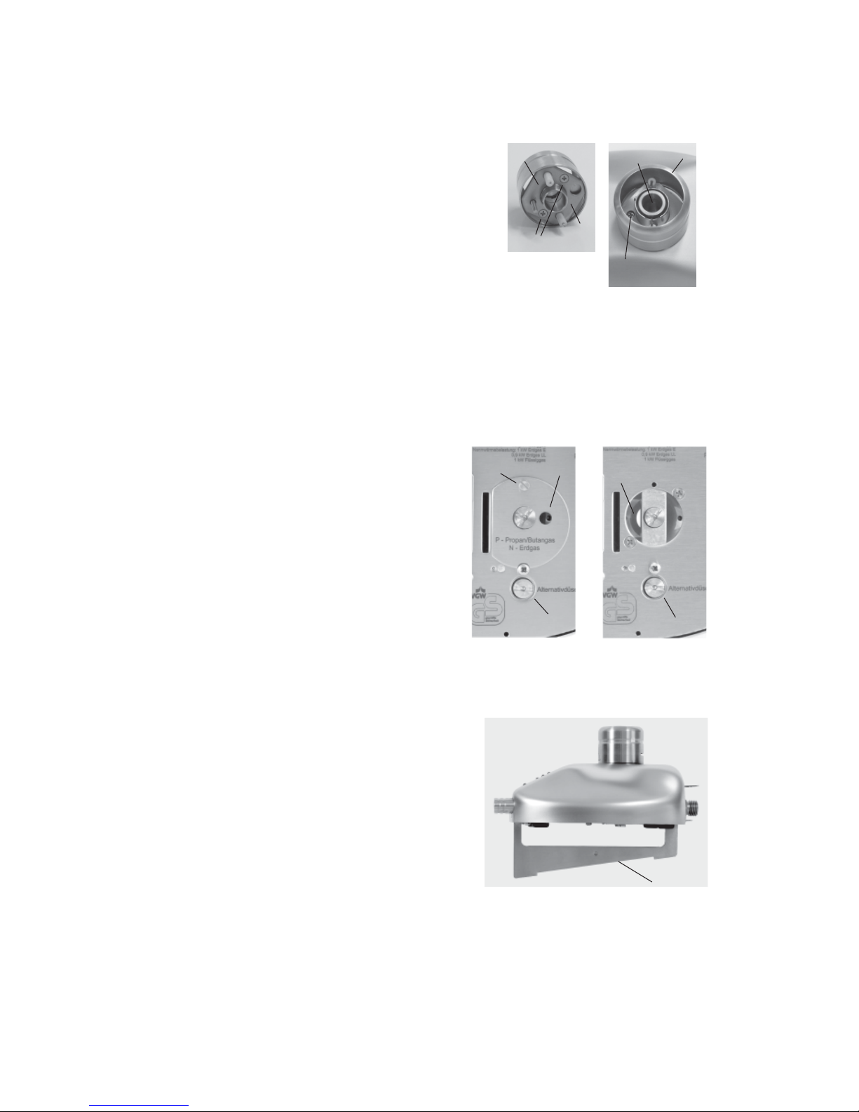
In case of ignition failure check the burner head (7) for possible clogging, check the correct
input pressure of the gas supply and verify that the correct nozzle is installed.
In case of this malfunction the gas supply will be shut off automatically.
Nozzle N (08): natural gas, 18-25 mbar Nozzle P (06): propane-/ butane gas, 47-57 mbar
- Flame failure: Green LED “Button“, “Standard“ or “StartStop“ blinks
3x
This signal indicates a malfunction if the flame is extinguished by external factors and fails
to reignite within 5 sec. In case of flame failure check the burner head (7) for possible clogging
and verify the correct input pressure of the gas supply.
In case of this malfunction the gas supply will be shut off automatically.
- Overtemperature: Green LED “Button“, “Standard“ or “StartStop“ blinks
4x
This signal indicates a malfunction if the interior temperature has exceeded 70 °C. At a normal
room temperature with normal air circulation the unit is suited for continuous operation.
In case of overtemperature increase the air ventilation or change the operation site.
In case of this malfunction the gas supply will be shut off automatically.
- Burner head assembly monitor:Green LED “Button“, “Standard“ or
“StartStop“ blinks
5x
This message indicates that the burner head is removed. Further operation is possible after
the burner head is reinstalled.
- BHC: Amber LED “burner head HOT / BHC“ flashes
This signal indicates that the time limit (30 seconds) is turned on in operating mode “StartStop“
and “Button“ due to a clogged burner head. For cleaning the burner head see paragraph 5.1.
Notice: All error displays can be reset by a long push (2 seconds+) on the function knob (1).
(In case of overtemperature the unit needs to be cooled down and in case of burner head
assembly monitor the burner head needs to be reinstalled prior a reset is possible.)
5. Cleaning and sterilizing:
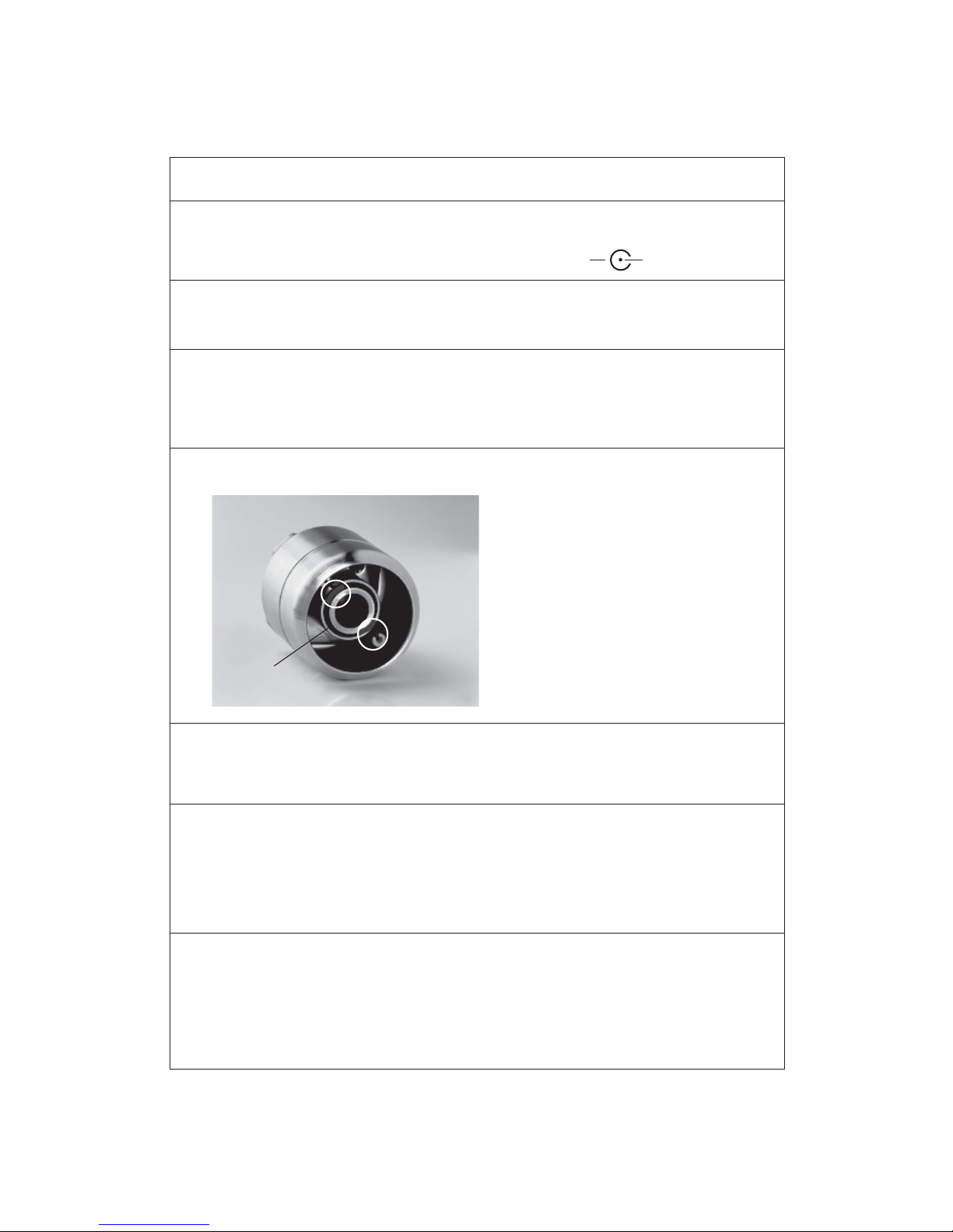
Allow sufficient time for burner orifice (7, 7a) to cool down before disassembling or cleaning
the burner head. Check the unit is disconnected and that the gas supply is turned off at the
mains. The burner can be cleaned with customary commercial disinfectants. Additionally, it
is possible to remove the burner head and to clean it separately.
The stainless steel and glass construction allow 100% UV-radiation sterilization and short
time surface flame sterilization.
Attention: Because of the connectors at the back of the unit the backside should not be
sterilized with a flame.
8

5.1 Burner head disassembly and cleaning:
Allow sufficient time for burner orifice (7,7a) to cool
down before disassembling or cleaning the burner
head. Check the unit is turned off, that the gas supply
is turned off at the mains. Clean the burner head with
customary commercial disinfectants, sterilize it in
an autoclave or wash it in a dishwasher. To remove
the burner head proceed as follows:
Unscrew the burner head screw (12) completely with
the included screwdriver. Turn approx. 8 revolutions to the left.
Now remove the burner head from the device by pulling it upwards. Reinstallation is
performed in the reverse sequence. The dismounted burner head can be even dismantled
into the individual components for in-depth cleaning: Unscrew both screws (12a) and take
off the base plate (12b) of the burner head which was fixed by the two screws (12a). After the
base plate is removed both electrodes can be pulled out for seperate cleaning. Reinstallation
is performed in the reverse sequence.
Notice: When dismantling the burner head completely the sealing ring placed around the
burner head screw (12) could dropout. Ensure that the sealing ring is placed around the burner
head screw (12) when reassembling.
5.2 Burner shaft cleaning:
Unscrew the screw (18) completely with the
included screwdriver. Take off the cover (17)
of the burner shaft. Now the burner shaft can
be cleaned or solid substances which have
fallen into the unit can be removed.
Reinstallation is performed in the reverse
sequence. Take care that the notch of the
cover fits to the screw (18a).
6. Turbo flame:
If the cover of the burner shaft (17) is removed
the flame is extremely firm and consistent. To
take off the cover of the burner shaft unscrew
the screw (18) completely with the included screwdriver. With an open burner shaft the
intensity of the flame cannot be adjusted by the air knob any longer. During the use of the turbo
flame most of the needed air is taken inside through the open burner shaft. Remounting the
cover of burner shaft. (see paragraph 5.2)
7. Tilt adjustment:
Insert the tilt adjustment (23) into the slots (19)
at the bottom of the unit. The tilt-adjustment can
be used to the left or right side to protect the
burning chamber from contamination when
working with liquids.
8. Warranty:
All FireStar are covered under our two-year
manufacturer warranty against any manufacture
defects in material and workmanship. The
Argos warranty guarantees all FireStar under
normal usage conditions and does not cover any
damages as a direct result of user misuse or/and
abuse. The warranty is void upon any unauthorized
servicing, disassembly or modifications.
23
17
18
18a
open
burner shaft
18a
7a 7
12
12a
12b
12b
9

+-
Bypass
Troubleshooting guide
The green LED “Standard“ or “StartStop“ does not light up
Check for correct connection and specification of the power adapter.
Ensure that the original power adapter is used.
Specifications: 9 V / DC, 1A Polarity:
The foot pedal does not work
Check for correct connection of the foot pedal.
Ensure that the foot pedal socket and plug is not twisted or broken.
No Flame
In case of ignition or flame faliure check if the burner head is clogged. Verify the input
pressure of the used gas. Ensure that the correct nozzle is installed in the unit.
Nozzle N (08): natural gas, input pressure: 18-25 mbar
Nozzle P (06): propane / butane gas, input pressure: 47-57 mbar
LED “Burner head HOT / BHC“ flashes / Inspection of the burner head (clogging)
Take care that there are no liquids or other substances at the Bypass (area between the
inner and the outer ring)
Especially remove substances in the
marked areas at the electrodes. If there
are contaminants in this area, the flame
cannot encircle the electrodes correctly.
Clean this areas with a brush. The
burner head can be cleaned with
customary commercial disinfectants,
or it can be sterilized in an autoclave or
washed in a dishwasher.
In operating mode “Button“ or Pedal “StartStop“ flame burns 30 seconds, only
BHC time limit is active, LED “burner head HOT / BHC“ is flashing. The burner head is
clogged and must be cleaned (see paragraph 3 and 5.1).
Flame too small / large / soft
Check the position of the air and gas adjustment.
Check if the correct nozzle is installed.
Nozzle N (08): natural gas, 18-25 mbar
Nozzle P (06): propane / butane gas, 47-57 mbar
Check if the drilling of the active nozzle is blocked. Unscew the active nozzle.
(see paragraph 1) If the drillig is blocked clean with a brush or compressed air.
No ignition spark / LED “Burner head HOT / BHC“ flashes but the burner head is clean
Check if the ceramic electrodes are in good condition. In some cases the electrodes
may break. To check move the ends of the electrodes. If they are not moving they
should be okay. If they are moving more than 0.5 mm the electrodes are broken. The
electrodes can be dismantled and changed by the user. (see paragraph 5.1)
10

The burner shuts-off due to overtemperature frequently
In case of overtemperature increase the air ventilation or change the operation site.
Green LED “Button“, “Standard“ or „StartStop“ blinks 2x
Ignition failure (see paragraph 4)
Green LED “Button“, “Standard“ or „StartStop“ blinks 3x
Flame failure (see paragraph 4)
Green LED “Button“, “Standard“ or „StartStop“ blinks 4x
Overtemperature (see paragraph 4)
Green LED “Button“, “Standard“ or „StartStop“ blinks
5x
This message indicates that the burner head is removed or not mounted correctly.
Reinstall burner head and reset the unit by a long push on the function knob (1)
(see paragraph 4).
Amber LED “Burner head HOT / BHC“ is on permanently
Residual heat display is active. Attention: DO NOT TOUCH the burner head
(see paragraph 3).
11

12
Notes

Technical data:
Technology Microprocessor
Programs
Foot pedal: Standard (flame during pressed foot pedal)
Start-Stop with timer, 60 min
Button: Start-Stop with timer, 60 min
Safety features
Safety Control System (SCS): ignition and flame control, temperature monitor
with gas safety cut off burner head clogging and
assembly monitor (BHC)
automatic unit switch off, 4h
residual heat display
Gas supply and consumtion
Gas supply: 1/4“ left + filter
Gas types: natual gas E/LL,18 - 25
mbar
liquid gas II2ELL3B/P, 20 - 50
mbar
Connected load: 70 g/h liquid gas
Continuous cartridge operation: CV 360 - 40
min, Express 444 - 50
min,
CG
1750 -
150
min, C 206 - 170
min,
CP 250 - 210
min, CV 470 - 370min
Temperatures
Flame temperature: 1350 °C on liquid gas
1300 °C on natural gas (E)
Temperature threshold level: 1 kW liquid gas, 1 kW natural gas
Electrical
Power consumption: 2 VA
Power connection: 100 - 240 V / 50/60 Hz / max. 0.3 A
9 V DC / 1 A
Mechanical
Casing and operating controls: stainless steel / glass, UV and solvent resistant
Burner head: removable and decomposable, stainless steel
Cover of the burner shaft: Ø 23 mm, with drains
Measurements (B x H x T): 103 x 49 x 130 mm
Weight: 700 g
Licences
DIN-DVGW Reg.-No.: NG-2211AS0167
CE: EN 61326-1, EN 61010-1
EEC guidelines: 2004/108/EC and 2006/95/EC
13

Instruction manual Power Adapter
The range
1
2
34
AC plugs
1-EU
2-US
3 - AUS
4 - UK
Removel
5
1. Push the release lever (5) down in direction (a)
2. Push the adapter in direction (b) and remove.
b
a
14

Assembling
1. Select a socket adapter (1-4) suitable for the area of application.
2. Fit the counterpiece on the adapter (7) into the groove (6) and press
in direction (c).
3. Push the adapter in direction (d) until you hear its slot into place.
15
d
c
7
6

Notes
01/12
Argos Technologies
1551 South Scottsdale Court
Suite 200
Elgin, IL 60123
Phone:
GeneralTelephone: 1-800-886-8675 (USA Only)
Local& International: 847-622-0456
Fax: 847-622-0454
Email: [email protected]
Web: www.argos-tech.com
This manual suits for next models
1
Table of contents
Other Argos Laboratory Equipment manuals
Popular Laboratory Equipment manuals by other brands

Blue-White
Blue-White CHEM-FEED C-1100E operating manual

Applied Biosystems
Applied Biosystems GeneAmp PCR System 9600 user manual

CPS
CPS CPS- UVC-19-SW-PPE quick guide

TSI Instruments
TSI Instruments 3775 Operation and service manual

Intellinet
Intellinet 524179 reference guide

Civco
Civco AccuCARE EX3 Stepper reference guide

Leica BIOSYSTEMS
Leica BIOSYSTEMS Aperio AT2 DX user guide

Labconco
Labconco Purifier Logic+ 30348 user manual

GENOMICA
GENOMICA Autoclart Plus user manual

Arctiko
Arctiko Integraline ULUF P10 operating instructions

Metrohm
Metrohm 940 Professional IC Vario Series manual

Oxford Instruments
Oxford Instruments Andor Balor Hardware guide