MILESTONES OF THE INSTALLATION
WELCOME!
1.
2.
3.
4.
5.
6.
7.
8.
• All-in-One ParkIT camera pre-assembled with Ethernet and Power/
Trigger/Serial cables and wall mountable bracket in an IP65 class
weatherproof housing:
Connect and x the wires you intend to use and seal the rest before connecting to power to avoid
damages due to short circuit.
+12V .............................................
GND ...................................................
Opto_out_G (-)** ...............................
Opto_out_S(+)**................................
Opto_in_S (+)* ...............................
Opto_in_G (-)* .............................
NC (no connect)...........................
Serial_RX*** .......................................
Serial_TX***.........................................
Serial_GND*** ...............................
Red
Black
Red
Grey
Brown
Orange
Yellow
Green
White
Blue
2.1 Power/Trigger/Serial Cable Connection
DC
POWER SPECIFICATIONS:
DC input: 12V nominal (11V..15V), reverse polarity protected
Power: 14W
Input current: 1.1A (Max 2.5A transients occur for a few μsecs)
Over-current protection: by fuse
TRIGGER SPECIFICATIONS:
Logic output: Open Collector (max. 12VDC / max. 10mA)
Input: min. 5V, max. 12V
Pulse width: min. 1 ms
See ParkIT Install Guide for sample wiring schematic.
SERIAL CONNECTION:
The serial port of the camera complies with the RS232 standard.
ETHERNET CONNECTION:
The camera is equipped with a CAT5e UTP crossover cable with RJ45 plug. The length of the cable
can be extended with e.g. an inline coupler.
- WVGA B&W or 1.3MP color camera equipped with IR cut/all pass lter
- Remote zoom, focus and iris
- Built-in infrared illuminator unit with four high-power SMD LEDs
synchronized with the camera, adjustable illumination intensity
• LetUgo Install Disc
• USB Hardware Key
• Printed Quick Install Poster
1. MILESTONE: All contents are found: Camera, USB key, Install Disc, Quick Install Guide.
2. MILESTONE: After connecting the power input of the camera, the red and the green status
LEDs of the camera emit light. After the booting sequence,
the red status LED turns o.
• Failures due to improper cabling void the warranty!
• Avoid accidental contacting of the end sleeves. It may cause permanent damages.
• Protect camera cable ends from moisture! Water may enter into the camera inside through loose cable ends.
• Do not bend the cables sharply.
• Consider voltage drop if you use long cables.
• The serial port of the camera complies with the RS232 standard.
* For trigger input: ** For trigger output: *** General-purpose serial port:
Opto_in_S (+) – GPIO Input
Opto_in_G (-) – GPIO Input
Opto_out_G (-) – GPIO Output
Opto_out_S (+) – GPIO Output
Serial_RX
Serial_TX
Serial_GND
Open the Box and Check Package Contents
Connect the Camera Wires
ARH Inc.
1.
2.
20 px
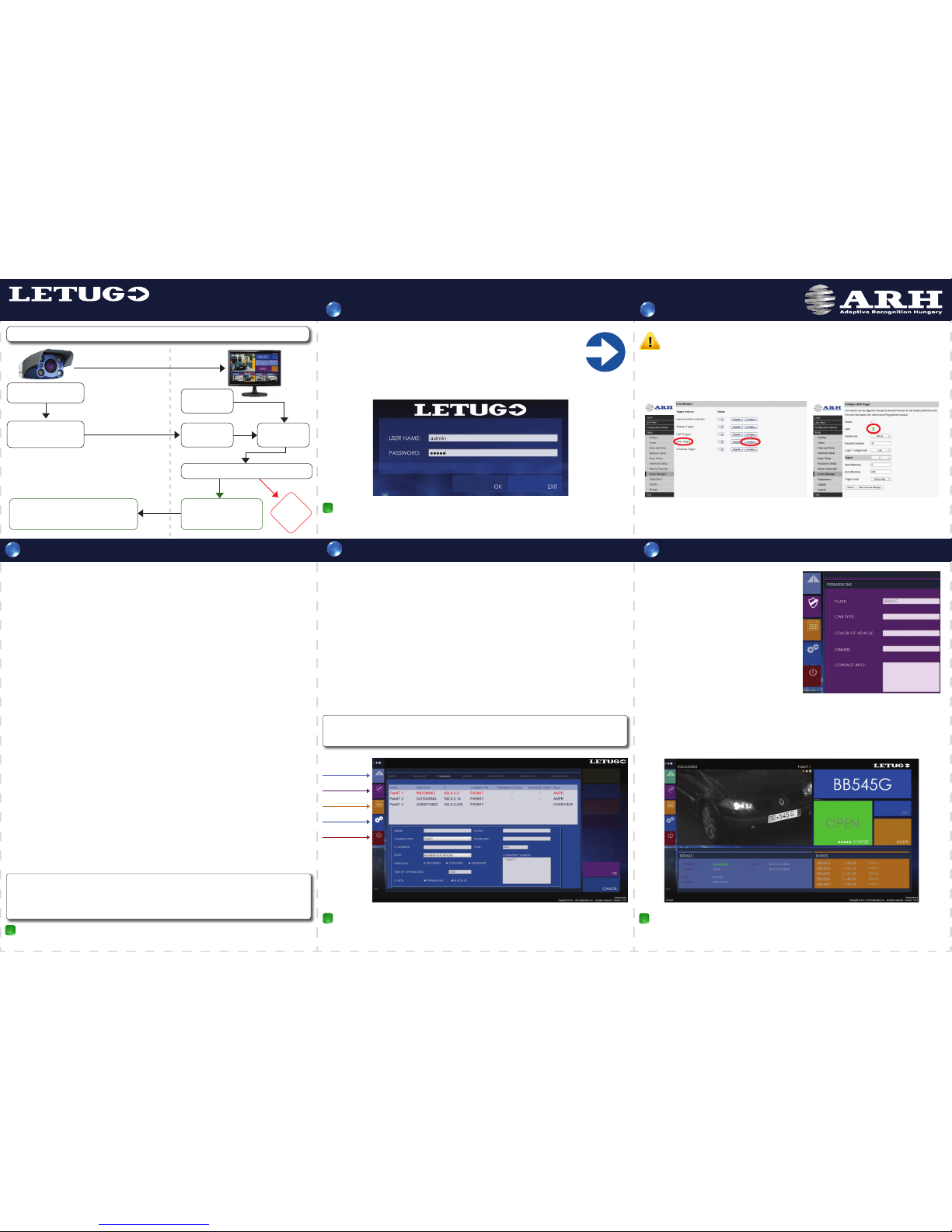
3. MILESTONE:
4. MILESTONE: The live image of the camera shows a clear, sharp and easily readable license
plate, similarly to the screenshot above.
3/1: The ping package returns from the ParkIT camera (192.0.2.3).
3/2: The live image of the camera can be seen through the browser.
Access the Camera
Congure the Camera
3.1 Software Requirements of the ParkIT Camera
• For network setup, administrator (root) privileges are necessary.
• Web browser: Mozilla Firefox 4, Internet Explorer 8, Google Chrome 14.X.X.X or later editions
Use either a real license plate (suggested) or the printed copy of the attached image (pdf) located in
the RESOURCES\Plates folder to setup the camera (A3 size is recommended). Place the license plate
at a distance between 3-12 meters in front of the camera.
The camera can be congured in three dierent ways
detailed below.
At the rst occasion, using the Easy Setup is suggested.
NOTE: Zoom settings are optimal if the character height on
the camera image is at least 20 pixel (see gure).
1. Manual conguration - Using the Easy Setup
Find the Easy Setup option in the ‘Setup’ menu of the camera’s webpage.
After adjusting the zoom, the camera can be ne-tuned by changing the ash intensity,
brightness and focus.
2. Automatic conguration - Using the Conguration Wizard
Follow the steps of the Wizard to complete the conguration process.
For more information on the steps of the Wizard, refer to the ParkIT User’s Manual.
3. Advanced manual conguration - Using the Advanced Setup
Find the Advanced Setup page in the ‘Setup’ menu. Each parameter can be adjusted individually.
For more information on the advanced setup, see ParkIT User’s Manual.
3.2 Steps of accessing the web interface of the camera from a browser:
1. Connect the camera to a computer or network switch then power on
the camera. After it is powered on, both status LEDs (red and green on the
camera front) are turned on while the camera is booting and calibrating the
optics. After nished, the green status LED ashes two times while the red
one turns o signaling that the camera is ready for operation.
2. Set your computer’s IP address (or enter an alternate IP) in the 192.0.2.x
subnet where x is an integer number between 1 and 254 except 3 and your
subnet mask to 255.255.255.0 (for more information use your operating system’s help).
3. Use the ping command in your operating system’s command line to test the communication with
the camera: ping -t 192.0.2.3
4. Soon, the ping package returns: Reply from 192.0.2.3.If not, power o then on and enter
the previous ping command again.
5. Start a browser then enter the default IP address (192.0.2.3) of the camera into the address bar and
hit enter. After this, the camera starts with administrator privileges, ready to be set up and congured.
3.
4.
CAUTION
ParkIT & LetUgo Install Guide – Installing the ParkIT Camera
Technical specications are subject to change without prior notice!
Connection Diagram
Power
Trigger
Serial
Ethernet
All contents are found.
After connecting the power input of the camera, the red and the green status LEDs
of the camera emit light. After the booting sequence, the red status LED turns o.
3/1 The ping package returns from the ParkIT camera (192.0.2.3).
3/2 The live image of the camera can be seen through the web browser.
The live image of the camera shows a clear, sharp and easily readable license plate,
similarly to the screenshot in step 4.
LetUgo installation has nished successfully.
6/1 The USB dongle is connected and the driver is installed.
6/2 LetUgo can be launched from the Start Menu. User Admin has logged in successfully.
Camera(s) has(have) been added successfully. The live image of the camera can be seen
by clicking on the ‘Lane’ menu icon on the top-left corner of the screen.
Check the trigger settings by placing the license plate properly in front of the camera and
clicking on the ‘Open’ button. The LetUgo executes ANPR and returns the plate text on
the top-right corner.
• Unpack the camera on soft ground to avoid scratching the hardware.
• Make sure that the package is lying on a at and solid surface.
• Install the camera only in dry environment, within the storing temperature range of the camera:
-35ºC to +55ºC (-31º F to 131º F).
• Do not leave the camera disconnected from power for longer periods to protect its internal battery feeding
the camera RTC (Real Time Clock). This battery can keep the RTC settings for approx. one year and cannot be
recharged but replaced by the manufacturer only.
• Never use the camera without its sunshield.
• Avoid scratching the camera front during unpacking.
• Read the ParkIT Install Guide for details of installation.
Web interface after conguring the camera
• To enable all camera functions, enable (and update) JavaScript and ActiveX controls in your browser.
• Changing the default IP address of the camera is recommended
(Setup/Network Setup/IPv4 settings or IPv6 settings/IP address) – especially if more ARH cameras are used in the same
network – to avoid IP address conict.
• To alter the IP address of your computer, administrator privileges are necessary.
• Power on the camera only if the ambient temperature is higher than the camera’s startup temperature of -20ºC (-4ºF).
Welcome to the Quick Start Guide of the ParkIT ANPR Camera with the LetUgo Access Control
Software! This document is intended to guide you through the installation steps and to help to setup
your ANPR system quickly and easily.
NOTE: This Quick Install Guide contains only a short description of the main installation steps.
For complete understanding of the installation process, refer to the following manuals:
• ParkIT Install Guide and ParkIT User’s Manual ([HELP] button on the ParkIT Camera web interface)
• LetUgo User’s Manual ([HELP] button on the LetUgo user interface).
In order to make the installation easy to follow, the entire process is divided by so-called MILESTONES
that serve as checkpoints and are located after every signicant step. These MILESTONES help users by
providing them feedback that the installation is proceeding well. Use the table to follow the completed
MILESTONES: