Hootoo HT-IP006N Product guide

HT-IP006N
Manual Book

Security Solutions Partner
2
CONTENTS
1 WELCOME........................................................................................................................................................................ 3
1.1 FEATURES..................................................................................................................................................................................................3
1.2 PACKING LIST........................................................................................................................................................................................... 3
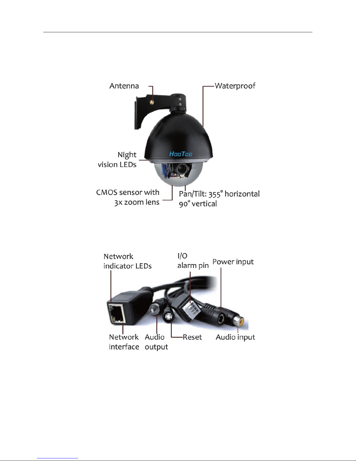
1.3 PRODUCT VIEWS....................................................................................................................................................................................... 4
1.4 PC SYSTEM REQUIREMENTS..................................................................................................................................................................... 5
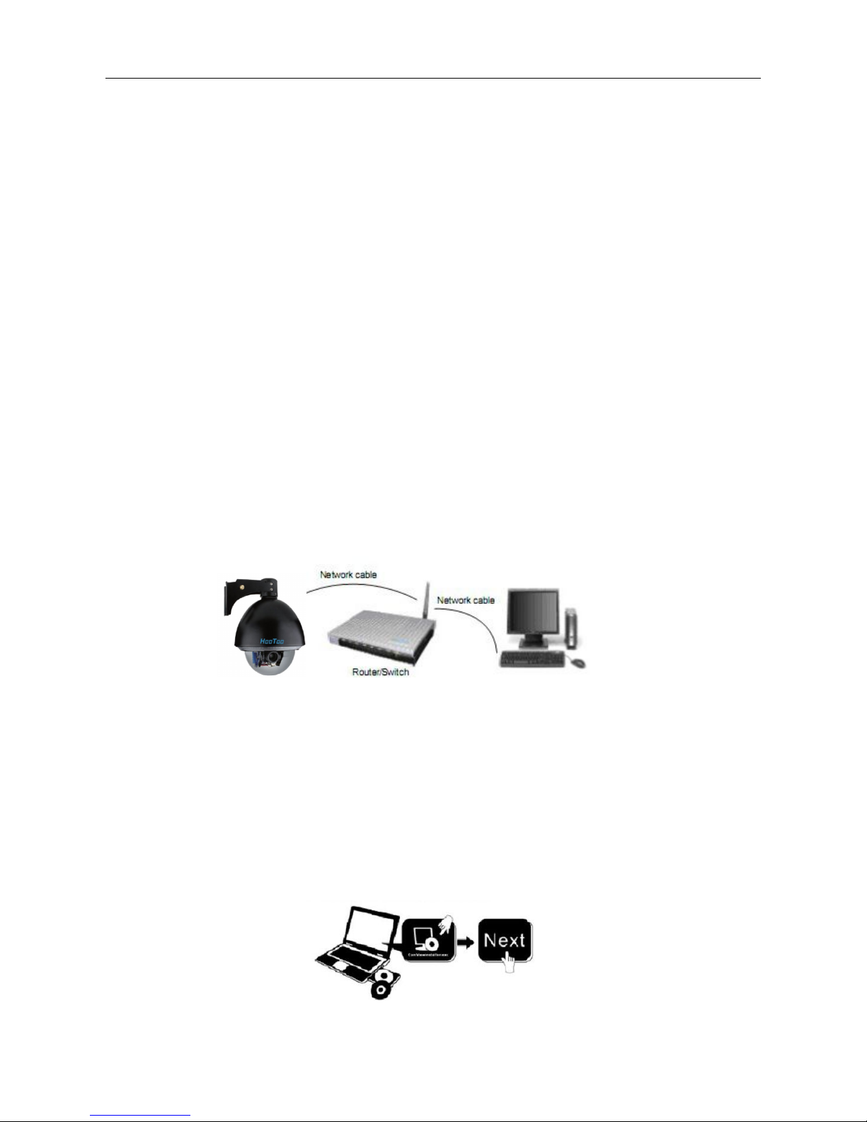
1.5 HARDWARE INSTRUCTION......................................................................................................................................................................... 5
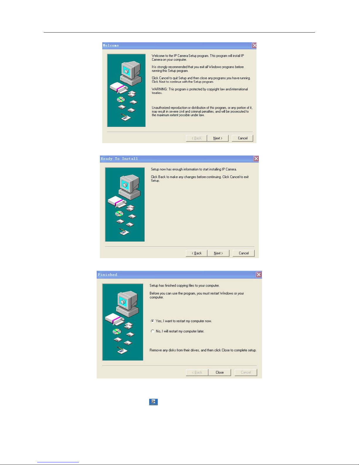
1.6 SOFTWARE INSTALLATION.........................................................................................................................................................................5
2. SOFTWARE OPERATION.............................................................................................................................................7
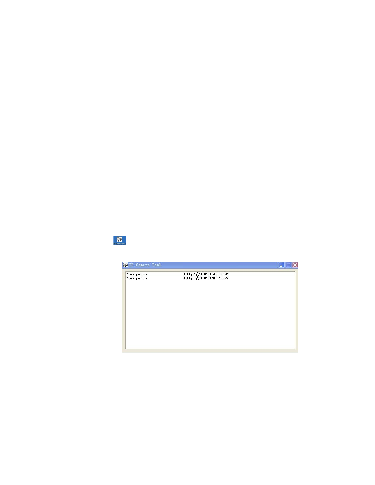
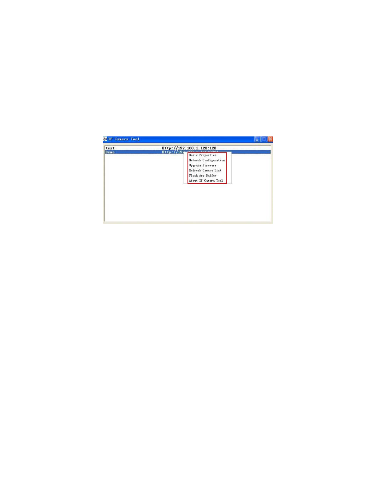
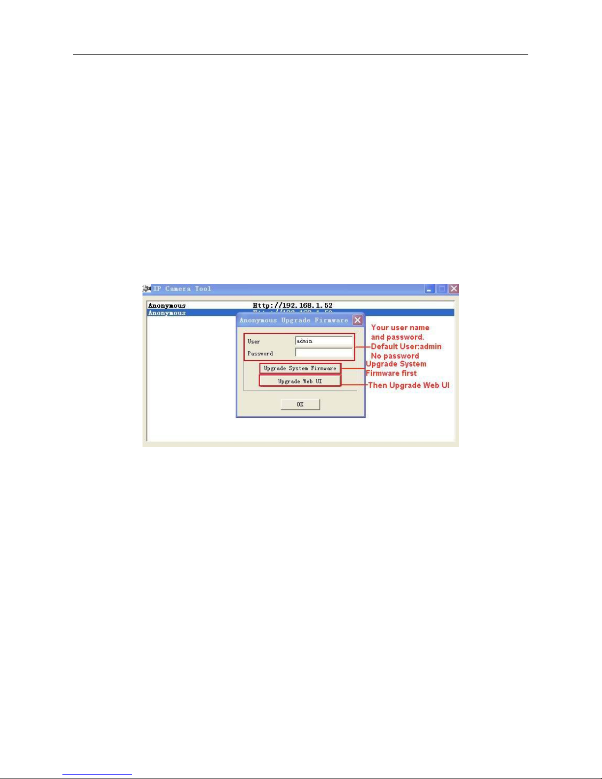
2.1 IP CAMERA TOOL...................................................................................................................................................................................... 7
2.2 CAMERA LOGIN.......................................................................................................................................................................................11
2.3 FOR IE BROWSER....................................................................................................................................................................................12
2.4 FOR SAFARI, FIREFOX, GOOGLE BROWSER............................................................................................................................................ 15
2.5 FOR MOBILE PHONE............................................................................................................................................................................... 16
2.6 ACTIVEX MODE (FOR IE BROWSER)...................................................................................................................................................... 16
2.7 FOR VISITOR............................................................................................................................................................................................16
2.8 FOR OPERATOR....................................................................................................................................................................................... 20
2.9 FOR ADMINISTRATOR.............................................................................................................................................................................. 22
3 Settings as Administrator.......................................................................................................................................... 22
3.1 MULTI-DEVICE SETTINGS........................................................................................................................................................................23
3.2 NETWORK SETTINGS................................................................................................................................................................................28
3.3 BASIC NETWORK SETTINGS.....................................................................................................................................................................28
3.4 WIRELESS LAN SETTINGS....................................................................................................................................................................... 30
3.5 ADSL SETTINGS......................................................................................................................................................................................32
3.6 UPNP SETTINGS...................................................................................................................................................................................... 32
3.7 DDNS SERVICE SETTINGS...................................................................................................................................................................... 32
3.8 SYSTEM SETTINGS...................................................................................................................................................................................36
3.9 ALIAS SETTINGS......................................................................................................................................................................................37
3.10 DATE &TIME SETTINGS.........................................................................................................................................................................37
3.11 USERS SETTINGS................................................................................................................................................................................... 38
3.12 PTZ SETTINGS.......................................................................................................................................................................................39
3.13 INDICATOR SETTINGS............................................................................................................................................................................ 39
3.14 BACKUP & RESTORE............................................................................................................................................................................. 39
3.15 OTHER SETTINGS.................................................................................................................................................................................. 41
3.16 MAIL SERVICE SETTINGS...................................................................................................................................................................... 41
3.17 FTP SERVICE SETTINGS........................................................................................................................................................................ 43
3.18 ALARM SERVICE SETTINGS................................................................................................................................................................... 44
3.19 SEND MAIL ON ALARM......................................................................................................................................................................... 47
3.20 PATH SETTINGS.....................................................................................................................................................................................49
3.21 SERVER PUSH MODE (FOR SAFARI, FIREFOX, GOOGLE BROWSER).....................................................................................................50
3.22 SIGN IN MOBILE PHONE.........................................................................................................................................................................50
4. APPENDIX..................................................................................................................................................................... 51
4.1 FREQUENTLY ASKED QUESTIONS............................................................................................................................................................51
4.2 DEFAULT PARAMETERS...........................................................................................................................................................................54
5. Specifications...............................................................................................................................................................54
6. CONTACTING TECHNICAL SUPPORT.................................................................................................................. 55

Security Solutions Partner
3
1 WELCOME
This is an integrated wireless IP Camera. It combines a high quality digital Video Camera with network
features and a powerful web server. You can access this camera from anywhere on your local network or over
the Internet.
The basic function is transmitting remote video on your IP network. The high quality video images can be
transmitted with 30fps speed on the LAN/WAN by using MJPEG hardware compression technology.
It is based on TCP/IP standard, built-in WEB server which is supported by Internet Explorer. The management
and maintenance of your device is simply accessed by using a network to achieve the remote configuration,
start-up and upgraded firmware.
You can use this IP Camera to monitor locations such as your home and your office. Controlling and managing
images are simply done by accessing the website through the network.
1.1 Features
☆Powerful high-speed video protocol processor
☆High-sensitivity 1/4’’ CMOS sensor
☆Picture total 300k pixels
☆Supports 3x Optical Zoom
☆Supports PT control, Pan 355°, Tilt 90°
☆Optimize MJPEG video compression for transmission
☆Multi-level users’ management and passwords definition
☆Embed Web Server for users to visit by IE
☆Supports wireless networks (WI-FI/802.11/b/g)
☆Supports Dynamic IP (DDNS) and UPNP LAN and Internet (ADSL, Cable Modem)
☆Give alarm in cause of motion detection
☆Supports image snapshot
☆Supports multiple protocols: HTTP/TCP/IP/UDP/SMTP/DDNS/SNTP/DHCP/FTP
☆Supports WEP/WPA/WPA2 encryption
☆Supports 3G phone, Smart phone control and surveillance
☆Supports Firefox, Safari, Google chrome browser.
1.2 Packing List
Untie the pack and check the items contained against the following list:
●IP Camera X1
●Wi-Fi Antenna X1
●User Manual X1
●DC Power Supply X1
●CD X1
●Network Cable X1
●Mounting bracket X1
NOTE: Please contact us immediately in case of any damaged or missing contents.

Security Solutions Partner
4
1.3 Product Views
1.3.1 Front View
Figure 1.1
1.3.2 Cable Interface
Figure 1.2
Audio Output: The jack is used to plug external speakers or audio output devices.
Audio Input: The jack is used to plug external microphones or audio input devices.
I/O Alarm Pin: 1 Alarm input (GND), 2 Input, 3 Output A, 4 Output B
Network Interface: RJ-45/10-100 base T
Network indicator: The green LED will be on when the network is connected. The yellow LED will blink
when data is transferred.
Reset: Press and hold the RESET button for about 15 seconds, all the parameters will be back to the factory

Security Solutions Partner
5
default settings. (Please keep the power on when using RESET)
Power: DC 12V/2A power supply
1.4 PC System Requirements
System configuration requirements: (Example for viewing four IPCAM)
CPU: 2.06GHZ or above
Memory: 256M or above
Network Card: 10M or above
Display Card: 64M or above memory
Recommendable Operating System: Windows 2000/ XP/ Vista/ 7
1.5 Hardware Instruction
Follow the steps below to set up your camera hardware. Make sure to follow each step carefully to ensure that
the camera operates properly.
1. Install the Wi-Fi antenna
2. Plug the power adaptor into the camera
3. Plug the network cable into the camera and router/switch
4. It takes approx. 30 seconds to boot up the camera, then you will find the IP address from
“IP Camera Tool” (Figure: 1.8)
5. When the power is on and network cable connected, the green LED of the panel will stay on,
The yellow LED will keep flashing.
Figure1.3
1.6 Software Installation
Attention: For a smoother installation process, we suggest that turn OFF your Firewall and Antivirus before
install the ActiveX, Don’t worry, it is safe.
Install the following software:
1. IP Camera Tool: Open the CD, double click “IPCamSetup.exe”, click next, you will complete the software
installation.(figure1.5/ 1.6/ 1.7)
2. ActiveX: Double click “Appinstall.exe”—“Next”—“Install”—“Finish”.
Figure1.4

Security Solutions Partner
6
Figure1.5
Figure1.6
Figure1.7
After this done, the icon “IP Camera Tool”
will be displayed on your desktop automatically.

Security Solutions Partner
7
CAUTION: Before installing and using the product, please read the following precautions carefully and make
sure they are fully understood.
Use only the power adaptor included with the product. Using unauthorized power adapters may cause
damage to your IP Camera.
IP Camera terminal shall be installed in an indoor environment where there is no rain or snow.
Do not touch the lens of the IP Camera. The optimum focus range has been set before it is delivered out of the
factory. If you turn the lens, it may cause incorrect focus and vague images.
Do not turn the Pan/Tilt by force, it may cause damage to internal components of the Pan/Tilt.
2. SOFTWARE OPERATION
2.1 IP Camera Tool
When the Device has been mounted properly, you can double click the Icon “IP Camera Tool” and a dialog box
as Figure 1.8 will pop up.
Figure1.8
Note: The software searches IP Servers automatically over LAN.
There are 3 cases:
1. No IP Cameras found within LAN. After searching for 1 minute, the Result Field will show “not found IP
Server” and the program will shut down automatically.
2. IP Cameras have been installed within your LAN. All the IP Cameras will be listed and the total number is
displayed in the result field as shown in Figure 1.8
3. The IP Cameras installed within LAN do not share the same subnet with the monitoring PC. A prompt as
shown in result field (prompt: Subnet doesn’t match, double click to change!). Click the left mouse button to

Security Solutions Partner
8
choose the prompt and click the right mouse, choose Network Configuration to set the static IP address of
the Camera to the same subnet as LAN. (Figure 2.2)
NOTE: If it shows” Subnet doesn’t match, double click to change!”, you can also choose ”Obtain IP from
DHCP Server” to get a dynamic IP. (Figure 2.1)
2.1.1 Six Options
Choose the IP Camera list and Click right mouse, there are six options: (Figure 1.9)
Basic Properties,Network Configuration,Upgrade Firmware,
Refresh Camera List,Flush Arp Buffer,About IP Camera Tool.
Figure1.9
2.1.1 .1 Basic Properties
There is some device information in the Basic Properties, such as Device ID, System Firmware Version,
Web UI Version.(Figure 2.0)
The Device ID is the camera’s MAC ID (or Mac Address), which should be the same as showed on the
sticker at the bottom of camera. Every camera has its unique MAC ID.
Sometimes, if there is no IP address shown on the IP Camera tool, it might be blocked by a firewall. Add the
MAC ID to the router, and give it a fixed IP or add the MAC ID as a trusted site. There are two MAC Addresses,
one is Device MAC ID, the other is WIFI MAC ID.
WIFI MAC ID, you can find it from the sticker at the bottom of the camera, if this is sticker lost, you can login
your WIFI router, check the host status, which will show all the WIFI devices connected to this router, you can
also find the IPCAM’s WIFI MAC ID there.

Security Solutions Partner
9
Figure2.0
2.1.1.2 Network Configuration
In this page, you can configure the Network parameter.
Figure2.1
Obtain IP from DHCP server: If clicked, the device will obtain IP from DHCP server. In other words, the
camera will have a dynamic IP. (Make sure the Router which the camera is connected to has DHCP function
and DHCP is enabled).(Figure 2.1)
Figure 2.2
IP address: Fill in the IP address assigned and make sure it is in the same subnet as the Gateway, and the
subnet should be the same as your computer or router. (I.e. the first three sections are the same)
Subnet Mask: The default subnet mask of the equipment is: 255.255.255.0. You can find the subnet mask
from your PC or router.

Security Solutions Partner
10
Gateway: Make sure it is in the same subnet with your PC’s IP address. Gateway is the LAN IP of your router.
DNS Server: IP address of IPS network provider. You can also set it’s the same as the Gateway.
NOTE: You can find the Subnet Mask,Gateway,DNS Server from your router, or check the local connection
status of your computer to get all the parameters. Normally two DNS servers are optional.
Http Port: LAN port assigned for the equipment, default is 80. You could set another port number like 81, 801,
8001 etc.
User: Default administrator username is: admin (all lower-case)
Password: Default password is blank, no password.
NOTE: If the prompt “subnet doesn’t match, double chick to change!” appears, please set the IP Address,
Subnet Mask,Gateway,DNS Server once again, or enable Obtain IP from DHCP server.
2.1.1.3 Upgrade Firmware
Enter the correct Username and Password to upgrade system Firmware and Web UI. If you upgrade the
camera, Please upgrade system firmware first and then upgrade Web UI.(Figure 2.3)
Figure 2.3
Please download the firmware package before upgrade.
Follow the upgrade document in the package carefully to upgrade. Please read over the readme.txt file before
you do upgrade.
CAUTION: Sometimes, your camera may be damaged if not upgrading properly.
If your camera works well with the current firmware, we recommend that you don’t update it.
NOTE: When upgrading, please keep the power on, and use a direct connection with your network cable.
2.1.1.4 Refresh Camera List
Refresh camera list manually.
2.1.1.5 Flush Arp Buffer
When your cable network and wireless network of the device are fixed IP addresses. There is a problem you
may encounter when searching for the camera IP but can’t open the camera web page. You may try to use
Flush Arp Buffer.
2.1.1.6 About IP Camera Tool

Security Solutions Partner
11
Check the IP Camera Tool Version and IP Camera ActiveX Control Version here.
2.2 Camera Login
You can access the camera through IP Camera Tool or IE, Firefox, Safari, Google Chrome or other
browsers.
1. Double click the IP address of the IP Camera listed (Figure 1.8). The default browser you use will run
automatically and open the camera login interface. (Figure 2.6)
2. To access the camera by IE Browser directly, just type the camera’s IP address, for example, if the camera’s
IP address is 192.168.1.123:
Figure 2.4
Figure 2.5
The default user name is admin, no password
Input the correct user name and password, the Sign In interface will pop-up.
There are three modes to login (figure 2.6).

Security Solutions Partner
12
Figure 2.6
(1) Active Mode (For IE Browser): available in IE6.0 or above
(2) “Server Push Mode”: available in Firefox, Safari, and Google Chrome browser.
(3) “Sign in mobile phone”: available for Mobile phones
2.3 For IE Browser
Choose Active Mode (For IE Browser), and sign in.
Figure 2.7
The first time you login to the camera, you might get the ActiveX prompt as the picture above, please click the
prompt and choose Run Add-on, refresh and login the camera again, then you will see live video, shown as
below:

Security Solutions Partner
13
Figure2.8
Figure 2.9
Note: If there is still no live video after running ActiveX, and a red cross shows in the center of the
screen, or even just a black screen, please try to enable the ActiveX options in IE security settings.
Please do the follow steps:
1. Close the firewall on your computer.
2. Change the ActiveX settings, “IE” browser > “Tool” > “Internet Options” > “Security”> “Custom Level” >
“ActiveX control and Plug-ins”, all the ActiveX options set to be “Enable”:
Also:
Enable: Download unsigned ActiveX controls
Enable: Initialize and script ActiveX controls not marked as safe
Enable: Run ActiveX controls and plug-ins

Security Solutions Partner
14
Figure3.0
Figure 3.1
In addition: you can also click “Start” menu->“Internet Explorer”, choose “Internet attributes “ to enter, or via
“Control Panel” ->“Internet Explorer”, enter to Security setting.
If ActiveX is running, but you still could not see live video, please try using another port number. Don’t use port
80, use other ports such as 128, 1008 etc.

Security Solutions Partner
15
Figure 3.2
NOTE: Make sure that the firewall or anti-virus software doesn’t block the software or ActiveX. If you couldn’t
see live video, please close your firewall or anti-virus software, and try again.
2.4 For Safari, Firefox, Google Browser
Choose Server Push Mode (For Safari, Firefox, Google Browser), and sign in
Server Push Mode doesn’t support ActiveX, so some functions are not available, such as Play,Stop,Record,
Audio,Talk etc. if you want to use these functions, please use IE browser.
Figure 3.3

Security Solutions Partner
16
2.5 For Mobile Phone
Choose Sign in mobile phone, and sign in.
Mobile phone doesn’t support ActiveX, only some basic functions can be available in this mode.
It supports most smartphones with a 3G/4G connection. Usually, if the mobile phone supports network video,
then it can work with our IP Camera.
Figure 3.4
2.6 ActiveX Mode (For IE Browser)
Login the camera in ActiveX mode, the main User Interface will be shown as below:
NOTE: There are 3 levels of users, Visitor, Operator, Administrator, if you login with different users, the
features/operations are different. (See 3.11 User Settings, Figure 8.5)
2.7 For Visitor
When logged in as Visitor, you can enter the IP Camera for visitor.
Visitor is the lowest level with only some operations available

Security Solutions Partner
17
Figure 3.5
Channels:
Our IE software supports 9 channels total. Clicking can get different windows.
:Click this one, you can view the main channel of the camera.
:Click this one; you can view 4 Channels of cameras that are connected, from CH1 to CH4.
:Click this one; you can view 9 Channels of cameras that are connected, from CH1 to CH9.
NOTE:If you want to view 4/9 channels, you should set the Multi-Device first (See 3.1 Multi-Device
Settings)
Status of Channels:
There are 9 icons at the bottom of the UI which show the status of each channel of the camera.
:Grey color, means there is no device connected to the main device from this channel.
:Green color, means the device is connected from this channel, and it works well.
:Red color, means the device of this channel is recording.
:Yellow color, means set this channel in multi-device already, but it fails to connect to the main device.

Security Solutions Partner
18
OSD Settings:
Figure 3.6
OSD: Means “On-Screen Display”, click “Audio video” > “OSD”, set display date and time on the video.
Disabled: Click this one, means clear the OSD.
Color: Can set the OSD text color as black, yellow, red, white, blue etc.
Add time stamp on record: Click this, there will be time OSD on record video files.
Figure 3.7

Security Solutions Partner
19
Rate and Resolution:
Rate: Set video framerate here, from “full-speed to 1fp/5s”. (Figure 3.8)
Resolution: Set the resolution to be 160*120/ VGA(640*480)/ QVGA (320*240). (Figure 3.9)
NOTE: When doing recording, Rate and Resolution parameter settings is very helpful for getting small
sized recording files, the lower parameter to get the smaller file.
Figure 3.8 Figure 3.9
TOP Menu:
Figure 4.0
:Click it to get live video. When you want to go back to live video from other menus, just click it.
Only under live video, you can do the operations on the right side, such as play, stop, snapshot etc.
:Click it to get into play mode, when you click stop icon, the video will be stopped, then click
play icon, it will show the video again.
:Click it to stop the live video. You can click the play icon if you want to see live again.
:Click it to get snapshot. It will show the date and time of the snapshot you get, when you want
to save it, you will find the snapshot file named by “snapshot_MAC ID_date_time”.
:Click it to start recording manually, and the icon will change to red color ,click it
again, it will stop recording. The record file will be saved to the folder you set. (Figure 10.8-Figure11.0)
:Click it to hear the sound around the camera, if you plug a earphone or a speaker in the
computer which you are using, you will hear the sound around the camera. This IP Camera has a built-in
microphone, when you click it to start work, the icon will change to red color ,click it again, will stop
the audio function.
:Click it to start the talk function, first you have to plug a microphone in your computer. When
you are talking about something with the microphone from your computer, the sound will come out from the
built-in speaker of the camera, people beside the camera will hear the sound. If you are connected to an
external speaker from the audio output hole at the back of the camera (Figure 1.2), you will get better sound
effects. Click it once, the icon will change to red color ,click it again, will stop talk function.

Security Solutions Partner
20
NOTE: For visitor, if you click other menus which visitor don’t have the right to operate it, there will be a pop-up
of the login interface (Figure 2.6), please input the user name / password for at least 3 times to login again.
2.8 For Operator
When logged in as Operator, you can enter the IP Camera with Operator mode.
For operator, it not only supports all the functions which for Visitor, and also supports these functions as below:
Figure 4.1
Audio Video Settings
Figure 4.2
Audio buffer: Click this icon, it will show five numbers, which means 1/2/3/4/5 seconds’ buffer of audio.
Table of contents
Other Hootoo IP Camera manuals

Hootoo
Hootoo HT-IP211HDP User manual

Hootoo
Hootoo HT-IP212HDP Instruction manual

Hootoo
Hootoo HT-IP210P User manual

Hootoo
Hootoo HT-IP009HDP User manual

Hootoo
Hootoo HT-IP211HDP Assembly instructions

Hootoo
Hootoo HT-IP212HDP User manual

Hootoo
Hootoo IP Wireless / Wired Camera User manual

Hootoo
Hootoo HT-IP210F User manual

Hootoo
Hootoo HT-IP212HDP Assembly instructions

Hootoo
Hootoo HT-IP210P User manual