Page 2-2 0040501008 2217 - Translated original instructions -
Operating and installation instructions
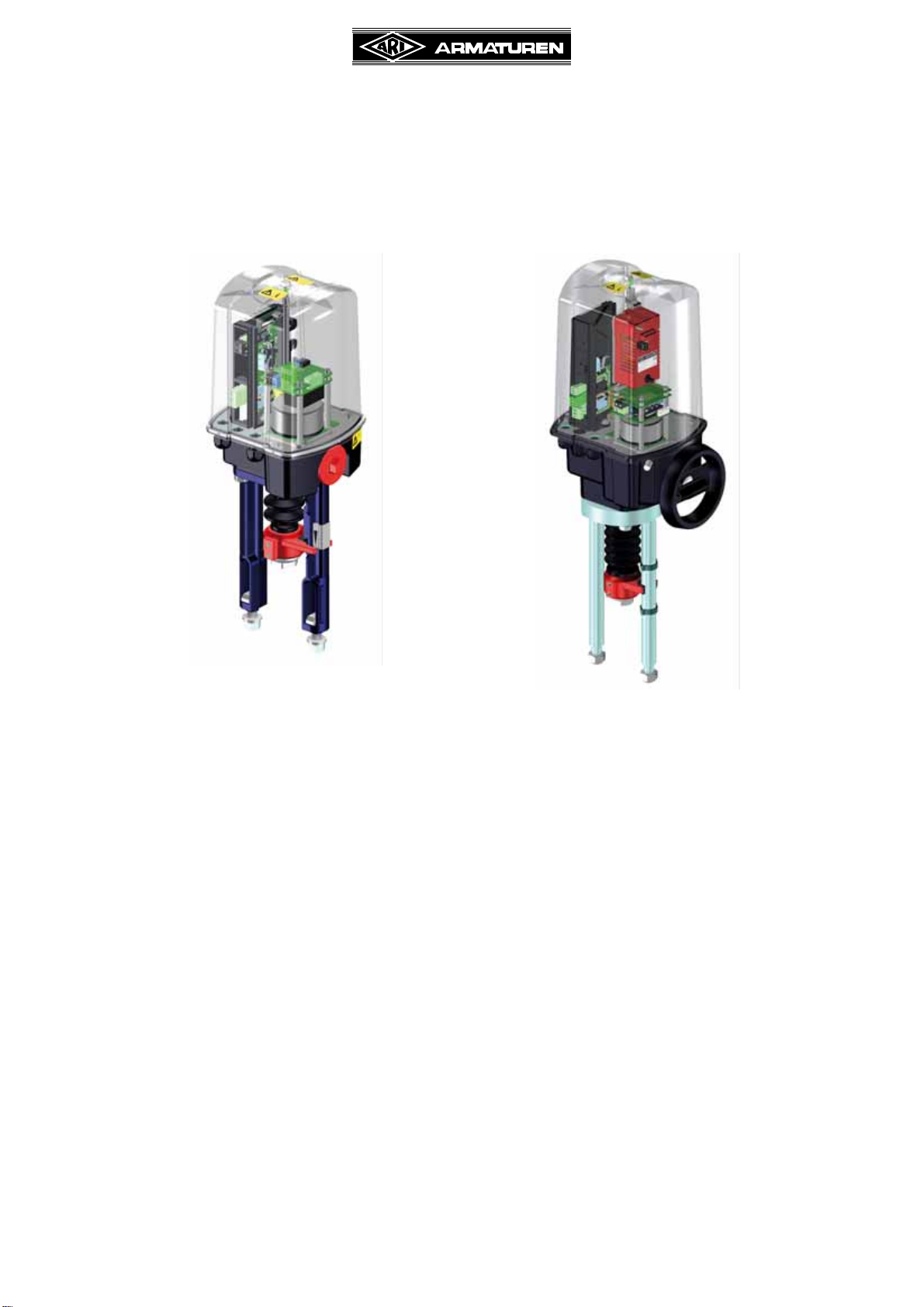
Electric thrust actuator ARI-PREMIO® 2,2 - 25kN
4.5 Accessories..............................................................................................................................................2-11
4.6 Dimensions ............................................................................................................................................. 2-13
5.0 Installation ..................................................................................................................................................... 2-14
5.1 General installation data ......................................................................................................................... 2-14
5.2 Manual operation .................................................................................................................................... 2-15
5.3 Mounting to valves .................................................................................................................................. 2-16
5.4 Electrical connection ............................................................................................................................... 2-17
5.4.1 Connection..................................................................................................................................... 2-17
5.4.2 Wiring diagram............................................................................................................................... 2-18
5.4.2.1 Standard ...........................................................................................................................................2-18
5.4.2.2 dTRON 316.......................................................................................................................................2-19
5.4.2.3 Accessories ......................................................................................................................................2-20
5.5 Installation and setting of options............................................................................................................ 2-21
5.5.1 Trip slide and setting S3 ............................................................................................................... 2-21
5.5.1.1 Installation.........................................................................................................................................2-22
5.5.1.2 Setting...............................................................................................................................................2-22
5.5.2 Additional travel switches and setting............................................................................................ 2-23
5.5.2.1 Method of functioning .......................................................................................................................2-24
5.5.2.2 Setting...............................................................................................................................................2-24
5.5.3 Potentiometers............................................................................................................................... 2-25
5.5.3.1 Method of functioning .......................................................................................................................2-25
5.5.3.2 Installation.........................................................................................................................................2-26
5.5.3.3 Setting...............................................................................................................................................2-26
5.5.4 Error-proof potentiometer for single-channel, error-proof position feedback ................................. 2-27
5.5.4.1 Method of functioning .......................................................................................................................2-28
5.5.4.2 Setting...............................................................................................................................................2-28
5.5.5 Heating .......................................................................................................................................... 2-29
5.5.5.1 Method of functioning .......................................................................................................................2-29
5.5.5.2 Installation.........................................................................................................................................2-29
5.5.6 Electronic position indicator RI21 / Electronic position controller ES11 ......................................... 2-30
5.5.6.1 Installation of one electronic ............................................................................................................2-30
5.5.6.2 Installation of two electronics............................................................................................................2-31
5.5.6.3 Electronic position indicator RI21 .....................................................................................................2-32
5.5.6.4 Electronic position controller ES11 ...................................................................................................2-32
5.5.7 Integrated processcontroller dTRON 316 ...................................................................................... 2-32
5.5.7.1 Method of functioning .......................................................................................................................2-32
5.5.7.2 Installation.........................................................................................................................................2-32
5.5.7.3 Setting...............................................................................................................................................2-33
6.0 Putting the actuator into operation .............................................................................................................. 2-34
7.0 Care and maintenance................................................................................................................................... 2-34
8.0 Troubleshooting............................................................................................................................................. 2-34
9.0 Troubleshooting table ................................................................................................................................... 2-35
10.0 Dismantlement of thrust actuator............................................................................................................... 2-36
11.0 Warranty / Guarantee................................................................................................................................... 2-37
12.0 Translated Declaration of Incorporation and Conformity ........................................................................ 2-38