manuals.online logo
Brands
  1. Home
  2. •
  3. Brands
  4. •
  5. Ariens
  6. •
  7. Lifting System
  8. •
  9. Ariens 79614000 User manual

Ariens 79614000 User manual

© Copyright 2009 • Ariens Company • Brillion, WI 54110-1072 03936900 6/09 Page 1 of 4
Instruction Sheet
Kit Number: 79614000
79614000 - ELECTRIC SNOW PLOW LIFT KIT
For use on Snow Plow Kits 796138 and 796139
For Gravely Models: 996120, 996140, 996141
For Treker Models: NT and ST
These instructions contain only information required to
assemble the kit to the unit. Read these instructions and
the Owner/Operator Manual thoroughly before beginning.
The Owner/Operator manual may include important
operation, adjustment, troubleshooting and maintenance
information for this and other accessories.
Parts and Owner/Operator Manuals can be downloaded
or ordered from www.gravely.com or by calling Ariens’
Technical Service at 888-927-4367. Model and serial
numbers are required to look up necessary manuals.
Parts List
Check the contents of your kit for the parts listed
(figure 1). Contact your local authorized Gravely Treker
dealer for any missing hardware.
WARNING: FAILURE TO FOLLOW
INSTRUCTIONS could result in personal
injury and/or damage to unit.
Read, understand, and follow all safety
practices in Owner/Operator Manual before
beginning.
CAUTION: Read, understand, and follow all
instructions and safety precautions before
beginning.
79614000 Kit
Item Part Number Qty. Description
1 EL100B 1 Gear Motor
2 EL120 1 Gear Pulley
3 EL121A 1 Motor Mount Plate
4 EL003 4 1-1/4 in. Spacer
5 EL122A 1 Bearing Plate
6 PUR1481 1 Lift Strap
7 CC18 1 1/8 in. Cable Clamp
8 U605 1 3/16" Quick Link
9 EL123 1 36" Cable
10 EL124 1 O-Ring
11 05967100 2 1/4-20 x 2.00 Hex Bolt
12 05948700 2 3/8-16 x 1.00 Hex Bolt
13 ELRELAY 1 Relay
14 WNRSHOUSING 1 Switch Housing
15 WNRSWITCH-3 1 R-3 Switch
16 CVC1316 1 13/16 in. Cable Clamp
17 SW10 1 #10 Star Washer
18 06442700 1 .219 x .50 x .049 Flat
Washer
19 06116900 1 10-24 x 3/4 Hex
Washer Head Machine
Screw
20 800-112C 6 Cable Tie .19 x 7.25
1.75D 50lb.
21 839-288C 1 20 Amp Fuse (5 Pack)
22 SCOTCHLOCK 1 ScotchlokTM Connector
23 EL136 1 O-Ring
24 EL119 1 Electrical Lift Pig Tail
25 STS10-212 2 #102-1/2"Self-Tapping
Screw
26 EL137 1 Wiring Harness
27 801-172C 1 Hex Screw
28 06535800 2 3/8-16 Locking Nylon
Nut
29 06531000 2 1/4-20 Locking Nylon
Nut
30 0653600 1 10-24 Nylon Locking
Nut With Insert
03936900 6/09 Page 2 of 4
Initial Preparations
Before installing the plow lift kit, be sure to secure
vehicle:
1. Park vehicle on a level surface. Do not work under
or around a vehicle parked on an incline.
2. Place shift selector in Park, turn ignition switch OFF
and remove key.
3. Chock front and back of a wheel to prevent vehicle
from rolling.
Installation
1. Fasten electric lift assembly to blade position lever
with two 3/8 x 1 in. hex bolts (item 12) and two hex
nuts (item 28).
2. Attach the lift strap (item 6) to the front of the unit
directly above the cable spool of the electric lift.
Mount so that the end of the strap is approximately
20 in. above the ground.
3. Attach the 3/16 in. quick link (item 8) to the end of
the strap (item 6). Do not attach the cable at this
time.
NOTE: Choose a location to mount the switch that will
not interfere with the normal function of the unit.
There are two options for mounting the switch (item 15):
• Mount the switch and switch housing (item 14) on
the front rack (if equipped).
• Mount the switch without the switch housing in the
unit’s dash.
To mount the switch and switch housing to the front rack:
a. Choose an accessible location and position the
13/16 in. cable clamp (item 6) on the front rack.
b. Secure the switch housing to the clamp with
one 10-24 x 3/4 hex head machine screw
(item 19), .50 flat washer (item 17) #10 star
washer (item 18) and 10-24 nylon locking nut
(item 30).
To mount the switch in the dash:
a. Remove the switch housing from the switch.
b. Locate an easily accessible area of dash to
mount the switch.
c. Mark a 7/8 x 1 1/2 in. vertical rectangle for the
switch cutout.
NOTE: A piece of masking tape cut to the hole
dimensions will provide a convenient template for
positioning, marking and cutting the hole.
d. Carefully cut the rectangular hole (figure 4).
Figure 1
1
3
8
15
23
4
5
6
7
24
16
9
25
17
26
18
10
21
19
11
27
2
22
14
13
12
20
30
28
29
Figure 2
Attach to inside
of hinge bracket.
CAUTION: Prevent damage! Ensure that no
components or wires are in the area of the cut.
Figure 3
86
03936900 6/09 Page 3 of 4
4. Route the red/white and black wires to the battery.
5. Attach the ring terminal on the black wire to the
negative (–) post of the battery.
6. Attach the ring terminal on the red/white wire to the
positive (+) post of the battery.
7. Route the red and brown leads of the wiring
harness (item 26) to the front of the unit and
connect to the lift motor plug. Attach the wiring
harness to the front of the unit with cable tie
(item 20).
IMPORTANT: Make sure that the front tie point of the
wiring harness to the unit allows full movement of the
plow without placing any tension on the harness.
8. Insert the relay (item 13) into the relay socket on
the wiring harness (item 26).
9. Using a 12-volt test light or meter, locate an existing
wire on the unit that is only energized when the key
switch is in the ON position.
10. Attach the yellow wire from the relay socket to the
wire just located with one Scotchlok connector
(item 22).
IMPORTANT: Connecting the yellow wire to a wire that is
not controlled by the key switch will discharge the battery.
11. Secure wiring harness to unit with remaining cable
ties.
12. Ensure that fuse is inserted in fuse holder and turn
the key switch to the ON position.
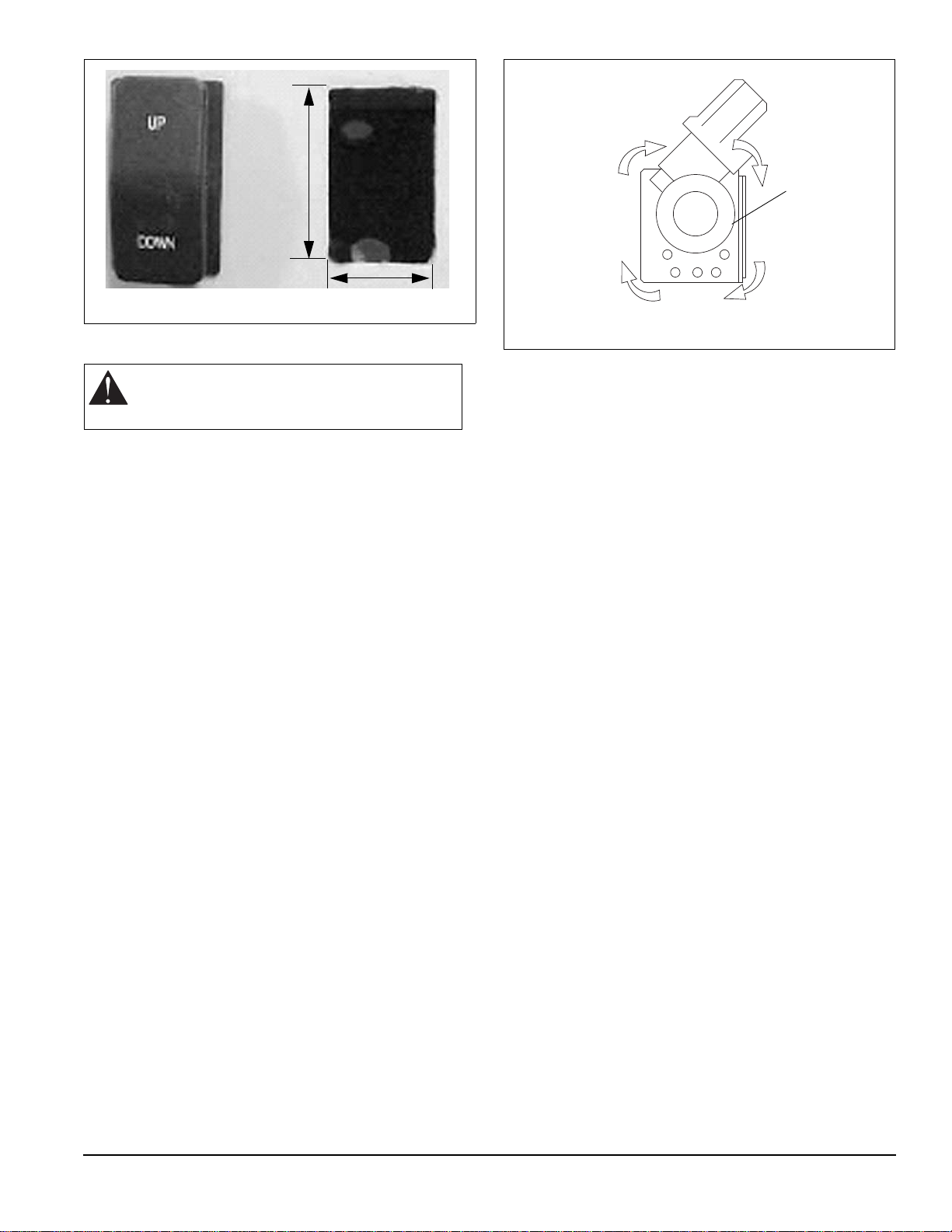
13. Press the motor switch to the UP position and verify
that the spool on the lift motor rotates clockwise
when viewed from the open end (figure 5). If the
spool rotates counter-clockwise refer to the wiring
diagram in figure 6.
14. Run the spool in the direction needed to result in
one wrap of cable on the spool and the cable to the
front of the spool.
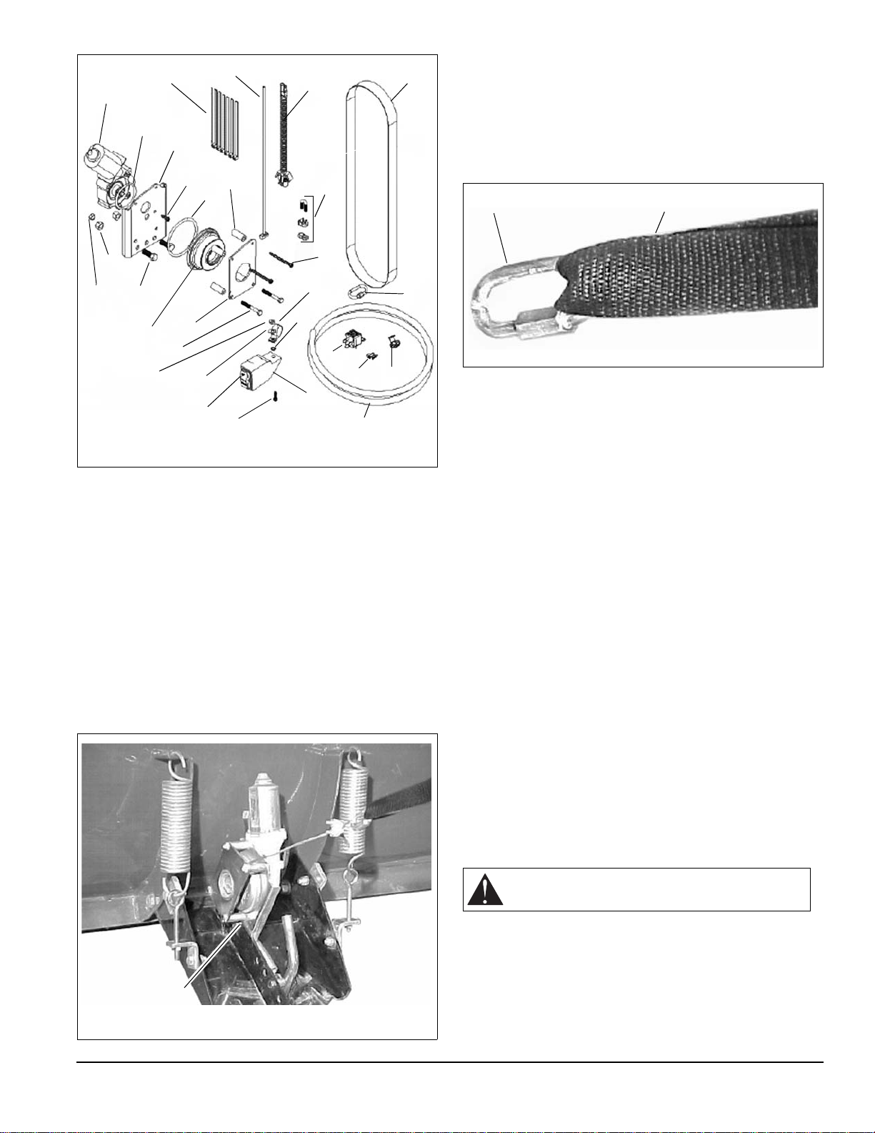
15. With the blade resting on the ground, route the end
of the cable up through the quick link (item 8) and
the lift strap (item 6) and secure it with the cable
clamp (item 7).
Operation
Press the blade switch in the UP position to raise the
blade and in the DOWN position to lower the blade.
Important operating points:
• Release the switch as soon as the blade is up. If the
blade is raised too high the push tube will contact
the unit’s frame and overload the gear motor and
other parts. This may also lead to fuse failure.
• Release the switch as soon as the blade is down. If
the switch is held in the DOWN position after the
blade is on the ground, the cable will start to wind
backward on the spool.
Occasionally lubricate each end of the spool with oil.
CAUTION: Ensure that all wires are routed
away from moving parts, hot components or
areas where they may be damaged.
Figure 4
1 1/2in.
7/8in.
Figure 5
Spool
03936900 6/09 Page 4 of 4
Figure 6

Popular Lifting System manuals by other brands

SignWarehouse PrismJET VJ-54 Guide Set Up

SignWarehouse

SignWarehouse PrismJET VJ-54 Guide Set Up

barbaric uniWood UWL 3 installation manual

barbaric

barbaric uniWood UWL 3 installation manual

RAM Trus-T-Lift Supplemental manual

RAM

RAM Trus-T-Lift Supplemental manual

Weaver W-1500 Installation & operation manual

Weaver

Weaver W-1500 Installation & operation manual

Smart Lift SL 608 user manual

Smart Lift

Smart Lift SL 608 user manual

Future Automation UBLS Application notes

Future Automation

Future Automation UBLS Application notes

SafeWaze SW900 manual

SafeWaze

SafeWaze SW900 manual

Prowise PW.1.21003 Series User documentation

Prowise

Prowise PW.1.21003 Series User documentation

Edco EH1500 Operator instructions

Edco

Edco EH1500 Operator instructions

Genie Z-45/25 Operator's manual

Genie

Genie Z-45/25 Operator's manual

Drive Medical Bellavita operating instructions

Drive Medical

Drive Medical Bellavita operating instructions

Braun Corporation UVL Series NUVL604XA Service manual

Braun Corporation

Braun Corporation UVL Series NUVL604XA Service manual

Neilsen CT1562 Original instructions

Neilsen

Neilsen CT1562 Original instructions

ReadyLift 69-21300 manual

ReadyLift

ReadyLift 69-21300 manual

Roemheld Shop-Floor operating instructions

Roemheld

Roemheld Shop-Floor operating instructions

Maxon GPT-25 Operation manual

Maxon

Maxon GPT-25 Operation manual

Genie TZ-34/20 Service manual

Genie

Genie TZ-34/20 Service manual

Genie Z-34/22 Operator's manual

Genie

Genie Z-34/22 Operator's manual

manuals.online logo
manuals.online logoBrands
  • About & Mission
  • Contact us
  • Privacy Policy
  • Terms and Conditions

Copyright 2025 Manuals.Online. All Rights Reserved.