Terberg OMNIDEKA User manual

A U TO M AT I C I N L I F T S Y S T E M
37878
Baronieweg 23, 3403 NL IJsselstein
The Netherlands
Telephone: (+31) 30 2100 600
Telefax: (+31) 30 2100 610
Homepage: www.terbergmachines.nl
E-mail: info@terbergmachines.nl
Translation of the original instruction
Issue date 05-2017
The original Dutch version (article code 37877) can be obtained
from Terberg. Please send a mail to: info@terbergmachines.nl
OMNIDEKA
OMNIDEKA
e

2EN
N
Contents
37878
05-2017
ãTerberg Machines .V., IJsselstein, The Netherlands
All rights reserved. No part of this book may be reproduced, stored in database or retrieval system, or published, in any form or in any way,
electronically, mechanically, by print, photoprint, microfilm or any other means without prior written permission from the publisher.
Page Page
FOR WORD
•General 3
•Warranty 3
•Operator requirements 3
•Symbols used 3
•Description of sections 3
•Type indication 3
1. INTRODUCTION
1.1 Description of the bin lift system 4
1.2 Technical specifications 5
in/container and bin lift information 5
2. SAF TY
2.1 General safety instructions 6
2.2 Safety instructions
2.2.1 During operation of the bin lift system 7
2.2.2 During maintenance and repair 7
2.3 Warning signs 8
2.4 Safety provisions: mergency stop button 9
Entrapment 9
2.5 Underwalk protection
(Rear Protection Device) 10
3. BIN LIFT OP RATION
3.1 Important components 12
3.2 Warnings and tips 13
3.3 Daily checks 13
3.4 Manual loading with the pick-up comb
3.4.1 2-Wheel bins 14
3.4.2 4-Wheel containers 15
3.5 Automatic loading with the pick-up comb
2-Wheel bins 16
3.6 Semi-automatic loading with the pick-up
comb
4-Wheel containers 17
3.7 Loading using SMT: Single Man Trade 18
3.8 Loading with DIN pick-up arms (optional) 19
3.9 Shake function 2-wheel bins (Green waste) 20
3.10 Transport and travel positions 20
3.11 Diagnostic System 22
3.11.1 Level 1: Home screen / messages 23
3.11.2 Level 2: Monitor 24
3.11.3 Level 3: in counter (optional) 25
3.11.4 Level 4: Configuration menu 25
3.11.5 Level 5: Settings 27
4. MAINT NANC AND CL ANING
4.1 General and daily maintenance 32
4.2 Weekly maintenance 33
4.3 Six-weekly maintenance 34
4.4 Annual maintenance 35
4.5 Maintenance schedule 37
4.6 Trouble shooting 39
Alarm messages 40
5. TRANSPORT AND STORAG 53
6. INSTALLATION AND COMMISSIONING
6.1 Dimensions of the bin lift 54
6.2 Minimum free space required in
compactor body 55
6.3 Mounting the bin lift on the RCV 56
6.3.1 Height of side guards / safety arms 57
6.3.2 Entering the mounting height (Diagn. Syst.) 59
6.3.3 Calibrating position sensors (Diagn. Syst.) 60
6.4 Hydraulic connection to compactor body 61
6.5 lectrical connection to compactor body 62
7. D COMMISSIONING (disposal) 65
8. APP NDIC S
8.1 Hydraulic connections and components 66
8.1.1 Hydraulic block, overview components 68
8.1.2 Valves for lifting and tipping cylinders &
catcherbar 69
8.2 lectrical connections and components 71
8.2.1 Overview Inputs 80
8.2.2 Overview Outputs 81
8.3 Special tools 82
Additional information
for the L CTRIC V RSION 83
SPAR PARTS BOOK 101

EN 3
N
37878
05-2017
Foreword
ãTerberg Machines .V., IJsselstein, The Netherlands
All rights reserved. No part of this book may be reproduced, stored in database or retrieval system, or published, in any form or in any way,
electronically, mechanically, by print, photoprint, microfilm or any other means without prior written permission from the publisher.
Foreword
This user manual provides information about the
operation and maintenance of the OmniD KA
automatic bin lift system.
In order to work safely and efficiently with this
automatic bin lift system, it is essential that you read
this manual carefully before putting the bin lift into
use.
The operation and appearance of components and
button control stations may differ, this depends on
the version ordered.
Make the user manual available to everyone concer-
ned with the operation and/or the maintenance of
the bin lift.
Where necessary, refer to the user manual of the
refuse collection vehicle and the refuse handling
body.
When all the operating and maintenance instructions
have been met the bin lift can be safely used.
Should you nonetheless have any further questions,
please get in touch with your distributor.
Warranty
For more information about the conditions of
warranty, please contact your distributor.
Operator requirements
- The bin lift system may only be operated by
persons who are familiar with the operation of the
bin lift.
- Repairs may only be carried out by qualified
personnel.
Symbols used
NOT :
Additional information.
CAUTION:
If these instructions are not followed, this
may result in slight to average injury and/or
damage to the product or the environment.
WARNING:
If these instructions are not followed, this
may result in serious or fatal injury and/or
serious damage to the product or the
environment.
The user manual has the following sections:
1. Introduction
A description of the function, conditions of use and
the operating principle of the machine.
2. Safety
Description of the safety provisions and the mea-
sures that need to be taken into account in order to
work safely with the machine. As well as an explana-
tion of the symbols on the machine.
3. Operating
A clear description of the most important compo-
nents, instructions for emptying various types of bins
and information about the Diagnostic System.
4. Maintenance and cleaning
Covers all the periodic operations needed for the
correct functioning of the machine, trouble shooting
and fault diagnosis.
5. Transport and storage
Information about the weight, the centre of gravity
and how to store the machine.
6. Installation and commissioning
A description of the installation dimensions for the
machine when being built onto the RCV (Refuse
Collection Vehicle), including a list of means and
tooling required to conduct the installation.
7. Decommissioning
Description of the actions necessary to dismantle the
machine safely and to dispose of this in an environ-
mentally-friendly manner.
Type indication
Each bin lift is provided with a type plate with the
type indication, machine number and year of con-
struction. The type plate can be found on the right-
hand side of the frame.

13
14
15
16
17
03
01
04
20
17
07
11
08
09
06
18
09
05
08
06
19
12
05
17
07
11
20
04
02
17
10
10
18
21
21
optional 02
01. Button control station R/H* with integrated emergency stop
02. Button control station L/H* with integrated emergency stop
03. Diagnostic System*
04. Safety arm
05. Lifting chair
06. Pick-up comb
07. Locking plate
08. Bin security switch
09. Pedal arm (cycle start switch)
10. Position for RFID antenna
11. Bin guide plate
12. 4-Wheel container detection
13. Catcherbar
14. Catcherbar 1100 litre containers
15. Guide track - lid opener
16. Dust curtain (tarpaulin)
17. Protective screen/window
18. DIN pick-up arms (optional)
19. Chair lock, mechanical (optional)
20. Taillights (optional)
21. Handle bar (optional)
4EN
N
1. Introduction
37878
05-2017
1.1
Description of the bin lift system
ãTerberg Machines .V., IJsselstein, The Netherlands
All rights reserved. No part of this book may be reproduced, stored in database or retrieval system, or published, in any form or in any way,
electronically, mechanically, by print, photoprint, microfilm or any other means without prior written permission from the publisher.
01 optional
* Country dependent: - The position of the control stations have been switched.
- The Diagnostic System is mounted on the left or right hand side of the bin lift.
14
For lower 4-wheel containers (deviating
from the standard) the catcherbar (14)
may be replaced by 2 of these stops
left and right (optional).

The OmniD KA is a versatile automatic bin lift system. This bin lift system is suitable for emptying the normal
2-wheel bins as well as for emptying most 4-wheel containers (see table 1.2b). With the (optional) pick-up arms,
4-wheel containers that are not fitted with a comb pick-up edge can be emptied.
A safe advantage of this bin lift is that the bin moves away from the operator during the lifting motion.
Operation is done using the two button control stations on each side of the bin lift.
If the bin lift is fitted with an automatic function, then this function can be activated on the button control
station. The bins then only need to be wheeled up against the pick-up comb. The bins/containers are picked up
automatically, clamped, tipped over and put down again.
The bin lift can optionally be provided with a semi-automatic function for 4-wheel containers. This function has
a slightly different mode of operation, you will find more about this in the chapter 'Operation'.
The automatic and semi-automatic functions only work with the safety arms in the horizontal position.
The bin lift is fitted with a passive catcherbar, no adjustment per bin/container type is needed.
EN 5
N
37878
05-2017
1. Introduction
1.2
Technical specifications
ãTerberg Machines .V., IJsselstein, The Netherlands
All rights reserved. No part of this book may be reproduced, stored in database or retrieval system, or published, in any form or in any way,
electronically, mechanically, by print, photoprint, microfilm or any other means without prior written permission from the publisher.
1.1
Description of the bin lift system
Guidelines and standards 2006/42/EG, EN 1501-1 & EN 1501-5:2011
Weight 650 kg standard (685 kg with DIN pick-up arms)
Noise level without bin/container ≤ 61 d (A)
Noise level (according N1501-4 6.4.3) ≤ 70 d (A)
Vibrations ≤ 2.5 m/s2
Operating voltage 24 Volt DC
Maximum current consumed by controls 7.5 Ampère / 24V DC
Required oil flow 40 litres/minute
Required working pressure Min. 200 bar
Return pressure Max. 2.0 bar at 70 litres/minute
Quick release couplings DIN 25, ISO 72141-1
Table 1.2a Technical data OmniD KA
Table 1.2b Bins/containers to be emptied
The emptying of bin/container types other than those
indicated above, is not permitted with this bin lift sys-
tem. If in doubt, please contact your distributor.
2-wheel bins
4-wheel containers
with flat lid
4-wheel containers
with roll top
Paladin
containers
Capacity 80 - 360 litres 500 - 1280 litres 770 and 1100 litres 900 litres
According to standard EN 840-1 EN 840-2 EN 840-3 --
Lifting capacity (maximum) 1700N (170 kg) 5000N (500 kg)
Cycle time* (excl. dwell time) 5-7 seconds 10-12 seconds
Time in tipping position Adjustable
* Depending on mounting height, bin/container weight and oil temperature.
The bin lift is an 'interchangeable lifting device' in compliance with EN 1501-5:2011.
For information: This bin lift system has been designed for mounting onto refuse collection vehicles that are fitted
with a standard interface (mechanical, hydraulic, electrical, for technical dimensions and functionality).

•The bin lift may not be operated under any
circumstances if the oil flow is greater than
60 litres/minute.
•Technical faults must be reported immediately to
the person who is responsible for the supervision
of the bin lift. The bin lift must be put out of action
until the fault (that could cause danger) has been
repaired.
•Never use the lifting chair, pick-up arms or other
parts of the bin lift system as a seat,
this is life
threatening!
•Under no circumstances may the controls be
changed.
•Under no circumstances may any of the safety
provisions fitted be removed or changed.
•Don’t blind off or cover the ultrasonic sensors, fit-
ted in the safety arms, under any circumstances.
•If the safety provisions are damaged they must be
repaired or replaced immediately by original parts.
•Under no circumstances may the cycle speeds and
lifting forces set by the manufacturer be changed.
•Operating and safety decals must be present and
properly legible.
•Actions that override the safety provisions are
expressly forbidden!
•The lifting chairs should be positioned in their tra-
vel position before reversing.
•It is not permitted to stand on the footboards
while the refuse collection vehicle is reversing.
•Make sure that you are visible to the driver of the
refuse collection vehicle when it is reversing.
•The bin lift may never be used as a hoisting
instrument.
•No vehicle may be towed with the towing cable
attached to the bin lift system.
•The refuse collection vehicle may never be lifted
by the lifting points of the bin lift.
•The pick-up arms should be folded in while the
vehicle is in motion.
•When riding on the vehicle you must absolutely
not sit or stand on parts of the machine other
than the special footboards for this purpose,
this
really is extremely dangerous!
•In extremely bad weather (storms, thunder-
storms, etc.) it is not advisable to use the bin lift
system.
6EN
N
2. Safety
37878
05-2017
2.1
General safety instructions
ãTerberg Machines .V., IJsselstein, The Netherlands
All rights reserved. No part of this book may be reproduced, stored in database or retrieval system, or published, in any form or in any way,
electronically, mechanically, by print, photoprint, microfilm or any other means without prior written permission from the publisher.
Terms of conformity
This bin lift conforms to the current standards at the
time of production. It has been tested and checked,
on a rig, in normal conditions with an increase of
25% weight in static and 10% weight in dynamic
operation.
It is the end user’s responsibility to maintain the
equipment in accordance with the manufacturer’s
recommendations, also if there is a risk of damages
or injury the bin lift must be taken out of service
immediately.
General
•The bin lift system may never be operated when
the refuse collection vehicle is travelling along and
also not with reverse gear engaged.
•The bin lift may only be operated by persons who
have received operator training and are fully
familiar with the working of the bin lift.
•Read the operating instructions carefully before
taking the bin lift into service.
•Also read the instructions for the compactor
carefully.
•You will be working where traffic is present during
your daily work as operator of the bin lift. Do not
endanger yourself or other road users during your
daily operations with the bin lift.
•efore commencing the run discuss and agree
with your colleagues how to act in particular
situations such as stopping, driving away, etc.
•When you are working with the bin lift system you
may not wear any loose hanging clothing or
jewellery.
•Always wear work clothing, safety shoes and work
gloves that comply with the standards shown in
the table below while working with the bin lift.
•Make sure that an unattended bin lift can never be
started by a person who is not authorised to do
so (remove ignition key whenever the vehicle is
left unattended).
•Don’t use the bin lift in areas or near installations
where there is a risk of fire and/or explosion due
to the presence of gases and/or combustible
substances.
Personal protection
equipment: According to standard:
Work clothing NEN-EN-ISO 20471:2013
Safety shoes NEN-EN-ISO 20345:2011
Work gloves NEN-EN 420:2003+A1:2009

EN 7
N
37878
05-2017
2. Safety
2.2
Safety instructions applicable during operation, maintenance and repair
ãTerberg Machines .V., IJsselstein, The Netherlands
All rights reserved. No part of this book may be reproduced, stored in database or retrieval system, or published, in any form or in any way,
electronically, mechanically, by print, photoprint, microfilm or any other means without prior written permission from the publisher.
2.2.1 During operation of the bin lift system
•This bin lift has not been designed for throwing in
loose refuse. Should you decide to load loose
refuse, bags or boxes, then ALWAYS SWITCH the
AUTOMATIC function OFF. Always also do this
when removing refuse from the lifting chairs.
•Don’t go between the safety arms if the automatic
function is activated.
•Always switch the automatic function off if for any
reason you need to enter between the safety
arms.
•Make sure that there are no persons in the imme-
diate vicinity of the bin lift during the loading cycle.
•When the bin lift system is operating, under no
circumstances is it permitted to put your hand in
the bin lift system (Risk of injury).
•In the event of danger immediately press the
nearest emergency stop switch
(see chapter Safety provisions 2.4).
•Check that there are no foreign objects in or
between the bin lift system that could obstruct its
working.
•Compacting may not be carried out when there
are objects sticking out of the throw-in opening.
•Don’t use the bin lift system in situations where
there is poor visibility of the bin lift.
•Never use the bin lift system on a very uneven
surface.
•The bin lift system may not be driven up against a
bin/container or a pile of refuse.
•Take account of the heating of the hydraulic oil.
This can become 40°C warmer than the environ-
ment. As a result, the pipes and hoses can cause
light burns at high ambient temperatures.
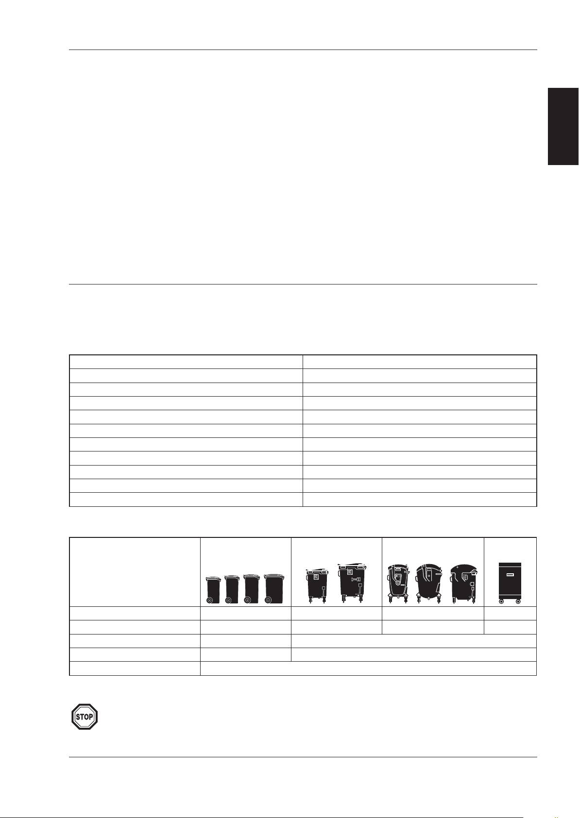
•It is not permitted to work with bin/container
types other than those stated in the manual.
•Nothing should protrude from the bin and only
bins whose lids are fully closed should be emptied.
•Don’t empty damaged bins/containers. These can
cause problems.
•Overweight bins/containers should be removed
from the bin lift system:
max. lifting capacity 2-wheel bins: 1700N (170kg)
max. lifting capacity 4-wheel cont.: 5000N (500kg)
•Check that the bin/container is positioned cor-
rectly on the pick-up comb before emptying it.
•Let go of the bin/container as soon as it is lifted.
•It is expressly forbidden to ‘manually’ assist the
lifting cycle by hand.
•Only apply extra shaking if there is a need for this.
•Only take the bin/container away when the bin lift
has come to a standstill and the bin/container is
back on the ground.
•Place empty bins/containers where they will not
cause a danger to other road users.
•It is forbidden to empty bins/containers containing
hazardous and/or radioactive substances.
•It is forbidden to empty bins/containers containing
smouldering or burning substances.
•Never walk backwards in the direction of the bin
lift system.
•Two bin presenting and/or taking at a time by one
person should be kept to a minimum.
•A bin may only be offered to the bin lift system
when held by the handle bars.
•Always push a 2-wheel bin to the bin lift with two
outstretched arms.
•Never bend your body over the bin when offering
it to the bin lift.
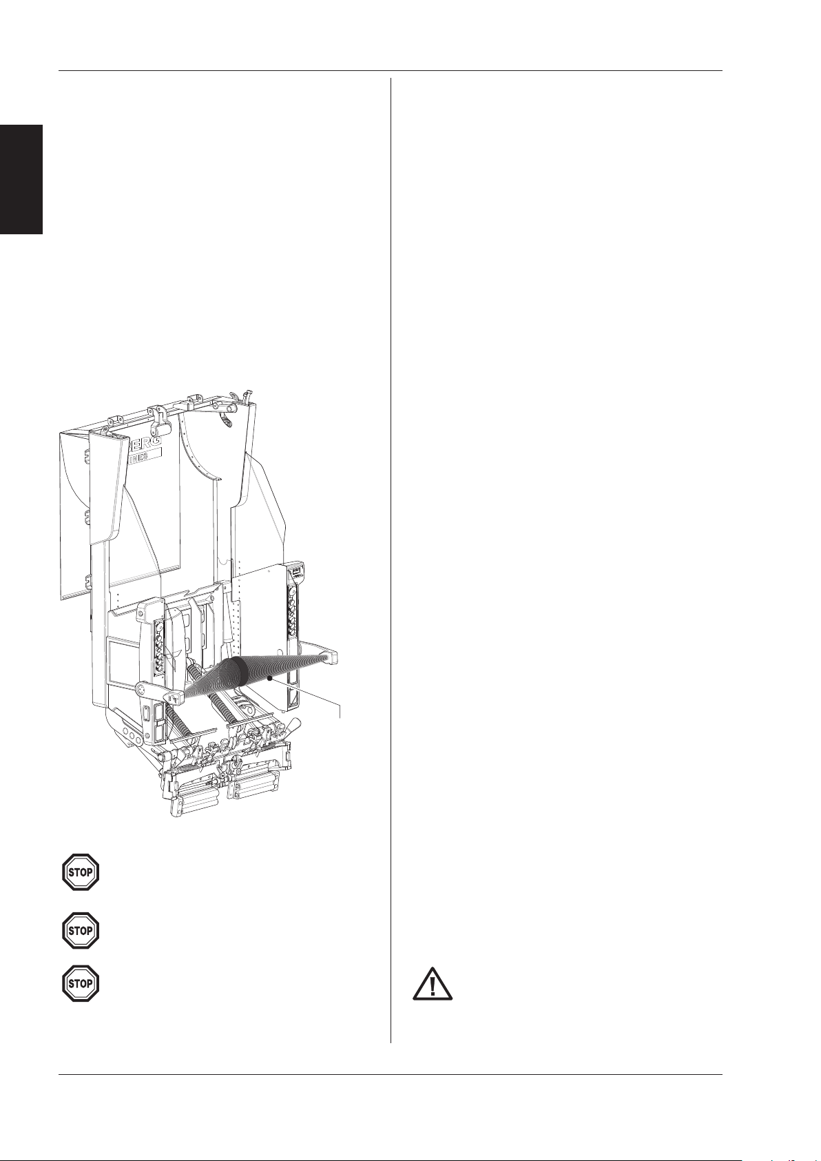
•Under wintry conditions, if the bin lift is blocked
with large amounts of ice or snow deposits, the
sensors may become concealed or the bin clam-
ping mechanism may become clogged up.
Apply emergency stop switch prior to cleaning.
Clean these parts and keep as dry as possible, for
example with a broom. Never clean the bin lift
using defrosting liquids!
2.2.2 During maintenance and repair
•Maintenance and carrying out of repairs is only
permitted for qualified technical personnel.
•Any faults detected should be corrected before
the bin lift system is used.
•During maintenance and repair work switch off
the bin lift system (switch off the engine of the
refuse collection vehicle and the main power
switch).
•During repair work it must be made impossible
for unintentional switching on to occur, therefore
remove the ignition key from the ignition switch
(keep on your person).
Keep a minimum distance of 2.5 meter
between the bin lift and objects which are
located behind the bin lift system. This is to
avoid a dangerous situation in case that a
bin/container falls from the pick-up comb.

Warning signs
All safety and instruction decals must be replaced
when damaged.
The pictogram decals have the following meaning:
8EN
N
2. Safety
37878
05-2017
2.2
Safety instructions
(continued)
ãTerberg Machines .V., IJsselstein, The Netherlands
All rights reserved. No part of this book may be reproduced, stored in database or retrieval system, or published, in any form or in any way,
electronically, mechanically, by print, photoprint, microfilm or any other means without prior written permission from the publisher.
•You may not go under the lifting chairs for repair
or cleaning unless the lifting chairs are adequately
supported.
•Switch off the drive of the refuse collection
vehicle before beginning cleaning.
•It is possible that grease can squirt out from the
hinge points when a high pressure cleaner is used,
protect your eyes by always wearing safety glasses.
•Use the lifting points provided to raise the bin lift.
•When working on the hydraulic system, you
should bear in mind that this is filled with hydraulic
fluid under pressure. Always use personal protec-
tion equipment to avoid contact with skin and
eyes. Use collecting trays / absorbents to avoid
environmental pollution.
•You must comply with the maintenance interval
prescribed by the manufacturer.
•Electrical fuses should never be bridged or
replaced by a fuse with a higher capacity.
•When dismantling, disconnect the plugs and
couplings from the vehicle.
•Following a collision involving the bin lift system
Terberg will need to assess whether it is still safe
to use or first needs to be repaired.
•Original or specified parts should always be used
for repair or maintenance.
•Do not stand under the bin lift or the
bin/container!
Repairs may only be carried out by qualified
personnel, never rectify faults yourself, this
may cause danger for you and damage to the
bin lift system!
2.3
Warning signs
00000
The above decal has been affixed to the inside left and
right of the bin lift.
This decal has been affixed to the outside left and right
of the bin lift.
Onderdeelnummer: 37866
Omschrijving: Sticker UK OmniDEKA (tbv Engelse markt)
Afmeting: 360x310 mm
Afronding: R=5
Materiaal: ZelfklevendHighTack
Wit hoogglanzend
Bedrukking: Licht grijs 427 C 100%
Donker grijs Cool gray 10 C 100%
Blauw 072 C 100%
Rood 485 C 100% of Warm Red 100%
Zwart 100%
0
1
Rev. Wijziging Datum
Nieuw
Company richtlijn aanpassing:
- logo Terberg RosRoca*,
- OMNIDEKA in Ubuntu font
11-07-2016
01-12-2016
*Let op de witte vlakken in de Terberg ‘T’.
37866
Paladin
Necessary setting / Choice between 2-wheel
bins and 4-wheel containers.
Information and safety:
- CE certification mark.
- Read the user manual!
- Various constructions have been patented.
- Communications network refuse collection vehicles.
- Lubrication interval + grease recommendation!
- Do not stand under the lifting chair!
- Maximum capacity 2-wheel bins!
- Maximum capacity 4-wheel containers!

•Press the dark blue DOWN
button. The lifting chair
lowers to the lowest posi-
tion.
•Solve the reason for pressing
the emergency stop button.
•Remove the bin/container
from the bin lift system if
applicable.
•
The bin lift system is ready for use again.
ntrapment
In the event of a dangerous occurance or if a person
has become trapped in the lifting mechanism and
consequently the emergency stop button has been
pressed.
The system will need to be reset to allow the lif-
ting chair to be raised or lowered which ever is
appropriate to release the person.
An understanding of the resetting procedure of the
compactor body will be required of the operators.
In such cases, proceed as follows:
•Reset the emergency stop
button by pulling it out. The
buzzer in the cabin stops.
•Press the dark blue DOWN
button to allow the lifting
chair to lower or the light
blue UP button to allow the
lifting chair to raise.
EN 9
N
37878
05-2017
2. Safety
2.4
Safety provisions: mergency stop button
ãTerberg Machines .V., IJsselstein, The Netherlands
All rights reserved. No part of this book may be reproduced, stored in database or retrieval system, or published, in any form or in any way,
electronically, mechanically, by print, photoprint, microfilm or any other means without prior written permission from the publisher.
General
•If it is noticed that the bin lift system does not
work or has a fault while collecting refuse, the
workshop or service station must be informed
immediately with a clear description of the defect.
mergency stop button
In case of emergency, you can use the emergency
stop buttons (positioned in the button control
stations on both sides of the bin lift) to immediately
stop the compactor and the loading cycle of the bin
lift.
Emergency stop
button identifier.
•After the red emergency
stop button is pressed, the
supply of hydraulic oil stops
and the electrical circuit is
interrupted.
•The check lights for auto-
matic working go out. The
driver of the refuse collec-
tion vehicle is warned by a
buzzer in the cabin that the
emergency stop button has
been pressed.
Reset emergency stop button
•Reset the emergency stop
button by pulling it out. The
buzzer in the cabin stops.
•Resetting of the compactor
body may be required, con-
sult the body manual for
the correct procedure.
Repairs may only be carried out by qualified
personnel, never rectify faults yourself, this
may cause danger for you and damage to the
bin lift system!

10 EN
N
2. Safety
37878
05-2017
2.5
Underwalk protection (R
ear
P
rotection
D
evice
)
ãTerberg Machines .V., IJsselstein, The Netherlands
All rights reserved. No part of this book may be reproduced, stored in database or retrieval system, or published, in any form or in any way,
electronically, mechanically, by print, photoprint, microfilm or any other means without prior written permission from the publisher.
To comply with European Standard EN 1501-5, all
automatic and semi-automatic bin lift systems are
equipped with an underwalk protection (RPD).
This safety provision protects persons approaching
the bin lift when it is emptying automatically (or semi-
automatically).
This safety provision consists of two ultrasonic sen-
sors fitted in both safety arms. The sensors detect
persons or objects coming within the protected area
of the bin lift. This occurs separately for each lifting
chair.
The underwalk protection (RPD) is therefore only
active when lifting automatically (or semi-automa-
tically) and with the safety arms in horizontal
position.
•As soon as the area under a lifted bin is entered,
during automatic or semi-automatic lifting, the
downward movement is stopped.
- The green 'automatic' light in the button
control station flashes rapidly when the RPD on
that side of the bin lift is activated.
- However, the automatic (or semi-automatic)
loading setting will remain activated.
•Lower the chair manually using the manual push-
buttons, the warning light goes out and the RPD is
reset.
- The bin lift is again ready to lift bins automatically
(or semi-automatically), the green light shows a
steady light again.
The sensors are checked during each automatic
lifting operation. When a sensor fault is identified the
automatic lifting is switched off.
•The RPD system is designed such that it is not
activated by rain or snow. When refuse, snow or
another object block the ‘unobstructed view’ of a
sensor, the lifting chair will rise and then stop.
- The green 'automatic' light will go out.
- The Diagnostic System display will show the
message 'AR A PROT CTION S NSOR
FAULT'.
This indicates that the 'unobstructed view' of
the sensor is being blocked, or that there is a
defect in the RPD system.
- The bin lift will still work in manual mode, even
with an RPD error.
ecause the RPD sensors monitor both sides of the
bin lift separately, in case of a defect on one side the
other will still lift automatically.
Semi-automatic function 4-wheel containers
(optional)
When the bin lift is equipped with the semi-automatic
function 4-wheel containers, the activation of the
RPD on one of the two sides will result in the bin lift
stopping in the tipping position.
In case of damage to the safety equipment,
this must be repaired or replaced by original
parts immediately.
Repairs to the RPD may only be carried out by
qualified personnel.
Keep a minimum distance of 2.5 meter
between the bin lift and objects which are
located behind the bin lift system. This is to
avoid a dangerous situation in case that a
bin/container falls from the pick-up comb.
Do not use defrosting fluids for accumulated
snow or ice removal, this leaves a sticky layer
and snow accumulates even faster.
Follow the safety procedure and sweep
accumulated snow BY HAND!
Protected
area

EN 11
N
37878
05-2017
ãTerberg Machines .V., IJsselstein, The Netherlands
All rights reserved. No part of this book may be reproduced, stored in database or retrieval system, or published, in any form or in any way,
electronically, mechanically, by print, photoprint, microfilm or any other means without prior written permission from the publisher.
THIS PAG INT NTIONALLY L FT BLANK

12 EN
N
3. Bin lift operation
37878
05-2017
ãTerberg Machines .V., IJsselstein, The Netherlands
All rights reserved. No part of this book may be reproduced, stored in database or retrieval system, or published, in any form or in any way,
electronically, mechanically, by print, photoprint, microfilm or any other means without prior written permission from the publisher.
3.1
Important components
13
14
15
16
17
03
01
04
20
17
07
11
08
09
06
18
09
05
08
06
19
12
05
17
07
11
20
04
02
17
10
10
18
21
21
optional 02
01. Button control station R/H* with integrated emergency stop
02. Button control station L/H* with integrated emergency stop
03. Diagnostic System*
04. Safety arm
05. Lifting chair
06. Pick-up comb
07. Locking plate
08. Bin security switch
09. Pedal arm (cycle start switch)
10. Position for RFID antenna
01 optional
* Country dependent: - The position of the control stations have been switched.
- The Diagnostic System is mounted on the left or right hand side of the bin lift.
11. Bin guide plate
12. 4-Wheel container detection
13. Catcherbar
14. Catcherbar 1100 litre containers
15. Guide track - lid opener
16. Dust curtain (tarpaulin)
17. Protective screen/window
18. DIN pick-up arms (optional)
19. Chair lock, mechanical (optional)
20. Taillights (optional)
21. Handle bar (optional)

EN 13
N
37878
05-2017
3. Bin lift operation
3.2
Warnings and tips
3.3
Daily checks
ãTerberg Machines .V., IJsselstein, The Netherlands
All rights reserved. No part of this book may be reproduced, stored in database or retrieval system, or published, in any form or in any way,
electronically, mechanically, by print, photoprint, microfilm or any other means without prior written permission from the publisher.
•It is expressly forbidden to ‘manually’ assist the
lifting cycle by hand.
•Lifting capacity 2-wheel bins: max. 170 kg.
Lifting capacity 4-wheel containers: max. 500 kg.
•Overweight bins/containers should be removed
from the bin lift system.
•Do not remove the bin/container before the bin
lift has come to a standstill.
•Always approach the bin lift forwards with out-
stretched arms, even when removing the bin/con-
tainer.
•You will be working where traffic is present, do
not endanger yourself or other road users. Place
empty bins/containers where they do not cause
any danger to other road users.
•When you are working with the bin lift system you
may not wear any loose hanging clothing or
jewellery.
•Loading is teamwork. efore commencing the run
discuss and agree with your colleagues how to act
in particular situations such as stopping, driving
away, etc.
•Never use the bin lift system as a seat.
This is life-
threateningly dangerous.
•When the bin lift system is in operation, you may
not reach into the lifting system, this may cause a
danger of injury.
•It is forbidden to stand on the footboards while
the refuse collection vehicle is reversing.
•Make sure that you are visible to the driver of the
refuse collection vehicle when it is reversing.
Before you start work, you must check the bin lift
system for the following points:
•Check that no oil loss has occurred.
•Look to see if there are any foreign objects
(branches, twigs, plastic bags, etc) in the bin lift sys-
tem that could hinder its operation.
•Operation of the controls
Check the operation of all the controls by per-
forming all the possible actions with empty
bins/containers:
- Emergency stop buttons
- Catcherbar
- Shaking
- Manual operation
- Automatic function
- Start sensors and 4-wheel recognition.
•Working footboards (optional)
Check the operation and mounting of the foot-
boards.
Before starting to use the bin lift system, first
read the operating instructions.
A= mergency stop button
B= Check light AUTOMATIC mode (green)
C= Push button AUTOMATIC mode (light green)
D= Push button TRAV L H IGHT (black)
= Selector switch 2-wheel / 4-wheel
F= Push button S MI-AUTOMATIC mode (dark green), option
G= Push button UP (light blue)
H= Push button DOWN (dark blue)
J= Selector switch SHAKING
Optional Button control stations
K= Push button 2-wheel / 4-wheel (black)
A
B
C
D
F
G
H
K
J
J
A
B
C
D
F
G
H
K
Optional Optional

5) Remove the bin:
-Press the dark blue
DOWN button (H).
The bin lowers to the
ground.
-Pull the bin out of the bin
lift as soon as the wheels
touch the ground.
14 EN
N
3. Bin lift operation
37878
05-2017
ãTerberg Machines .V., IJsselstein, The Netherlands
All rights reserved. No part of this book may be reproduced, stored in database or retrieval system, or published, in any form or in any way,
electronically, mechanically, by print, photoprint, microfilm or any other means without prior written permission from the publisher.
1) Switch on the refuse collection vehicle's
compactor body.
2) Select 2-wheel bins:
Set the rotary switch (E) to
2-wheel bins.
[Or press the black button (K), this
can be done on both button
control stations.
The left-hand ED next to the
2-wheel bin should light up.] *
3) Roll the bin against and over the pick-up comb
(06).
4) mpty the bin:
Press the light blue UP but-
ton (G), on the side of the
lifting chair selected.
The bin will be lifted to the tip-
ping position and emptied.
If any refuse remains stuck in the bin, you can give it
an extra shake by keeping the UP button pressed.
3.4.1 2-wheel bins;
capacity 80 to 360 litres
according to N 840-1
Chamberlain Chamberlain
For manual loading, the safety arms (04) do
not need to be folded down.
Because in manual operation the bin security
switch is deactivated, great care must be
taken that the bin is located correctly on the
pick-up comb.
The optional DIN pick-up arms (18) must be
folded in.
3.4
Manual loading with the pick-up comb
[ ] * This text applies to the optional button control stations. See 'Important components' at the start of this chapter.
Only give an extra shake if there is a need for
this. Shaking takes time and causes extra
noise for the surrounding area.

EN 15
N
37878
05-2017
3. Bin lift operation
3.4
Manual loading with the pick-up comb
(continued)
ãTerberg Machines .V., IJsselstein, The Netherlands
All rights reserved. No part of this book may be reproduced, stored in database or retrieval system, or published, in any form or in any way,
electronically, mechanically, by print, photoprint, microfilm or any other means without prior written permission from the publisher.
3.4.2 4-wheel containers;
with ROLL top;
capacity 770-1100 litres
with FLAT lid;
capacity 500 to 1280 litres
1) Switch on the refuse collection vehicle's
compactor body.
2) Select 4-wheel containers:
Set the rotary switch (E) to
4-wheel containers.
[Or press the black button (K), this
can be done on both button
control stations.
The right-hand ED next to the
4-wheel container should light up.] *
Both the lifting chairs will go to
the correct height for loading
4-wheel containers.
3) Roll the container against and over the pick-up
combs (06).
4) mpty the bin:
Press the light blue UP but-
ton (G), on one of the two
button control stations.
The container will be lifted to
the tipping position and emp-
tied.
Because in manual operation the container
security switch is deactivated, great care must
be taken that the container is located correctly
on the pick-up combs.
If any refuse remains stuck in the container, you can
give it an extra shake by keeping the UP button
pressed.
5) Remove the bin:
-Press the dark blue
DOWN button (H).
The container lowers to the
ground.
-Pull the container out of
the bin lift as soon as the
wheels touch the ground.
[ ] * This text applies to the optional button control stations. See 'Important components' at the start of this chapter.
The bin lift may be optionally fitted with automatic 4-wheel container recognition, so that when a 4-wheel
container is driven up against the lifting chairs, the bin lift will automatically switch to 4-wheel containers.
This is an ideal option if a combination of many 2-wheel bins and 4-wheel containers needs to be collected.
Only give an extra shake if there is a need for
this. Shaking takes time and causes extra
noise for the surrounding area.
When the 4-wheel mode is selected, the bin
lift will start to move!
For manual loading, the safety arms (04) do
not need to be folded down.
The optional DIN pick-up arms (18) must be
folded in.

- Let the bin go as soon as it is lifted.
The container is lifted to the tipping position, is
emptied and returns to the original position.
- Pull the bin out of the bin lift as soon as the
wheels touch the ground.
You can interrupt the automatic loading cycle by
pressing the UP or DOWN buttons.
The green check light will flash to indicate that the
automatic loading cycle has been interrupted.
When the lifting chair is in the start position again,
the green check light will continue to light up and
automatic bin emptying can be resumed.
Shake function (Green waste)
If refuse remains stuck in the bin, you can use the
shake function. See page 20.
1) Switch on the refuse collection vehicle's
compactor body.
2) Fold both safety arms (04) down (horizontal).
3) Select 2-wheel bins:
Set the rotary switch (E) to
2-wheel containers.
[Or press the black button (K), this
can be done on both button
control stations.
The left-hand ED next to the
2-wheel bin should light up.] *
4) Switch on the automatic function:
Press the light green
automatic button (C).
The green check light should
light up.
5) Roll the bin against and over the pick-up comb
(06).
16 EN
N
3. Bin lift operation
37878
05-2017
3.5
Automatic loading with the pick-up comb
ãTerberg Machines .V., IJsselstein, The Netherlands
All rights reserved. No part of this book may be reproduced, stored in database or retrieval system, or published, in any form or in any way,
electronically, mechanically, by print, photoprint, microfilm or any other means without prior written permission from the publisher.
The automatic function must be switched on
for each side.
After emptying a 240 litre bin the pick-up
comb will be in too high a position with respect
to an 80 / 120 litre bin. By moving the 80 /
120 litre bin briefly before the start sensor the
lifting chair will automatically descend to the
right height.
In certain circumstances it may happen that a
bin that has just been emptied is automatical-
ly picked up again. Press the DOWN button if
this is not wanted to cancel the cycle!
When the bin is not located correctly on the
pick-up comb and as a result the bin security
switch is not pressed, the upward movement is
interrupted and the bin descends to the bottom
position. When the lifting movement is
interrupted, in spite of the fact that the bin is
located correctly on the pick-up comb, you must
check the bin for damage.
Voorkom dat kleding achter de handgreep blijft haken.
Rol de container tegen de belading met gestrekte armen!
2-wheel bins;
capacity 80 to 360 litres
according to N 840-1
Chamberlain Chamberlain
The optional DIN pick-up arms (18) must be
folded in.
[ ] * This text applies to the optional button control stations. See 'Important components' at the start of this chapter.
This bin lift has not been designed for throwing
in loose refuse. Should you decide to load loose
refuse, bags or boxes, then A WAYS SWITCH
the AUTOMATIC function OFF. Always also do
this when removing refuse from the lifting
chairs.
Prevent clothes from getting caught behind the handle.
Roll the bin up against the bin lift with outstretched arms!
Voorkom dat kleding achter de handgreep blijft haken.
Rol de container tegen de belading met gestrekte armen!

6) Press the dark green semi-automatic button
(F).
-The container will be lifted
to the tipping position and
emptied.
-The container will lower to
the start position, approx.
10 cm above the ground.
7) Allow the container to lower further:
-Press the dark green
semi-automatic button (F)
again.
The container lowers to the
ground.
-Pull the container out of
the bin lift as soon as the
wheels touch the ground.
EN 17
N
37878
05-2017
3. Bin lift operation
3.6
Semi-automatic loading with the pick-up comb
ãTerberg Machines .V., IJsselstein, The Netherlands
All rights reserved. No part of this book may be reproduced, stored in database or retrieval system, or published, in any form or in any way,
electronically, mechanically, by print, photoprint, microfilm or any other means without prior written permission from the publisher.
The bin lift can optionally be fitted with a semi-automatic function for 4-wheel containers.
The semi-automatic function is only possible
when 4-wheel containers are lifted with the
pick-up comb.
1) Switch on the refuse collection vehicle's
compactor body.
2) Fold both safety arms (04) down (horizontal).
3) Select 4-wheel containers:
Set the rotary switch (E) to
4-wheel containers.
[Or press the black button (K), this
can be done on both button
control stations.
The right-hand ED next to the
4-wheel container should light up.] *
Both the lifting chairs will go to
the correct height for loading
4-wheel containers.
4) Switch on the automatic function:
Press the light green
automatic button (C).
The green check light should
light up.
5) Roll the container against and over the pick-up
combs (06).
-The container is automatically lifted about 10 cm.
[ ] * This text applies to the optional button control stations. See 'Important components' at the start of this chapter.
4-wheel containers;
with ROLL top;
capacity 770-1100 litres
with FLAT lid;
capacity 500 to 1280 litres
Make sure that the container is located
correctly on the pick-up combs.
The optional DIN pick-up arms (18) must be
folded in.
When the 4-wheel mode is selected, the bin
lift will start to move!
This bin lift has not been designed for throwing
in loose refuse. Should you decide to load loose
refuse, bags or boxes, then A WAYS SWITCH
the AUTOMATIC function OFF. Always also do
this when removing refuse from the lifting
chairs.

18 EN
N
3. Bin lift operation
37878
05-2017
3.7
Loading with the pick-up comb using SMT: Single Man Trade
ãTerberg Machines .V., IJsselstein, The Netherlands
All rights reserved. No part of this book may be reproduced, stored in database or retrieval system, or published, in any form or in any way,
electronically, mechanically, by print, photoprint, microfilm or any other means without prior written permission from the publisher.
1) Switch on the refuse collection vehicle's
compactor body.
2) Select 4-wheel containers:
Set the rotary switch (E) to
4-wheel containers.
[Or press the black button (K), this
can be done on both button
control stations.
The right-hand ED next to the
4-wheel container should light up.] *
[Or wheel a 4-wheel container
over the pick-up combs the bin lift
will automatically switch to
4-wheel.] *
Both the lifting chairs will go to the correct height for
loading 4-wheel containers.
3) Switch on the automatic function:
Press the light green auto-
matic button (C).
The green check light should
light up.
4) Roll the container against and over the pick-up
combs (06).
-The container is automatically lifted about 10 cm.
-The bin lift will now wait until an UP/DOWN
button is activated in the left or right button
control station.
Single man trade is only possible when
4-wheel containers are lifted with the pick-up
comb.
Emptying 4-wheel containers via DIN-arms is
not possible with the single man trade
function, because the container security
switches do not operate then.
5) mpty the container:
Press the light blue UP but-
ton (G), on one of the two
button control stations.
The container will be lifted to
the tipping position and emp-
tied.
6) Remove the container:
-Press the dark blue
DOWN button (H).
The container lowers to the
ground.
-Pull the container out of
the bin lift as soon as the
wheels touch the ground.
When after lifting with single man trade, you
lift 2-wheel bins, the single man trade function
is remembered.
As soon as you offer a 4-wheel container again
single man trade is immediately reactivated!
[ ] * This text applies to the optional button control stations. See 'Important components' at the start of this chapter.
For this function, the safety arms (04) do not
need to be folded down.
Single man trade is a (semi) automatic function that enables one person to empty 4-wheel containers.
If the function is activated, a 4-wheel container will be automatically lifted about 10 cm as soon as it is
wheeled against and over the lifting chairs.
When the 4-wheel mode is selected, the bin
lift will start to move!
The optional DIN pick-up arms (18) must be
folded in.

EN 19
N
37878
05-2017
3. Bin lift operation
3.8
Loading with the DIN pick-up arms
(optional)
ãTerberg Machines .V., IJsselstein, The Netherlands
All rights reserved. No part of this book may be reproduced, stored in database or retrieval system, or published, in any form or in any way,
electronically, mechanically, by print, photoprint, microfilm or any other means without prior written permission from the publisher.
6) mpty the container:
Press the light blue UP but-
ton (G), on one of the two
button control stations.
The container will be lifted to
the tipping position and
emptied.
7) Remove the container:
-Press the dark blue
DOWN button (H).
The container lowers to the
ground.
-Check that the contai-
ner's trunnions are rele-
ased from the pick-up
heads of the arms.
-Roll the container out of
the bin lift.
The trunnions jam in the pick-up heads.
In this case act as follows:
•Using the light blue UP button (G), lift the
container a little until the wheels are free from the
ground.
•Pull the container backwards so that the
container's trunnions are brought into the lowest
position of the pick-up heads.
•Then lower the container.
Optionally the OmniD KA can be fitted with
DIN pick-up arms.
1) Switch on the refuse collection vehicle's
compactor body.
2) Select 4-wheel containers:
Set the rotary switch (E) to
4-wheel containers.
[Or press the black button (K), this
can be done on both button
control stations.
The right-hand ED next to the
4-wheel container should light up.] *
Both the lifting chairs will go to
the correct height for loading
4-wheel containers.
3) Fold out both DIN pick-up arms (18).
When opening the left-hand pick-up arm, the two
chairs are coupled to each other via a mechanical
locking pin.
4) Roll the container straight between the pick-up
arms.
5) Bring the pick-up heads to height:
Using the light blue UP but-
ton (G), lift both pick-up
arms until the pick-up heads
are at the same height as the
container's trunnions.
When loading with the DIN pick-up arms, the
safety arms (04) do not need to be folded
down (horizontally).
When opening the DIN pick-up arms, the
chairs must be at the same height, otherwise
the locking pin will not engage.
Ensure that your fingers do not become
trapped when folding in the pick-up arms.
Take great care that the container’s trunnions
insert firmly into both pick-up heads of the
DIN-arms.
[ ] * This text applies to the optional button control stations. See 'Important components' at the start of this chapter.
Locking pin
The pick-up head’s lock of the DIN arms may
remain closed when placing a container back
on the ground, for instance if the refuse
collection vehicle is pointing downwards on a
slope.

Set selector switch (J) to the required number of
shakes.
The standard setting is 0x, 1x, 2x or 3x shaking.
20 EN
N
3. Bin lift operation
37878
05-2017
3.9
Shake function 2W bins (Green waste)
ãTerberg Machines .V., IJsselstein, The Netherlands
All rights reserved. No part of this book may be reproduced, stored in database or retrieval system, or published, in any form or in any way,
electronically, mechanically, by print, photoprint, microfilm or any other means without prior written permission from the publisher.
Only give an extra shake if there is a need for
this. Shaking takes time and causes extra
noise for the surrounding area.
If refuse (Green waste) remains stuck in the bin,
you can use the shake function. This function is
only available with automatic loading.
The standard setting is 0x, 1x, 2x or 3x shaking.
The number of shakes can be adjusted to client's
requirements.
See chapter 3 - Diagnostic System, par. 3.11.5 -
Settings: Shaking.
This shake function is only available with
automatic loading
. With manual loading, you
can apply extra shake by keeping the UP
button pressed.
3.10
Transport and travel positions
The bin lift may never be operated when the
refuse collection vehicle is travelling along and
also not when reverse gear is engaged.
Never stand on other parts of the bin lift and
also never use them as a seat,
this is
extremely dangerous!
TRANSPORT position
For sufficient bottom clearance, the lifting chairs
must be set to the highest position with the optional
pick-up arms folded in and the optional footboards
folded up when:
-Driving to and from a collection area.
-Driving over large obstacles or over uneven
terrain.
-Parking.
TRAV L H IGHT position
To avoid damage to the bin lift, the OmniDEKA is
fitted standard with the travel height function.
When this function is activated, both lifting chairs go
to the travel height.
Press the black button (D), on
one of the two button control
stations.
Both lifting chairs go to the travel
height.
Reversing
When reversing of the refuse collection vehicle is
activated, the bin lift will automatically lift both lifting
chairs to a manoeuvring height. If automatic lifting is
not done, for instance with a deactivated PTO, a
warning signal will sound in the cabin after a few
seconds to warn the driver that the bin lift is not at
the travel height.
When somebody is standing on the footboard:
•Reversing is not allowed.
•The refuse collection vehicle may run no faster
than 30 km/h.
•The compactor may not be running automatically.
This manual suits for next models
1
Table of contents
Other Terberg Lifting System manuals
Popular Lifting System manuals by other brands

Sinoboom
Sinoboom TB24E Plus Maintenance manual

Ingersoll-Rand
Ingersoll-Rand LC2A015SM instructions

Dhollandia
Dhollandia DH-L Series installation manual

WPG
WPG MT410TAIR operating instructions

Joerns Healthcare
Joerns Healthcare OXFORD DIPPER User instruction

Byron Originals
Byron Originals ULTRALIFT Undermount Assembly, Installation Instructions & Parts List