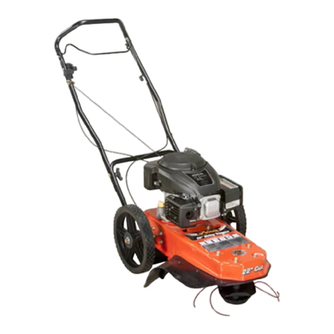
Ariens 946150 - ST622 CARB Owner's manual

Owner/Operator Manual
Models
946501 - ST622
946301 - ST622
String Trimmer
04644401I 9/04
Supersedes 04644401, A-H
Printed in USA
ENGLIS
H
FRANÇAI
S
ESPAÑO
L
Transfer
model &
serial number
label from
product
registration
here.
Coller l’autocollant du
modèle et du numéro de
série dans cet encadré.
Transferir aquí la etiqueta
del modelo y número de
serie del registro del
producto.

2
MODEL DECLARATION OF CONFORMITY ISSUED BY THE MANUFACTURER
CERTIFICAT DE CONFORMITÉ DU MODÈLE DÉLIVRÉ PAR LE
FABRICANT
VOM HERSTELLER AUSGESTELLTE MODELL-
ÜBEREINSTIMMUNGSERKLÄRUNG
MODELCERTIFICAAT VAN OVEREENSTEMMING AFGEGEVEN DOOR DE
FABRIKANT
DICHIARAZIONE DI CONFORMITÀ DEL PRODOTTO REALIZZATA DAL
PRODUTTORE
MODELO DE DECLARACIÓN DE CONFORMIDAD EMITIDA POR EL
FABRICANTE
MODEL KONFORMITETSERKLÆRING UDSTEDT AF FABRIKANTEN
MODELLENS SAMSVARSERKLÆRING UTFERDIGET AV PRODUSENTEN
FÖRSÄKRAN OM MODELLÖVERENSSTÄMMELSE, UTFÄRDAT AV TILLVERKAREN
We the undersigned, - Je soussigné, - Mit meiner Unterschrift - Wij de ondergetekenden, - Il
sottoscritto, - El abajo firmante - Undertegnede, - Undertecknaren av detta dokument, - Me,
allekirjoittaneet.
ARIENS COMPANY, certify that the String Trimmer - certifie que la tondeuse à fil - bescheinigt, daß
der Kantentrimmer - Certifica que la recortadora - certifica che il rifinitore - attesterer, at
strengtrimmeren - bekrefter at gresstrimmeren - försäkrar att kanttrimmaren:
conform to the specifications of directive 2000/14/EC, 98/37/EC, 89/336/EEC and their current
amendments.
est conforme aux spécifications des directives 2000/14/CE, 98/37/CE et 89/336/CEE et à leurs
modifications actuelles.
den Spezifikationen der Richtlinie 2000/14/EC, 98/37/EC, 89/336/EEC und deren aktuellen Zusätzen
entspricht.
voldoet aan de specificaties van richtlijn 2000/14/EG, 98/37/EG, 89/336/EEG en recente aanvullingen
hierop.
è conforme alle specifiche contenute nelle direttive 2000/14/EC, 98/37/EC, 89/336/EEC e nei loro
relativi amendamenti.
cumple las especificaciones de la normativa 2000/14/EC, 98/37/EC, 89/336/EEC y sus enmiendas en
curso.
opfylder specifikationerne i Direktiv 2000/14/EF, 98/37/EF, 89/336/EØF og gældende ændringer.
er i overensstemmelse med spesifikasjonene i direktiv 2000/14/EF, 98/37/EF, 89/336/EØF og de
gjeldende endringer.
överensstämmer med specifikationerna i direktiven 2000/14/EC, 98/37/EC, 89/336/EEC och deras
nuvarande tillägg.
Category: STRING TRIMMER (NONMETALIC LINE WITH KINETIC ENERGY LESS
THAN 10 JOULES)
Make and Trade Name: ARIENS
Model: 946301
Serial # Range: 1405 and up
Cutting Width (cm): 55.9
Representative Measured Sound Power
Level
Niveau de puissance acoustique
représentatif
Repräsentativer gemessener
Geräuschpegel
Typisch gemeten geluidssterkteniveau
Livello di potenza sonora rappresentativo
rilevato
Nivel de potencia acústica representativo
medido
Repræsentativt målt lydstyrkeniveau
Representativt målt lydeffektnivå
Representativ uppmätt ljudnivå
107 dBa
Guaranteed Sound Power Level
Niveau garanti de puissance acoustique
Garantierter Geräuschpegel
Gegarandeerd geluidssterkteniveau
Livello di potenza sonora garantito
Nivel de potencia acústica garantizado
Garanteret lydstyrkeniveau
Garantert lydeffektnivå
Garanterad ljudnivå
109 dBa
A
riens Company
6
55 West Ryan Street
P
.O. Box 157
B
rillion, Wisconsin 54110-0157
U
SA
T
elephone (920) 756-2141
F
acsimile (920) 756-2407

3
Stated Sound Power Levels are established following Annex V “Internal Control of Production” of
directive 2000/14/EC.
Les déclarations de niveau de puissance acoustique sont établies conformément à l'Article V
« Contrôle interne de la production » de la directive 2000/14/CE.
Die angegebenen Geräuschpegel wurden gem. Anhang V „Internal Control of Production“
(Interne Produktionskontrolle) der Richtlinie 2000/14/EC.
Il livello della potenza sonora dichiarata viene rilevato in base all'Appendice V del "Controllo
Interno di Produzione" della direttiva 2000/14/CE .
Los niveles de potencia acústica formulados se establecen siguiendo el anexo V "Control interno
de producción" de la directiva 2000/14/EC.
Lydeffektnivåene er fastsatt etter tillegg V om "Intern produksjonskontroll" i direktiv 2000/14/EC.
Fastställda ljudnivåer har etablerats enligt bilaga V, "Internal Control of Production", i direktiv
2000/14/EC.
Mainitut äänen painetasot on mitattu direktiiviä 2000/14/EC vastaavasti ("Internal Control of
Production")
.
Keeper of Technical File-
Dépositaire du fichier technique - Verwalter der
technischen Dokumente - Houder technische
gegevens - Depositario del file tecnico -
Depositario del archivo técnico - Ansvarlig for
teknisk data - Ansvarlig for teknisk
dokumentasjon - Innehavare of teknisk fil -
Tim Peter
Product Team Leader
Chef d’équipe de produit - Produktteam-Leiter -
Teamleider Product - Capo team produttivo - Jefe del
equipo del producto - Produktansvarlig - Produktansvarlig
- Produktledare
Ariens Company
Signature/
Unterschrift/
Handtekening/
Firma/
Underskrift/
Underskrift
Handlekening/
Underskrift/
Allekirjoitus
4/15/2003
Date/Datum/
Data/Fecha/
Dato/Päiväys
Philip Smucker
Manager of Product Conformance/Position/Qualité/Functie/Qualifica/
Puesto/Stilling/Titel/Arvo
Ariens Company
The engine exhaust from this product
contains chemicals known to the State
of California to cause cancer, birth
defects or other reproductive harm.
WARNING

GB - 4
Safety . . . . . . . . . . . . . . . . . . . . . . . . . . . 5
Assembly . . . . . . . . . . . . . . . . . . . . . . . . 9
Controls and Features . . . . . . . . . . . . 10
Operation . . . . . . . . . . . . . . . . . . . . . . . 11
Maintenance . . . . . . . . . . . . . . . . . . . . 12
Service and Adjustments . . . . . . . . . . 14
Troubleshooting . . . . . . . . . . . . . . . . . 17
Storage . . . . . . . . . . . . . . . . . . . . . . . . . 18
Service Parts . . . . . . . . . . . . . . . . . . . . 18
Specifications . . . . . . . . . . . . . . . . . . . 18
Warranty . . . . . . . . . . . . . . . . . . . . . . . . 19
THE MANUAL
Before operation of unit, carefully and
completely read your manuals. The contents
will provide you with an understanding of
safety instructions and controls during normal
operation and maintenance.
All reference to left, right, front, or rear are
given from operator standing in operation
position and facing the direction of forward
travel.
MODEL AND SERIAL NUMBERS
When ordering replacement parts or making
service inquiries, know the Model and Serial
numbers of your unit and engine.
Numbers are located on the product
registration form in the unit literature package.
They are printed on a serial number label,
located on the frame of your unit.
• Record Engine Model and Serial numbers
here.
PRODUCT REGISTRATION
The Ariens dealer must register the product at
the time of purchase. Registering the product
will help the company process warranty claims
or contact you with the latest service
information. All claims meeting requirements
during the limited warranty period will be
honored, whether or not the product
registration card is returned. Keep a proof of
purchase if you do not register your unit.
Customer Note: If the Dealer does not
register your product, please fill out, sign and
return the product registration card to Ariens
or go to www.ariens.com on the internet.
UNAUTHORIZED REPLACEMENT
PARTS
Use only Ariens replacement parts. Replacing
any part on this vehicle with anything other
than an Ariens authorized replacement part
may adversely affect the performance,
durability, or safety of this unit and may void
the warranty. Ariens disclaims liability for any
claims or damages, whether warranty,
property damage, personal injury or death
arising out of the use of unauthorized
replacement parts. To locate your nearest
Ariens Dealer, call 1-920-756-4664 or go to
www.ariens.com on the internet.
DELIVERY
Customer Note: If you have purchased this
product without complete assembly and
instruction by your retailer, it is your
responsibility to:
• Read and understand all assembly
instructions in this manual. If you do not
understand or have difficulty following the
instructions, contact your nearest Ariens
Dealer for assistance. To locate your
nearest Ariens Dealer, go to
www.ariens.com on the internet or call
1-920-756-4664.
TABLE OF CONTENTS
INTRODUCTION
OX0240
Serial
Number
Label
CE Decal
(946301)
© Copyright 2004 Ariens Company

GB - 5
• Do not operate the unit unless all controls
function as described in this manual.
Before attempting to operate your
unit:
1. Make sure all assembly has been
properly completed.
2. Understand all Safety Precautions
provided in the manuals.
3. Review control functions and operation of
the unit.
4. Review recommended lubrications,
maintenance and adjustments.
5. Review Limited Warranty Policy.
6. Fill out Original Purchaser Registration
Card and return the card to Ariens
Company.
DISCLAIMER
Ariens reserves the right to discontinue,
change, and improve its products at any time
without notice or obligation to the purchaser.
The descriptions and specifications contained
in this manual were in effect at printing.
Equipment described within this manual may
be optional. Some illustrations may not be
applicable to your unit.
SAFETY ALERTS
Look for these symbols to point
out important safety precautions.
They mean:
Attention!
Personal Safety Is Involved!
Become Alert!
Obey The Message!
The safety alert symbols above and signal
words below are used on decals and in this
manual.
Read and understand all safety messages.
NOTATIONS
NOTE: General reference information for
proper operation and maintenance practices.
IMPORTANT: Specific procedures or
information required to prevent damage to unit
or attachment.
PRACTICES AND LAWS
Practice usual and customary safe working
precautions, for the benefit of yourself and
others. Understand and follow all safety
messages. Be alert to unsafe conditions and
the possibility of minor, moderate, or serious
injury or death. Learn applicable rules and
laws in your area.
REQUIRED OPERATOR TRAINING
If unit is to be used by someone other than
original purchaser; loaned, rented or sold,
ALWAYS provide this manual and any needed
safety training before operation.
SAFETY DECALS AND
LOCATIONS
ALWAYS replace missing or damaged Safety
Decals. Refer to figure below for Safety Decal
locations.
WARNING: Improper assembly or
adjustments can cause serious
injury.
SAFETY
DANGER: IMMINENTLY
HAZARDOUS SITUATION! If
not avoided, WILL RESULT in
death or serious injury.
WARNING: POTENTIALLY
HAZARDOUS SITUATION! If not
avoided, COULD RESULT in death
or serious injury.
CAUTION: POTENTIALLY
HAZARDOUS SITUATION! If not
avoided, MAY RESULT in minor or
moderate injury. It may also be
used to alert against unsafe
practices.

GB - 6
1. DANGER! TO AVOID SERIOUS
INJURY OR DEATH
SAFETY RULES
If unit is to be used by someone other than
original purchaser; loaned, rented or sold,
ALWAYS provide this manual and any needed
safety training before operation.
Read, understand and follow all safety
practices in Owner/Operator Manual before
beginning assembly. Failure to follow
instructions could result in personal injury and/
or damage to unit.
ALWAYS disconnect wire from spark plug
before assembly. Unintentional engine start up
can cause death or serious injury.
Complete a walk around inspection of unit and
work area to understand:
• work area
• your unit
• all safety decals.
Clear work area of stones, sticks, wire and
foreign objects which might be picked up and
thrown. Tall grass can hide obstacles.
Know the work area. Stay alert for holes,
rocks, rough terrain and hidden hazards.
Keep away from drop-offs, ditches, or
embankments that could cause operator to
lose footing or control of unit.
ALWAYS be aware of traffic when operating
along streets or curbs.
Keep work area clear of all persons, children
and pets.
Keep children out of the work area and under
the watchful care of a responsible adult.
ALWAYS operate unit when there is good
visibility and light.
Do not operate trimmer in wet grass.
ALWAYS be sure of your footing. Keep a firm
hold on handlebar. Walk, NEVER run.
Read the Operator’s Manual.
Always wear protective
glasses, goggles or a face
shield.
Always wear adequate
hearing protection.
Do not operate when
children or others are
around.
Remove objects that could
be thrown by the cutter line.
Keep body parts away from
rotating cutter line.
1
OX0114
OL180
1
OL4740
OL437
0
OL0910
OL462
0
Go across slopes, not up and
down.
• Keep safety devices (guards,
shields, switches, etc.) in place and
working.
• Look down and behind before and
while moving backwards.
• Do not let debris accumulate.
Debris could become a fire hazard
or cause engine to overheat.
OL461
0

GB - 7
Whenever operator releases control on
handlebar, trimmer head must stop. Check this
feature frequently. If feature fails to operate,
disconnect spark plug wire and adjust or have
it repaired before using unit.
Only trained adults may operate unit. Training
includes actual operation.
NEVER operate after or during the use of
medication, drugs or alcohol. Unit requires
complete and unimpaired attention.
NEVER allow children to operate trimmer.
ALWAYS keep hands and feet away from
rotating parts. Rotating parts can cut off body
parts.
ALWAYS keep hands away from pinch points.
Fumes from engine exhaust can cause death
or serious injury. DO NOT run engine in an
enclosed area.
ALWAYS protect eyes, face, and body with
adequate safety gear and protective clothes.
Wear sturdy footwear, gloves and safety
goggles or safety glasses with side shields
while operating mower.
NEVER operate trimmer barefoot or when
wearing open sandals or canvas shoes.
NEVER wear loose clothes, long hair or
jewelry that may get caught in rotating parts.
Protect eyes, face and head from objects that
may be thrown from unit.
ALWAYS stand clear of discharge when
operating unit.
NEVER direct discharge toward bystanders.
Operator is responsible for bystander safety.
DO NOT touch hot parts. Allow parts to cool.
Keep safety devices or guards in place and
functioning properly. NEVER modify or remove
safety devices.
Read, understand, and follow all instructions in
the manual and on the machine before
starting. Understand:
• How to operate all controls
• The functions of all controls
• How to STOP in an emergency.
DO NOT attempt to start your engine until you
know what the controls do and how they work.
DO NOT tilt trimmer when starting it.
Keep feet away when starting engine.
DO NOT operate trimmer unless trimmer
shield and trailing shield are installed. Objects
may be picked up and thrown causing damage
or personal injury.
NEVER use wire or wire-rope in place of the
cutting line. It can break off and become a
dangerous projectile. Use only flexible, non-
metallic line recommended by Ariens.
ALWAYS keep trimmer head in contact with
the ground while operating.
Take all possible precautions when leaving
unit unattended.
ALWAYS shut off engine and disconnect spark
plug wire to prevent accidental starting or
unauthorized use.
Stop engine if anyone enters the work area.
NEVER attempt to make any adjustments to
unit while engine is running (except where
specifically recommended). Stop engine,
disconnect spark plug wire and wait for all
moving parts to stop before servicing.
DO NOT make cutting height adjustments
while the engine is running.
If you strike an object, or if equipment vibrates
abnormally, stop engine at once, wait for
moving parts to stop and disconnect wire from
spark plug. Repair any damage before
restarting unit.
ALWAYS shut off engine, allow trimmer head
to stop and disconnect spark plug wire before
clearing clogs or cleaning unit.
DO NOT transport machine while engine is
running.
To reduce fire hazard and overheating, keep
equipment free of grass, leaves, debris or
excessive lubricants.
Use extra care when approaching blind
corners, shrubs, trees, or other objects which
may obscure vision.
DO NOT trim at too fast a rate. DO NOT
change engine governor setting or over-speed
the engine.
Do not operate trimmer on gravel or on loose
material such as sand. Stop trimmer when
crossing gravel drives, walks, or roads to
prevent damage or injury from thrown objects.
DO NOT pull trimmer backwards unless
absolutely necessary. Look down and back,
especially for small children, before and while
moving backwards.
DO NOT operate on steep slopes.
NEVER leave unit unattended on a slope.
Chock wheels if parking on a slope.
Trim across the face of slopes, never up and
down. Be especially cautious when changing
direction on slopes.

GB - 8
This product is equipped with an internal
combustion engine. DO NOT use on or near
any unimproved, forest or brush covered land
unless the exhaust system is equipped with a
spark arrestor meeting applicable local, state
or federal laws. A spark arrestor, if used, must
be maintained in effective working order by the
operator. See your Ariens Dealer or engine
manufacturer’s service center.
Fuel is highly flammable and its vapors can
explode. ONLY use approved fuel containers.
• NO Smoking!
• NO Sparks!
• NO Flames!
• Allow engine to cool before filling fuel
tank.
Never fill containers inside a vehicle or on a
truck or trailer bed with a plastic liner. Always
place containers on the ground away from
your vehicle before filling.
When practical, remove gas-powered
equipment from the truck or trailer and refuel it
on the ground. If this is not possible, then
refuel such equipment on a trailer with a
portable container, rather than from a gasoline
dispenser nozzle.
Keep the nozzle in contact with the rim of the
fuel tank or container opening at all times until
fueling is complete. Do not use a nozzle lock-
open device.
Check fuel supply before starting engine.
DO NOT fill gasoline tank indoors, when
engine is running, or while engine is hot.
Allow engine to cool several minutes before
removing fuel cap.
DO NOT overfill. Allow about 1/4" (6 mm) of
tank space for fuel expansion.
Replace gasoline tank cap securely and clean
any spilled fuel before starting engine.
If fuel is spilled on clothing, change clothing
immediately.
NEVER store fuel inside where there is an
open flame, such as a water heater.
ALWAYS drain fuel outdoors away from
ignition sources.
Avoid Electric Shock. DO NOT disconnect
wire from spark plug while engine is running.
Accidental engine start up can cause death or
serious injury. Except where specifically
recommended, ALWAYS stop engine, wait for
moving parts to stop, allow parts to cool and
disconnect spark plug wire before inspecting,
servicing, adjusting or repairing unit.
Keep unit free of grass, leaves, or other debris
build-up.
Keep equipment in good condition.
Maintain or replace safety and instruction
labels, as necessary.
Follow engine manufacturer’s safety
instructions when servicing engine.
Check all hardware at regular intervals,
especially trimmer head attachment bolts.
Keep all hardware properly tightened.
Before tipping unit, remove fuel.
DO NOT tip the trimmer up or over unless
specifically instructed to do so.
Ensure all wheel blocks, jack stands and tie
downs will support unit during maintenance.
Replace worn-out mufflers immediately.
Continued use could result in fire or explosion.
Sharp edges can cut or amputate fingers or a
hand. Wrap blade or wear sturdy gloves to
service.
Use only replacement parts designed for your
unit. See your Ariens Dealer.
Allow engine to cool before storing in any
enclosure.
ALWAYS clean unit before extended storage.
See engine manual for proper storage.
DO NOT store unit inside a building with fuel in
the fuel tank where any ignition sources are
present.
Use only accessories which have been
approved by Ariens and are properly installed.
Check attachments frequently and replace
worn or damaged components with
manufacturer’s recommended parts.

GB - 9
TOOLS REQUIRED
• Box knife to cut carton
TO REMOVE UNIT FROM CARTON
1. Cut off top of box.
2. Remove packing material.
3. Remove literature pack, safety glasses
and bottle of oil from box.
4. Cut out back of box and pull the unit out.
5. Remove protective packaging materials
from trimming head and around unit.
ASSEMBLY
Handlebar Assembly
1. Loosen handlebar wing knobs. Do not
remove them.
2. Unfold handlebar to operating position.
NOTE: Adjust handlebar to a height
comfortable for the operator. Be sure cable is
clear of pinch points. Refer to Handlebars in
Service and Adjustments.
3. Tighten handlebar wing knobs to secure
upper handlebar.
Engine Crankcase Oil
Fill engine crankcase with proper amount and
viscosity of oil. Refer to Engine Manual for
specific information.
CHECKLIST
Please complete the following checklist before
proceeding:
• All assembly instructions have been
completed.
• No remaining loose parts in carton.
• Handlebar is adjusted comfortably and
tightened securely.
While learning how to use your unit,
pay extra attention to the following
important items:
• Trimming line is fastened securely in
holder.
• Fuel tank is filled with proper fuel.
• Engine crankcase is filled with oil.
• Become familiar with all controls – their
location and function. Operate them
before you start the engine.
ASSEMBLY
WARNING: AVOID INJURY. Read
and understand the entire Safety
section before proceeding.
1. Lower Handle
Bar
2. Upper Handle
Bar
3. Carriage Bolt
4. Wing Knobs
5. Bolt Holes
6. Control Bail
OX0013
4
3
1
6
2
5
4

GB - 10
1. Trimmer Head
2. Trimmer Line
3. Upper Handlebar
4. Lower Handlebar
5. Control Bail
6. Throttle Control Lever
7. Recoil Starter Handle
8. Handlebar Wing Knob
9. Oil Dipstick and Cap
10.Fuel Tank and Cap
11.Debris Screen
12.Air Cleaner
13.Primer Bulb
14.Swivel Head Lock
15.Trimmer Shield
16.Trailing Shield
CONTROLS AND FEATURES
OX0255
OX0250
1
2
3
4
5
6
7
8
9
10
11
12
13
14
15
16
OX0245

GB - 11
CONTROLS AND FEATURES
See Controls and Features on page 10.
Trimmer Head / Trimmer Lines
The trimmer head holds the trimmer line and
provides trimming height adjustment. When
mounted in the trimmer, the trimmer lines
extend about 8 in. (20.3 cm) from the cutter
disk.
Control Bail
• Squeeze the trimmer control bail against
the handlebar to engage trimmer head.
• Release bail to disengage trimmer.
IMPORTANT: Check control bail function
before each use. If control bail moves freely
with no resistance before contacting
handlebar, adjust or repair unit before
operating. See Service and Adjustments.
Throttle Control Lever
The throttle control
lever controls the
speed of the engine.
The settings are
variable between fast
and slow.
Recoil Starter Handle
The recoil starter handle is used to start the
engine.
Primer Bulb
For a cold engine, push the
primer bulb three times to
add fuel for easier engine
start. See Starting and Shut
Off.
Swivel Head Lock
The swivel head feature is designed to allow
close trimming while walking parallel to fences
or walls.
• Point the front of the unit to the left if
trimming with the left side of the trimmer.
• Point the front of the unit to the right if
trimming with the right side of the trimmer.
To adjust, see Service and Adjustments.
FILLING FUEL TANK
To add fuel to Fuel Tank:
1. Put unit in open or well-ventilated area.
2. Stop engine and allow to cool.
3. Clean Fuel Cap and surrounding area to
prevent dust, dirt and debris from entering
Fuel Tank.
4. Remove Cap.
IMPORTANT: DO NOT use gasohol or
gasoline containing alcohol because alcohol
will cause internal parts to deteriorate. See
Engine Manual for correct type and grade of
fuel.
5. Fill fuel tank. (See Specifications for tank
capacity.)
6. Replace Fuel Cap and tighten.
7. ALWAYS clean up any spilled fuel.
TO STOP IN AN EMERGENCY
To stop in an emergency, release control bail.
When all moving parts have stopped, push
throttle control lever to stop.
TO START AND SHUT OFF
ENGINE
Pre-Start
1. Check engine oil level. See Engine
Manual.
2. Check fuel level.
Starting the Engine
1. Push primer bulb 2 or 3 times for a cold
engine.
2. Set throttle control to Fast.
OPERATION
WARNING: AVOID INJURY. Read
and understand the entire Safety
section before proceeding.
OX0210
Fast Slow Stop
3 x
OX0040
WARNING: EXPLOSIVE VAPORS
and FLAMMABLE FUEL can
result in serious injury or death.
Handle fuel with care. ALWAYS
use an approved fuel container.
No Smoking! No Lighted Materials!
No Open Flame!
Allow engine to cool before
maintenance.
Never fill tank when engine is
running or is hot from operation.
DO NOT overfill tank. Allow about
1/4" (6.35 mm ) of space at the top
of the filler neck for fuel expansion.
Wipe up any spills and allow
vapors to dissipate before starting
engine. Use approved (Red)
gasoline container.

GB - 12
3. Grasp starter handle and pull rope out
slowly until it pulls harder. This is the
compression stroke. Let rope rewind
slowly. Then pull rope with rapid
continuous full arm stroke to start engine.
Allow rope to rewind slowly.
IMPORTANT: DO NOT let starter handle snap
against handlebar.
4. Repeat until engine starts. (If engine does
not start, refer to Troubleshooting.)
Stopping the Engine
1. Release control bail so that trimmer head
stops rotation. Wait until rotating parts
stop completely before leaving operator’s
position.
2. Push throttle control lever to Stop.
3. If leaving unit unattended, disconnect
spark plug wire to prevent start-up.
TO OPERATE THE TRIMMER
1. Start the engine.
2. Set throttle control to Fast.
3. Hold the control bail against the
handlebar to engage the trimmer head.
4. When trimmer head is rotating at full
speed, move unit forward to trim.
TO TRAVEL TO ANOTHER WORK
AREA
When crossing driveways or bare areas,
release the control bail to stop trimmer head
rotation and push down slightly on the
handlebar to lift the trimmer head off the
ground. This prevents premature wear of the
trimmer head.
TRIMMING TIPS
• Operating the trimmer in Fast throttle
provides the best trimming performance.
• In heavy growth, walk slower.
• Do not push the trimmer into heavy
growth too fast.
• Do not trim on extremely steep slopes. Do
not trim on slopes when the ground is wet
or slippery. If you do not feel comfortable
on a slope, do not trim it.
• Keep the trimmer clear of dirt and grass
build-up.
• Install a new trimmer line when line is
worn to less than 4 inches (10.2 cm). See
Service and Adjustments.
TO TRANSPORT UNIT
ALWAYS turn engine off when transporting on
truck or trailer. Tie unit down securely. Do not
tie down by linkages, guards, cables or other
parts that may be damaged.
SERVICE POSITION
1. Remove the gas cap and place a piece of
plastic (a plastic garbage bag works well)
over the tank opening. Reinstall the cap.
This keeps gasoline from spilling out the
tank.
2. Set the unit swivel in the center position.
3. Loosen the two wing nuts on the lower
handlebar.
4. Tip the unit up onto its back to rest on the
lower handlebar. A 4" x 4" (10.2 x
10.2 cm) wood block under the swivel
bracket helps steady the unit by tilting it
farther back.
5. When service is complete, place unit in its
normal operating position.
6. Align handlebars and tighten wing nuts.
CAUTION: Before every use,
clean grass and debris from foam
debris screen and around muffler.
MAINTENANCE
WARNING: AVOID INJURY. Read
and understand the entire Safety
section before proceeding.
Maintenance Schedule
Service Performed Intervals (Hours)
Each
Use 25 50
Check Fasteners •
Check Trimmer Lines •
Check Control Bail
Operation •
Check Engine Oil •
Clean Debris Screen •
Clean Unit •
Check Air Cleaner •1
Check Spark Plug •
Change Engine Oil •2 •1
Clean Engine Cooling Fins •1
1. More often under extremely dusty or dirty
conditions.
2. Change engine oil after first 2 hours of
use, then every 25 hours or every
season, whichever comes first.
Maintenance Schedule

GB - 13
7. Be sure to remove the plastic from the
gas tank opening.
CHECK FASTENERS
Make sure all hardware is tightened properly.
Pay special attention to handlebar, guards,
shields, and trimmer head mounting hardware.
CHECK TRIMMER LINES
Make sure trimmer line is securely fastened in
holder. Replace trimmer line when it is worn to
less than 4 inches (10.2 cm) . See Service and
Adjustments for specific instructions.
CHECK CONTROL BAIL
OPERATION
The trimmer head must disengage completely
when the bail handle is released. Adjust bail
travel if necessary. See Adjustments.
CHECK ENGINE OIL
See Engine Manual for specific information on
checking engine oil.
CLEAN DEBRIS SCREEN
Remove all grass and debris from debris
screen on top of engine. A clogged screen will
cause the engine to overheat.
CLEAN UNIT
Clean unit thoroughly. Brush dirt and debris off
with a brush or cloth. Apply paint or spray
lubricant to exposed metal surfaces. Do not
use abrasives, solvents, or harsh cleaners.
IMPORTANT: NEVER spray unit with water or
store unit outdoors. Store trimmer in a cool,
dry, protected location.
CHECK AIR CLEANER
See Engine Manual for specific information on
checking and servicing the air cleaner.
CHECK SPARK PLUG
See Engine Manual for specific information on
checking, cleaning, and changing the spark
plug.
CHANGE ENGINE OIL
Change the engine oil after the first 2 hours of
use, then every 25 hours or every season,
whichever comes first. Oil should be changed
when engine is warm.
1. Disconnect spark plug wire.
2. Clean area around oil cap.
3. Tip the string trimmer on its right side.
4. Place a container for the oil under the oil
cap.
5. Remove oil cap and let the oil drain. Tip
the unit more to drain all the oil from the
engine if necessary.
6. Place the unit upright.
7. Refill the engine with oil recommended in
the Engine Manual.
8. Replace and tighten oil cap.
9. Clean up any spilled oil.
10.Reconnect the spark plug wire.
CLEAN ENGINE COOLING FINS
Remove grass, dirt and debris from engine
cooling fins every 25 hours to prevent damage
caused by overheating.
Wood Block
OX0260
CAUTION: Before tipping unit,
remove enough fuel so no spillage
will occur. A piece of plastic bag
may be used to seal fuel tank when
tipping unit. To seal, remove fuel
tank cap, cover fuel tank opening
with plastic, replace and tighten
cap securely before attempting to
tip unit. Be sure to remove plastic
before operating unit.

GB - 14
REPLACING TRIMMER LINE
Replace the trimmer line when it extends less
than 4 inches (10.2 cm) from cutter disk. For
best results, use only genuine Ariens
replacement trimmer line.
1. Stop the engine and wait for all moving
parts to stop. Disconnect the spark plug
wire and place it securely away from the
spark plug.
2. Remove the worn trimmer line from the
cutter disk.
3. Thread the two ends of the trimmer line
up from the bottom, through the two holes
in the cutter disk.
4. Cross the line and thread the ends of the
line through the two holes on the side of
the cutter disk.
5. Make sure the ends of the line extend
through the cutter disk at the same length.
Uneven trimmer lines cause the trimmer
head to be out of balance, which results in
excessive vibration.
6. Pull trimmer line tight.
7. If necessary, cut the ends of the trimmer
line to the same length.
HANDLEBAR HEIGHT
ADJUSTMENT
1. Loosen and remove both wing knobs from
handlebar.
2. Remove carriage bolts, taking care to
support handlebar.
3. Set handlebar to desired height.
4. Line up holes in upper handlebar with
holes in lower handlebar. Be sure to use
the same holes on each side.
5. Reinstall carriage bolts and wing knobs.
Tighten securely.
CUTTING HEIGHT ADJUSTMENT
The standard cutting height is adjustable from
1-3/16" to 4-3/8" (3 to 11.1 cm). To raise the
cutting height, place more spacers (up to 4)
below the cutter disk. Spacers not used under
the cutter disk must be assembled above the
cutter disk. For example, if you place two
spacers under the cutter disk, the other two
spacers must be in place above the cutter
disk.
NOTE: There must always be at least one
spacer between the cutter disk and the height
guide.
1. Raise the cutter head off the ground.
2. Loosen and remove capscrew, lock
washer and washer.
SERVICE AND ADJUSTMENTS
WARNING: AVOID INJURY. Read
and understand the entire Safety
section before proceeding.
OX0063
OX008
0
1. Hex Shaft
2. Spacers
3. Cutter Disk
4. Height Guide
5. Washer
6. Lock Washer
7. Cap Screw
2
5
1
3
4
6
7
1 spacer = 1-3/16"
(3 cm)
2 spacers = 2-3/4"
(7 cm)
3 spacers = 3-5/8"
(9.2 cm)
4 spacers = 4-3/8"
(11.1 cm)
OX0090
2

GB - 15
3. Remove height guide and bottom spacer.
4. Remove cutter disk and any of the
remaining spacers required to achieve the
desired cutting height.
5. Reinstall the cutter disk.
6. Reinstall the spacers required to achieve
the desired cutting height.
7. Reinstall height guide on the hex shaft.
NOTE: Be sure the hex shaft and the hex hole
in the height guide are correctly aligned.
8. Reinstall washer, lock washer and
capscrew. Tighten securely.
NOTE: The minimum cutting height may be
lowered to 1-3/16" (3 cm) by using one spacer
below the cutter disk and installing the cutter
disk upside down on the hex shaft.
HEIGHT GUIDE REPLACEMENT
The height guide requires periodic
replacement. When used on hard surfaces,
such as concrete, it may need to be replaced
more frequently. If height guide is damaged or
worn, it must be replaced.
1. Raise the cutter head off the ground.
2. Loosen and remove capscrew, lock
washer and washer.
3. Remove worn height guide.
4. Install new height guide.
5. Reinstall hardware and tighten securely.
SWIVEL HEAD ADJUSTMENT
1. Stop the engine and wait for all moving
parts to stop. Disconnect the spark plug
wire and place it securely away from the
spark plug.
2. Loosen the wing knob on the bracket at
the rear of the unit.
3. Rotate the back of the unit in the opposite
direction of the side you wish to cut with.
4. Tighten wing knob securely.
CONTROL BAIL TRAVEL
ADJUSTMENT
Control Bail must disengage trimmer head as
control is released. There should be a slight
amount of slack in the control cable wire when
bail is fully released. If the trimmer head does
not disengage completely when the control
bail is released, increase the amount of slack
in the control cable wire as follows:
1. Loosen the bottom cable nut.
2. Push the cable conduit upward toward the
control bail.
3. Tighten the upper cable nut onto the
mounting bracket to lock the conduit in
place.
4. Turn nuts against mount to lock in
position.
Wing Knob OX0070
1. Control Cable
2. Control Cable
Wire
3. Control Bail
4. Handlebar
5. Cable Nuts
6. Cable Conduit
24
51
OX0120
3
6

GB - 16
DRIVE BELT REPLACEMENT
To remove the old belt:
1. Stop the engine and wait for all moving
parts to stop. Disconnect the spark plug
wire and place it securely away from the
spark plug.
2. Place unit in service position (see
Maintenance section).
3. Remove the six (6) hex washer head
screws and the trimmer shield.
4. Remove the four (4) hex washer head
screws on the top side of the frame. The
jackshaft assembly, belt fingers and
jackshaft spacers will now be loose.
5. Remove the v-belt from the jackshaft
pulley.
6. Remove the capscrew and lock washer
from the engine sheave.
1. Six hex washer
head screws
2. Trimmer shield
3. Four hex
washer head
screws
4. Trimmer frame
5. Jackshaft
assembly
6. Jackshaft
spacers
7. Jackshaft
pulley belt
fingers
8. V-belt
9. Jackshaft
pulley
10.Engine sheave
11.Capscrew
12.Lock washer
13.Engine sheave
belt fingers
OX0020
1
2
3
7
8
9
4
5
6
10
11
12
13
1
1
CAUTION: Before tipping unit,
remove enough fuel so no spillage
will occur. A piece of plastic bag
may be used to seal fuel tank when
tipping unit. To seal, remove fuel
tank cap, cover fuel tank opening
with plastic, replace and tighten
cap securely before attempting to
tip unit. Be sure to remove plastic
before operating unit.
43
2
1
7
6
5
1. Engine sheave
belt fingers
2. Engine sheave
3. Idler
4. Idler belt finger
5. V-belt
6. Jackshaft
pulley belt
fingers
7. Jackshaft
pulley
OX0100

GB - 17
7. Lower the engine sheave past the belt
fingers and remove the belt.
To install the new belt:
1. Slide the new belt over the groove in the
engine sheave and slide the sheave
against the engine. Make sure the belt is
in the groove and is inside the belt fingers.
2. Install the capscrew and lock washer.
Tighten securely.
3. Slide the belt between the idler and belt
finger on the idler bracket.
4. Install the four tapping screws in the holes
in the frame, from the top side of the
frame.
5. Install the four jackshaft spacers on the
tapping screws.
6. Install the belt finger. Make sure the bent
tabs are facing up and are to the sides
and front of the unit.
7. Install the belt in the groove of the
jackshaft pulley.
8. Attach the jackshaft assembly to the
frame with the four tapping screws.
Fasten securely.
9. Reinstall the trimmer shield with the six
tapping screws.
TROUBLESHOOTING
PROBLEM PROBABLE CAUSE CORRECTION
Engine will
not start or
runs poorly
1. Spark plug wire disconnected.
2. Engine not primed
3. Fuel tank empty.
4. Throttle control lever not in
correct position.
5. Engine is flooded.
6. Defective or incorrectly gapped
spark plug.
7. Stale or contaminated gasoline.
8. Engine cooling system
overloaded with debris.
9. Dirty carburetor or fuel line.
10.Dirty air filter or precleaner.
11.Carburetor out of adjustment.
1. Connect spark plug wire.
2. Prime engine.
3. Add fuel to the fuel tank.
4. See Engine Manual.
5. Wait several minutes before
attempting to start.
6. Replace or regap spark plug.
7. Drain fuel tank and refill with
fresh gasoline.
8. Clean debris screen and
cooling fins.
9. Clean carburetor or fuel line.
See Engine Manual.
10.Replace air filter or
precleaner.
11.See Engine Manual or
contact your dealer.
Engine
overheats
1. Engine cooling system
overloaded with debris.
2. Carburetor out of adjustment.
1. Clean engine screen and
cooling fins.
2. See Engine Manual or
contact your dealer.
Poor
trimming
performance
1. Engine not set at Fast speed. 1. Set engine throttle to Fast
position.
Trimmer
vibrates
1. Cutter line lengths are too
uneven.
2. Loose hardware.
1. Trim or adjust cutter line to
equal lengths. Replace if
necessary.
2. Check all bolts and nuts,
including engine mounting
hardware, for tightness.

GB - 18
If the trimmer is to be stored for more than 30
days, follow these steps to prepare your unit.
1. Run the engine until it stops from running
out of gasoline. See Engine Manual for
specific instructions on preparing the
engine for storage.
2. Clean all dirt and debris from the trimmer.
Refer to Maintenance for cleaning
instructions.
3. Inspect unit for signs of wear, breakage or
damage. Order any parts required and
make necessary repairs to avoid delays
when beginning use again.
4. Keep all nuts, bolts and screws properly
tightened and know unit is in safe working
condition.
STORAGE
WARNING: AVOID INJURY. Read
and understand the entire Safety
section before proceeding.
SERVICE PARTS
Be sure to always use genuine Ariens parts
to keep your String Trimmer running like
new.
Part no. Qty Description
07236900 1 Drive Belt
04641800 1 Trimmer Line (Pkg of 6)
04641100 1 Height Guide
04645000 1 Long Life Height Guide
SPECIFICATIONS
Model Number 946501 946301
Description ST622
Engine Tecumseh
LEV120-361076C
Engine Power - HP
(KW) 6 (4.48)
Engine Operating Fast
Idle Speed - Max. RPM 3750
Engine Displacement
- cu. in. (cc)
12.06 (197.6)
Fuel See Engine
Manual for type
and grade
Fuel Tank Capacity - qt
(Liters) 1.25 (1.18)
Cutting Width - in (cm) 22 (55.88)
Handlebars Max.
Extended Height - in
(cm)
41.38 (105.11)
Minimum Folded Height
- in (cm) 19.38 (49.23)
Length - in (cm) 57.88 (147.02)
Minimum Folded
Length - in (cm) 37.25 (94.62)
Width - in (cm) 22 (55.88)
Weight - lbs (Kg) 83 (37.65)
Cutter Head Speed -
Max. RPM 3650
Drive Belt 4L Section,
Single “V”
Construction,
Raw Edge Kevlar
Cord
Wheel Size - in (cm) 14
(35.56) 14
(35.56)
Replacement Line
Length - in. (cm)
Diameter - in. (cm)
18 (46)
5/32 (0.40)
CE Sound and Vibration (946301)
Oper. Ear Sound Press. (Lpa) dBA93
VIBRATION MEASURE (m /s2) @ Operator
hands
X axis <2.5
Y axis 2.6
Z axis 3.7

GB - 19

Ariens Company
655 West Ryan Street
P.O. Box 157
Brillion, WI 54110-0157
920-756-2141
Fax 920-756-2407
www.ariens.com
Other manuals for 946150 - ST622 CARB
1
This manual suits for next models
2
Table of contents
Other Ariens Trimmer manuals

Ariens
Ariens String Trimmer User manual

Ariens
Ariens 946500 User manual

Ariens
Ariens 946152 User manual

Ariens
Ariens 946101-ST622 Owner's manual

Ariens
Ariens 90102800 User manual

Ariens
Ariens 946150 - ST622 CARB Owner's manual

Ariens
Ariens 946154 User manual

Ariens
Ariens 000101 Owner's manual

Ariens
Ariens 9602032 User manual