Ariens 946500 User manual


1
Section 1 - Introduction . . . . . . . . . . . . . . . . . 1-2
1.1 The Manual . . . . . . . . . . . . . . . . . . . . . . . 1-2
1.2 Service and Replacement Parts . . . . . . . 1-2
1.3 Product Registration . . . . . . . . . . . . . . . . 1-2
1.4 Unauthorized Replacement Parts . . . . . . 1-2
1.5 Disclaimer . . . . . . . . . . . . . . . . . . . . . . . . 1-2
1.6 Technical Service Communications. . . . . 1-2
Section 2 - Safety
2.1 Safety Alerts . . . . . . . . . . . . . . . . . . . . . . 2-3
2.2 Notations . . . . . . . . . . . . . . . . . . . . . . . . . 2-3
2.3 Practices and Laws . . . . . . . . . . . . . . . . . 2-3
2.4 Required Operator Training. . . . . . . . . . . 2-3
2.5 Storage . . . . . . . . . . . . . . . . . . . . . . . . . . 2-3
2.6 Safety Rules . . . . . . . . . . . . . . . . . . . . . . 2-3
Section 3 - Specifications . . . . . . . . . . . . . . . 3-5
Section 4 - General Maintenance
& Adjustments . . . . . . . . . . . . . . . . . . . . . . 4-6
4.1 Controls And Features. . . . . . . . . . . . . . . 4-6
4.2 Filling Fuel Tank. . . . . . . . . . . . . . . . . . . . 4-7
4.3 To Stop In An Emergency . . . . . . . . . . . . 4-7
4.4 Replacing Trimmer Line. . . . . . . . . . . . . . 4-7
4.5 Handlebar Height Adjustment . . . . . . . . . 4-7
4.6 Cutting Height Adjustment. . . . . . . . . . . . 4-7
4.7 Control Bail Travel Adjustment . . . . . . . . 4-8
Section 5 - Engine. . . . . . . . . . . . . . . . . . . . . . 5-9
5.1 Engine Troubleshooting. . . . . . . . . . . . . . 5-9
5.2 Check Engine Oil. . . . . . . . . . . . . . . . . . .5-10
5.3 Check Air Cleaner . . . . . . . . . . . . . . . . . .5-10
5.4 Check Spark Plug . . . . . . . . . . . . . . . . . .5-10
5.5 Change Engine Oil. . . . . . . . . . . . . . . . . .5-10
Section 6 - Drive Belt Replacement. . . . . . . .6-11
Section 7 - Jackshaft Housing Replacement7-13
TABLE OF CONTENTS

2
1.1 THE MANUAL
Before operation of unit, carefully and completely read
your manuals. The contents will provide you with an
understanding of safety instructions and controls
during normal operation and maintenance.
All reference to left, right, front, or rear are given from
the operation position, facing the direction of forward
travel.
1.2 SERVICE AND REPLACEMENT PARTS
When ordering replacement parts or making service
inquiries, know the Model and Serial numbers of your
unit and engine.
Numbers are located on the product registration form in
the unit literature package. They are also printed on a
serial number label, located on the frame of your unit
(Figure 1).
1.3 PRODUCT REGISTRATION
A warranty registration card must be filled out by the
Ariens dealer, signed, and returned at time of sale. This
card activates the warranty. Claims meeting
requirements during limited warranty period will be
honored.
1.4 UNAUTHORIZED REPLACEMENT
PARTS
Use only Ariens replacement parts. The replacement of
any part on this vehicle with anything other than an
Ariens authorized replacement part may adversely
affect the performance, durability, or safety of this unit
and may void the warranty. Ariens disclaims liability for
any claims or damages, whether warranty, property
damage, personal injury, or death arising out of the use
of unauthorized replacement parts.
1.5 DISCLAIMER
Ariens reserves the right to discontinue, make changes
to, and add improvements upon its products at any
time without public notice or obligation. The
descriptions and specifications contained in this
manual were in effect at printing. Equipment described
within this manual may be optional. Some illustrations
may not be applicable to your unit.
1.6 TECHNICAL SERVICE
COMMUNICATIONS
Ariens Technical Service communicates information to
the field using Service Letters, Service Bulletins,
Product Notices, and Campaigns. Each
communication signifies a type of information and
priority. The dealer is responsible to carry out the
directive provided in the communication. The types of
communication are:
Service Letter - General technical information for the
dealer. Technical information on how to service the
product and product improvements.
Service Bulletin - Notification to update products to
resolve certain issues or a notification of a policy
change.
Product Notices - Notification of limited product
located in a certain region. This is a limited distribution
to only those who received the product involved.
Campaigns - Notification of a safety related issue. All
product must be updated and are tracked by the
factory until all units are corrected.
SECTION 1 - INTRODUCTION
Figure 1 OX0070
Serial Number

2 - 3
2.1 SAFETY ALERTS
Look for these symbols to point out
important safety precautions. They
mean:
Attention!
Personal Safety Is Involved!
Become Alert!
Obey The Message!
The safety alert symbol is used in decals on the unit
and with proper operation procedures in this manual.
Understand the safety message. It contains important
information about personal safety on or near the unit.
2.2 NOTATIONS
NOTE: General reference information for proper oper-
ation and maintenance practices.
IMPORTANT: Specific procedures or information
required to prevent damage to unit or attachment.
2.3 PRACTICES AND LAWS
Practice usual and customary safe working
precautions, for the benefit of yourself and others.
Understand and follow all safety messages. Be alert to
unsafe conditions and the possibility of minor,
moderate, or serious injury or death. Learn applicable
rules and laws in your area.
2.4 REQUIRED OPERATOR TRAINING
If unit is to be used by someone other than original
purchaser; loaned, rented or sold, ALWAYS provide
this manual and any needed safety training before
operation.
2.5 STORAGE
If the trimmer is to be stored for more than 30 days,
follow these steps to prepare your unit.
1. Run the engine until it stops from running out of
gasoline. See Engine Manual for specific
instructions on preparing the engine for storage.
2. Clean all dirt and debris from the trimmer.
3. Inspect unit for signs of wear, breakage or
damage. Order any parts required and make
necessary repairs to avoid delays when beginning
use again.
4. Keep all nuts, bolts and screws properly tightened
and know unit is in safe working condition.
2.6 SAFETY RULES
Preparation
Inspect unit and work area before operation. Clear
work area of objects which might be picked up and
thrown. Remove all stones, sticks, wires, and other
foreign objects. Tall grass can hide obstacles.
Only Trained adults may operate unit. Training includes
actual operation.
Keep equipment in good condition.
Wear adequate safety gear, long sleeve shirts, long
pants and protective gloves.
Wear sturdy footwear. DO NOT operate trimmer when
barefoot or when wearing open sandals or canvas
shoes.
Always wear eye protection when operating trimmer.
NEVER wear loose clothing, jewelry or long hair that
may get caught in rotating parts. Protect eyes, face and
head from objects that may be thrown from unit.
Fuel is highly flammable and its vapors can explode.
ONLY use approved fuel containers.
• NO Smoking!
• NO Sparks!
• NO Flames!
• Allow engine to cool before filling fuel tank.
Check fuel supply before starting engine.
SECTION 2 - SAFETY
DANGER: IMMINENTLY HAZARDOUS
SITUATION! If not avoided, WILL RESULT in
death or serious injury.
WARNING: POTENTIALLY HAZARDOUS
SITUATION! If not avoided, COULD RESULT
in death or serious injury.
CAUTION: POTENTIALLY HAZARDOUS
SITUATION! If not avoided, MAY RESULT in
minor or moderate injury. It may also be used
to alert against unsafe practices.
WARNING: FLAMMABLE FUEL and its
EXPLOSIVE VAPORS can cause death or
serious injury. DO NOT store unit inside a
building with fuel in the fuel tank where any
ignition sources are present. Drain fuel
outdoors away from any ignition source. Allow
engine to cool before storing in any enclosure.
Only use approved fuel containers.

2 - 4
DO NOT fill gasoline tank indoors, when engine is
running, or while engine is still hot.
Allow engine to cool several minutes before removing
fuel cap.
Replace gasoline tank cap securely and clean up any
spilled fuel before starting engine.
Operation
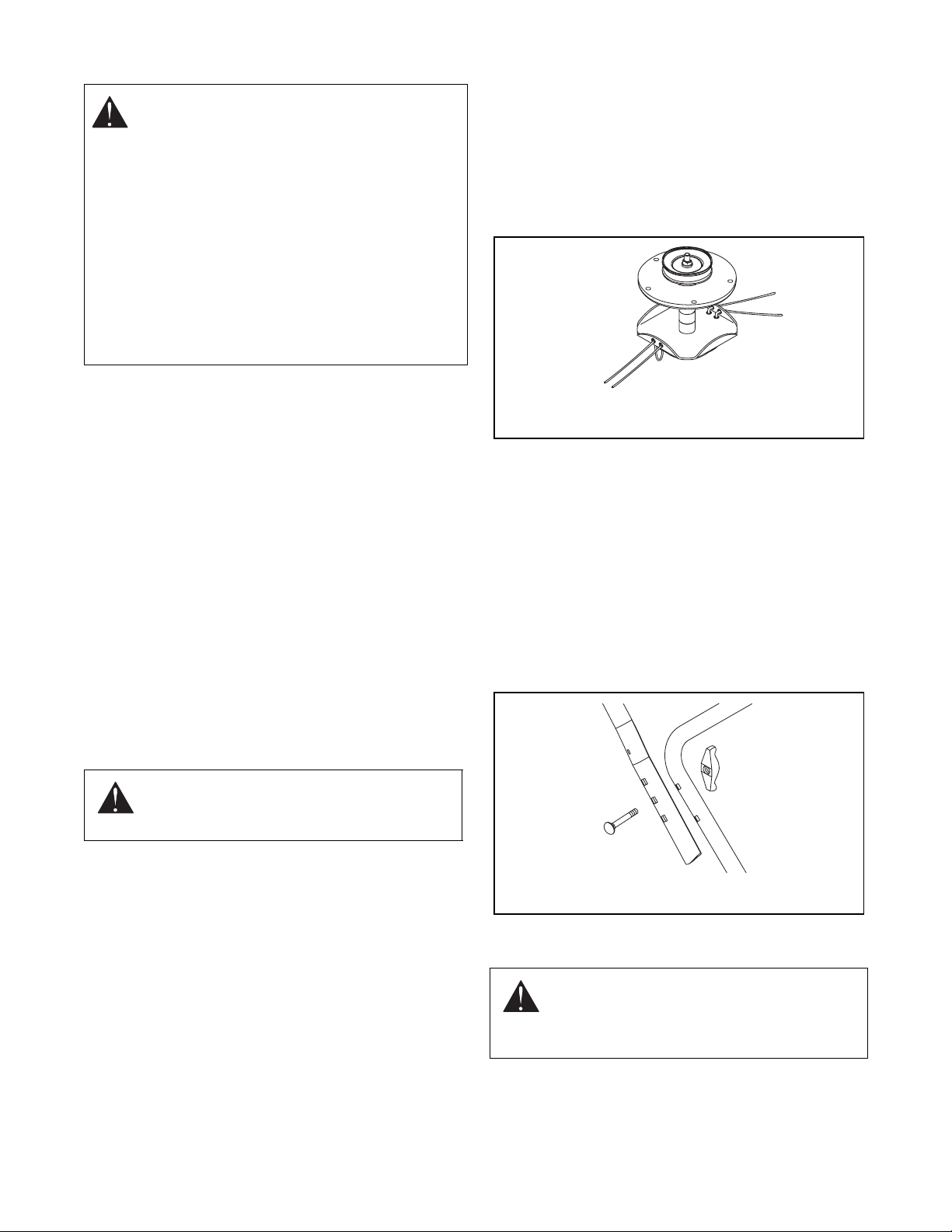
NEVER use wire or wire-rope in place of the cutting
line. It can break off and become a dangerous
projectile. Use only flexible, non-metallic line
recommended by Ariens .
DO NOT pull trimmer backwards unless absolutely
necessary. Look down and back before and while
moving backwards. Keep a firm footing.
ALWAYS keep trimmer head in contact with the ground
while operating.
Keep the area of operation clear of all persons,
children and pets.
Stop trimmer if anyone enters the area.
Keep safety devices or guards in place and functioning
properly. NEVER modify or remove safety devices.
ALWAYS keep discharge cover in place.
ALWAYS keep hands and feet away from all rotating
parts during operation.
DO NOT trim at too fast a rate. DO NOT change
engine governor setting or over-speed the engine.
ALWAYS operate unit when there is good visibility and
light.
Use extra care when approaching blind corners,
shrubs, trees, or other objects which may obscure
vision.
Do not operate trimmer in wet grass. Always be sure of
your footing. Keep a firm hold on handlebar. Walk,
never run.
If equipment vibrates abnormally, stop engine
immediately, wait for moving parts to stop and remove
wire from spark plug. Repair any damage before
restarting unit.
Avoid uneven work areas and any rough terrain.
Be familiar with area of operation. Stay alert for holes
rocks, roots, and hidden hazards in area of operation.
Keep away from drop-offs, ditches or embankments.
Operator could lose footing or balance.
DO NOT operate on steep slopes. If you feel
uncomfortable on a slope, do not trim it.
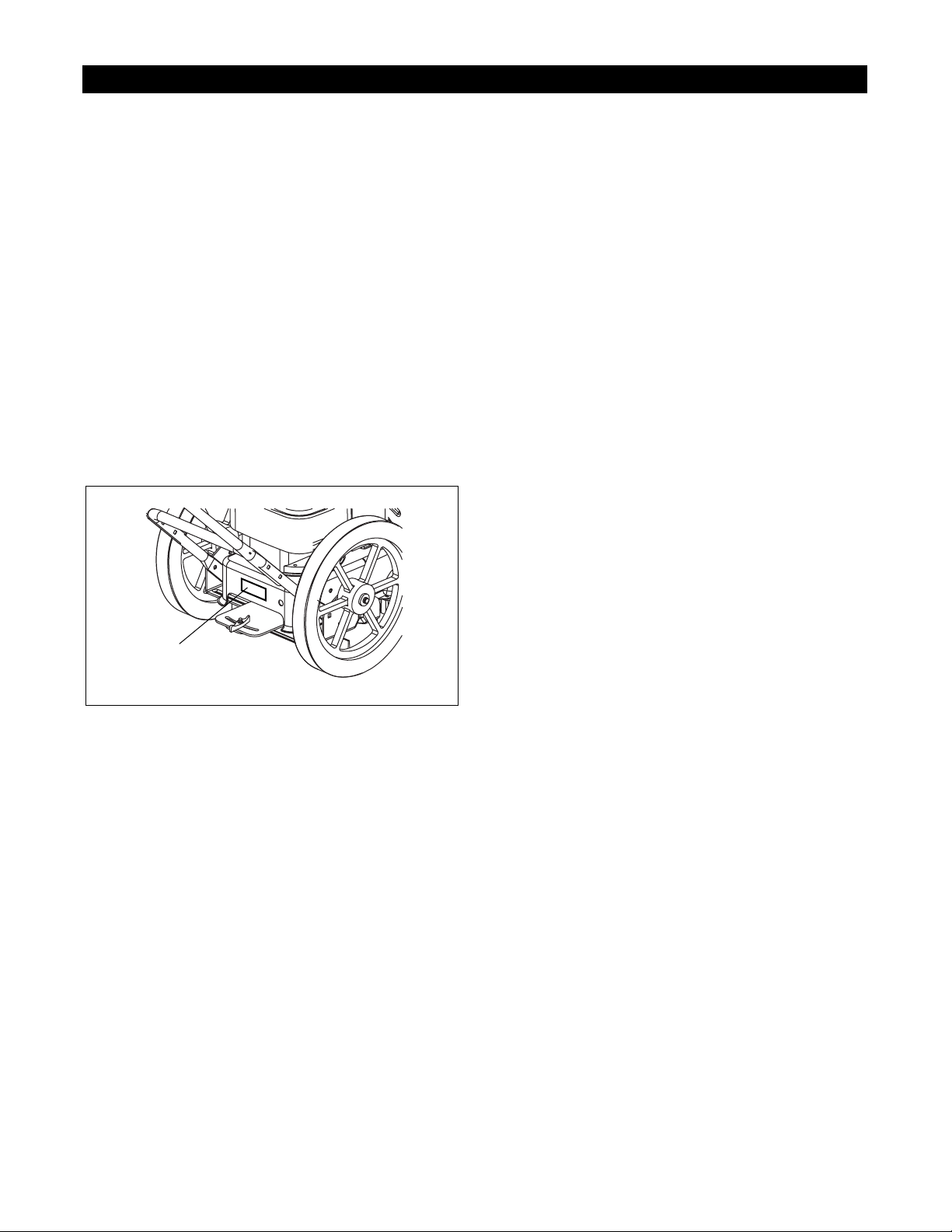
NEVER leave unit unattended on a slope. Chock
wheels if parking on a slope.
Trim across the face of slopes, never up and down. Be
especially cautious when changing direction on slopes.
Take all possible precautions when leaving unit
unattended. Shut off engine. Remove wire from spark
plug and secure it away from spark plug.
Personal
Keep children out of work area and under the watchful
care of an adult.
NEVER allow children to operate trimmer.
Turn the trimmer off if children enter the area.
NEVER direct discharge toward bystanders. The
operator is responsible for the safety of bystanders.
NEVER operate after or during the use of medication,
drugs or alcohol. Complete and unimpaired attention is
required when operating unit.
ALWAYS stand clear of discharge when operating unit.
Do not operate trimmer on gravel or on loose material
such as sand. Stop trimmer when crossing gravel
drives, walks, or roads. Objects may be picked up and
thrown, causing damage or injury.
DO NOT touch parts which are hot. Allow parts to cool.
Moving parts can cut or amputate fingers or a hand.
Fumes from the engine exhaust can cause death or
serious injury. DO NOT run engine in an enclosed
area.
Maintenance, Service and Storage
Stop engine, wait for moving parts to stop, remove
ignition wire and secure away from spark plug before
attempting to repair, adjust, inspect or clean unit.
Follow engine manufacturer’s safety instructions when
servicing engine.
Keep all nuts, bolts, and screws tight and be sure
equipment is in safe working condition. Check all
hardware at regular intervals, especially engine and
trimmer head attachment bolts.
Use only replacement parts designed for your unit. See
your Ariens Dealer.
Worn out mufflers are more than just a noise nuisance
and should be replaced immediately. Continued use
could result in fire or explosion.
Check components for wear, damage, and/or
deterioration. Replace only with Ariens original
equipment replacement parts.
DO NOT tip the trimmer up or over unless specifically
instructed to do so.
DO NOT make cutting height adjustments while the
engine is running.
To reduce fire hazard and overheating, keep
equipment free of grass, leaves, debris or excessive
lubricants.
Allow engine to cool before storing in any enclosure.
Refer to Storage for important instructions if unit is to
be stored for extended periods.
ALWAYS clean unit before extended storage. See
engine manual for proper storage.
DO NOT store unit with fuel in the fuel tank inside a
building where any ignition sources are present.

3 - 5
Safety Interlock System
Whenever operator releases control on handlebar,
trimmer head must stop. If feature fails to operate,
disconnect spark plug wire and adjust or have it
repaired before using unit.
Replacement Parts and Accessories
Use only replacement parts and accessories which
have been approved by Ariens and are properly
installed.
Spark Arrestor
This product is equipped with an internal combustion
engine. DO NOT use on or near any unimproved,
forest or brush covered land unless the exhaust system
is equipped with a spark arrestor meeting applicable
local, state or federal laws. A spark arrestor, if used,
must be maintained in effective working order by the
operator. See your Ariens Dealer or engine
manufacturer’s service center.
SECTION 3 - SPECIFICATIONS
Model Number 946500 946501
Description Name ST522 ST622
Engine Power - HP (KW) 5 (3.73) 6 (4.48)
Engine Operating Fast Idle Speed
- RPM 3600 3600
Engine Displacement - cu. in. (cc) 12.06 (197.6) 12.06 (197.6)
Fuel See Engine Manual
for type and grade See Engine Manual
for type and grade
Fuel Tank Capacity - qt (L) 1.25 (1.18) 1.25 (1.18)
Cutting Width - in (cm) 22 (55.88) 22 (55.88)
Handlebars Max. Extended Height
- in (cm) 41.38 (105.11) 41.38 (105.11)
Length - in (cm) 57.88 (147.02) 57.88 (147.02)
Minimum Folded Length - in (cm) 37.25 (94.62) 37.25 (94.62)
Width - in (cm) 22 (55.88) 22 (55.88)
Weight - lbs (kg) 83 (37.65) 83 (37.65)
Cutter Head Speed - RPM 3600 3600
Drive Belt 4L Section, Single
"V" Construction,
Raw Edge Kevlar
Cord
4L Section, Single
"V" Construction,
Raw Edge Kevlar
Cord
Wheel Size - in (cm) 14 (35.56) 16 (40.64)

4 - 6
4.1 CONTROLS AND FEATURES
SECTION 4 - GENERAL MAINTENANCE & ADJUSTMENTS
OX0200
1. Trimmer Head
2. Trimmer Line
3. Debris Shield
4. Upper Handlebar
5. Lower Handlebar
6. Control Bail
7. Throttle Control Lever
8. Recoil Starter Handle
9. Handlebar Wing Knob
10.Oil Dipstick and Cap
11.Fuel Tank and Cap
12.Debris Screen
13.Air Cleaner
14.Primer Bulb
15.Swivel Head Lock
16.Trimmer Shield
17.Trailing Shield
Figure 2
1
2
3
45
6
7
8
9
10
11 12
13
14
15
16
17

4 - 7
4.2 FILLING FUEL TANK
To add fuel to fuel tank:
1. Put unit in open or well-ventilated area.
2. Stop engine and allow to cool.
3. Clean fuel cap and surrounding area to prevent
dust, dirt and debris from entering fuel tank.
4. Remove cap.
IMPORTANT: DO NOT use gasohol or gasoline
containing alcohol because alcohol will cause internal
parts to deteriorate. See Engine Manual for correct
type and grade of fuel.
5. Fill fuel tank. (See Specifications for tank capacity.)
6. Replace fuel cap and tighten.
7. ALWAYS clean up any spilled fuel.
4.3 TO STOP IN AN EMERGENCY
To stop in an emergency, release control bail. When all
moving parts have stopped, push throttle control lever
to stop.
4.4 REPLACING TRIMMER LINE
Replace the trimmer line when it is less than 4 inches
(10.1 cm) long. For best results, use only genuine
Ariens replacement trimmer line.
1. Stop the engine and wait for all moving parts to
stop. Disconnect the spark plug wire and place it
securely away from the spark plug.
2. Remove the worn trimmer line from the cutter disk.
3. Thread the two ends of the trimmer line up from the
bottom, through the two holes in the cutter disk.
4. Thread the ends of the line through the two holes
on the side of the cutter disk.
5. Make sure the ends of both lines extend through
the cutter disk at the same length on both sides of
the cutter disk. Uneven trimmer lines cause the
trimmer head to be out of balance, which results in
excessive vibration.
6. Pull trimmer line tight.
7. If necessary, cut the ends of the trimmer line to the
same length.
4.5 HANDLEBAR HEIGHT ADJUSTMENT
1. Loosen and remove both wing knobs from
handlebar.
2. Remove carriage bolts, taking care to support
handlebar.
3. Set handlebar to desired height.
4. Line up holes in upper handlebar with holes in
lower handlebar. Be sure to use the same holes on
each side.
5. Reinstall carriage bolts and wing knobs. Tighten
securely.
4.6 CUTTING HEIGHT ADJUSTMENT
The standard cutting height is adjustable from 2" to
4-3/8" (5 to 11.11 cm). To raise the cutting height, place
more spacers (up to 4) below the cutter disk. Spacers
not used under the cutter disk must be assembled
WARNING: EXPLOSIVE VAPORS and
FLAMMABLE FUEL can result in death or
serious injury. Handle fuel with care.
ALWAYS use an approved fuel container.
No Smoking! No lighted Materials!
No Open Flame!
Allow engine to cool before maintenance.
Never fill tank when engine is running or is hot
from operation. DO NOT overfill tank. Allow
about 1/4" of space at the top of the filler neck
for fuel expansion. Wipe up any spills and
allow vapors to dissipate before starting
engine. Use approved gasoline container.
CAUTION: ALWAYS shut off unit and
disconnect spark plug wire before servicing
or making any adjustments.
CAUTION: ALWAYS shut off unit,
disconnect spark plug wire and allow hot
parts to cool before making any cutting
height adjustments.
OX0060
Figure 3
OX0080
Figure 4

4 - 8
above the cutter disk. For example, if you place two
spacers under the cutter disk, the other two spacers
must be in place above the cutter disk.
NOTE: There must always be at least one spacer
between the cutter disk and the height guide.
1. Raise the cutter head off the ground.
2. Loosen and remove capscrew, lock washer and
washer.
3. Remove height guide and bottom spacer.
4. Remove cutter disk and any of the remaining
spacers required to achieve the desired cutting
height.
5. Reinstall the cutter disk.
6. Reinstall the spacers required to achieve the
desired cutting height.
7. Reinstall height guide on the hex shaft.
NOTE: Be sure the hex shaft and the hex hole in the
height guide are correctly aligned.
8. Reinstall washer, lock washer and capscrew.
Tighten securely.
NOTE: The minimum cutting height may be lowered to
1-3/16" by using one spacer below the cutter disk and
installing the cutter disk upside down on the hex shaft.
4.7 CONTROL BAIL TRAVEL
ADJUSTMENT
Control bail must disengage trimmer head as control is
released. There should be a slight amount of slack in
the control cable wire when bail is fully released. If the
trimmer head does not disengage completely when the
control bail is released, increase the amount of slack in
the control cable wire as follows:
1. Loosen the bottom cable nut.
2. Push the cable conduit upward toward the control
bail.
3. Tighten the upper cable nut onto the mounting
bracket to lock the conduit in place.
4. Turn nuts against mount to lock in position.
OX0090
Figure 5
1. Hex Shaft
2. Spacers
3. Cutter Disc
4. Height Guide
5. Washer
6. Lock Washer
7. Cap Screw
1 spacer = 2"
2 spacers = 2-3/4"
3 spacers = 3-5/8"
4 spacers = 4-3/8"
1
2
3
4
5
6
7
OX0120
Figure 6
1. Control Cable
2. Control Cable Wire
3. Control Ball
4. Handlebar
5. Cable Nuts
6. Cable Conduit

5 - 9
5.1 ENGINE TROUBLESHOOTING
The following troubleshooting chart is to be used to
isolate engine problems and give possible causes and
corrective action responses.
The trouble shooting key is generic and can be used
for several types of engines. Use only those possible
causes and corrective actions that apply to the unit.
SECTION 5 - ENGINE
TROUBLE POSSIBLE CAUSES
(Refer to Key Below) CORRECTIVE ACTION
Black Exhaust 1, 20, 22, 25, 29, 31, 32, 33 repair or replace
Blue/White Exhaust 4, 20, 25, 31, 33, 34 repair or replace
Difficult Starting 1, 5, 7, 8, 9, 10, 20, 21, 22, 29, 31, 32, 33 repair or replace
Erratic Running 1, 7, 8, 9, 10, 20, 21, 23, 26, 29, 33, 59, 62 repair or replace
Excessive Fuel Consumption 1, 20, 22, 23, 25, 29, 31, 32, 33 repair or replace
Excessive Crankcase Pressure 25, 31, 33, 34, 45, 55 repair or replace
High Oil Pressure 4, 41 repair or replace
Knocking 22, 26, 29, 31, 33, 36, 46, 59 repair or replace
Loss of Power or System 1, 8, 10, 20, 21, 22, 23, 25, 26, 31, 32, 33 repair or replace
Low Cranking Power 2, 3, 4, 11 repair or replace
Low Oil Pressure 4, 36, 37, 39 repair or replace
Misfiring 10, 20, 25, 26, 28, 29, 32 repair or replace
Overheating 1, 19, 25 repair or replace
Poor Compression 25, 28, 29, 31, 32, 33, 34, 59 repair or replace
Starts and Stops 1, 6, 10, 62 repair or replace
see electrical systems
see engine service manual
Vibration 20, 23, 25, 26, 29, 33, 45, 49 repair or replace
Will Not Crank 2, 11, 45 charge battery or replace
Will Not Start 1, 10, 62 repair or replace
see electrical systems
see engine service manual
TROUBLESHOOTING KEY
1 Restriction in air cleaner 22 Incorrect grade of fuel 43 Faulty suction pipe
2 Bad electrical connection 23 Sticking throttle/restricted movement 44 Choked oil filter
3 Faulty starter motor 24 Exhaust pipe restriction 45 Bad solenoid switch
4 Incorrect grade of lubricating oil 25 Leaking cylinder head gasket 46 Incorrect piston height
5 Low cranking speed 26 Overheating 47 Damaged fan
6 Fuel tank empty 27 Cold running 48 Faulty engine mounting
7 Controls not in correct operation
position 28 Incorrect tappet adjustment 49 Incorrectly aligned flywheel and/or flywheel
housing
8 Blocked fuel feed line 29 Sticking valves 50 Faulty thermostat
9 Faulty fuel lift pump 30 Incorrect high pressure pipes 51 Restriction in water jacket
10 Choked fuel filter 31 Worn cylinder bores 52 Loose fan belt
11 Battery capacity low 32 Pitted valves and seats 53 Choked radiator
12 Air in fuel system 33 Broken, worn or sticking piston
ring(s) 54 Faulty water pump
13 Faulty fuel injection pump 34 Worn valve stems and guides 55 Choked breather pipe
14 Faulty fuel injectors or incorrect
type 35 Over full air cleaner 56 Damaged valve stem oil deflector (if fitted)
15 Incorrect use of cold start
equipment 36 Worn or damaged bearings 57 Coolant level too low
16 Faulty cold start equipment 37 Insufficient oil in sump 58 Blocked sump strainer
17 Broken fuel injection pump drive 38 Bad/defective oil temperature switch 59 Broken valve spring
18 Incorrect fuel pump timing 39 Oil pump worn 60 Exhaust or vacuum pipe leak
19 Incorrect valve timing 40 Pressure relief valve sticking open 61 Bad or defective water temperature switch
20 Poor compression 41 Pressure relief valve sticking closed 62 Bad spark plug(s)
21 Blocked fuel tank vent 42 Broken relief valve spring

5 - 10
5.2 CHECK ENGINE OIL
See Engine Manual for specific information on
checking engine oil.
5.3 CHECK AIR CLEANER
See Engine Manual for specific information on
checking and servicing the air cleaner.
5.4 CHECK SPARK PLUG
See Engine Manual for specific information on
checking, cleaning, and changing the spark plug.
5.5 CHANGE ENGINE OIL
Change the engine oil after the first 2 hours of use,
then every 25 hours or every season, whichever comes
first. Oil should be changed when engine is warm.
1. Disconnect spark plug wire.
2. Clean area around oil cap.
3. Tip the string trimmer on its right side.
4. Place a container for the oil under the oil cap.
5. Remove oil cap and let the oil drain. Tip the unit
more to drain all the oil from the engine if
necessary.
6. Place the unit upright.
7. Refill the engine with oil recommended in the
Engine Manual.
8. Replace and tighten oil cap.
9. Clean up any spilled oil.
10.Reconnect the spark plug wire.
CAUTION: Before tipping unit, remove
enough fuel so no spillage will occur. A piece
of plastic bag may be used to seal fuel tank
when tipping unit. To seal, remove fuel tank
cap, cover fuel tank opening with plastic,
replace and tighten cap securely before
attempting to tip unit. Be sure to remove
plastic before operating unit.

6 - 11
To remove the old belt:
1. Stop the engine and wait for all moving parts to
stop. Disconnect the spark plug wire and place it
securely away from the spark plug.
2. Remove the trimmer shield.
3. Remove the gas cap and place a piece of plastic (a
plastic garbage bag works well) over the tank
opening. Reinstall the cap. This keeps gasoline
from spilling out of the tank.
4. Set the unit swivel in the center position.
5. Loosen the two wing nuts on the lower handlebar.
6. Tip the unit up onto its back to rest on the lower
handlebar. A 4" x 4" (10 x 10 cm) wood block under
the swivel bracket helps steady the unit by tilting it
farther back.
7. Remove the four (4) washer head screws on the
top side of the frame. The jackshaft assembly, belt
fingers and jackshaft spacers will now be loose.
8. Remove the v-belt from the jackshaft pulley.
9. Remove the capscrew and lock washer from the
engine sheave.
10.Lower the engine sheave past the belt fingers and
remove the belt.
SECTION 6 - DRIVE BELT REPLACEMENT
OX0090
Figure 7
1. Hex Washer Head
Screws
2. Trimmer Shield
3. Washer Head Screws
4. Trimmer Frame
5. Jackshaft Assembly
6. Jackshaft spacers
7. Jackshaft Pulley Belt
Fingers
8. V-belt
9. Jackshaft Pulley
10.Engine Sheave
11.Capscrew
12.Lockwasher
13.Engine Sheave Belt
Fingers
1
2
3
4
5
6
7
8
9
10
11
1
12
13
OX0100
Figure 8
1. Engine Sheave Belt
Fingers
2. Engine Sheave
3. Idler
4. Idler Belt Finger
5. V-Belt
6. Jackshaft Pulley Belt
Fingers
7. Jackshaft Pulley
1
2
3
4
5
67

6 - 12
To install the new belt:
1. Slide the new belt over the groove in the engine
sheave and slide the sheave against the engine.
Make sure the belt is in the groove and is inside the
belt fingers.
2. Install the capscrew and lockwasher. Tighten
securely.
3. Slide the belt between the idler and belt finger on
the idler bracket.
4. Install the four tapping screws in the holes in the
frame, from the top side of the frame. Install the
four jackshaft spacers on the tapping screws.
5. Install the belt finger. Make sure the bent tabs are
facing up and are to the sides and front of the unit.
6. Install the belt in the groove of the jackshaft pulley.
7. Attach the jackshaft assembly to the frame with the
four tapping screws. Fasten securely.
8. Reinstall the trimmer shield with the six tapping
screws.
9. When service is complete, place unit in its normal
operating position.
10.Align handlebars and tighten wing nuts.
11.Be sure to remove the plastic from the gas tank
opening.

7 - 13
1. Stop the engine and wait for all moving parts to
stop. Disconnect the spark plug wire and secure it
away from the spark plug.
2. Remove the trimmer shield.
3. Remove the gas cap and place a piece of plastic (a
plastic garbage bag works well) over the tank
opening. Reinstall the cap. This keeps gasoline
from spilling out of the tank.
4. Set the unit swivel in the center position.
5. Loosen the two wing nuts on the lower handlebar.
6. Tip the unit up onto its back to rest on the lower
handlebar. A 4" x 4" (10 x 10 cm) wood block under
the swivel bracket helps steady the unit by tilting it
farther back.
7. Remove the four (4) hex washer head screws on
the top side of the frame. The jackshaft assembly
and belt fingers will now be loose.
8. Remove the v-belt from the jackshaft.
9. Remove the nut from the top of the cutter shaft.
10.Slide the pulley off and remove the shaft from the
housing.
11.Replace the jackshaft housing and assemble in
reverse order.
12.When service is complete, place unit in its normal
operating position.
13.Align handlebars and tighten wing nuts.
14.Be sure to remove the plastic from the gas tank
opening.
SECTION 7 - JACKSHAFT HOUSING REPLACEMENT
PX0020
Figure 9
1. Tension Spring
2. Belt Finger
3. V-Pulley
4. Jackshaft Housing
5. Hex Height Guide
6. Hex Spacer
7. Hex Cutter Disc
8. Hex Cutter Shaft
1
2
3
4
5
6
7
8

Ariens Company
655 West Ryan Street
P.O. Box 157
Brillion, WI 54110-0157
920-756-2141
Fax 920-756-2407
www.ariens.com
This manual suits for next models
3
Table of contents
Other Ariens Trimmer manuals

Ariens
Ariens 946150 - ST622 CARB Owner's manual

Ariens
Ariens 9602032 User manual

Ariens
Ariens 946150 - ST622 CARB Owner's manual

Ariens
Ariens 90102800 User manual

Ariens
Ariens 946154 User manual

Ariens
Ariens 946101-ST622 Owner's manual

Ariens
Ariens 000101 Owner's manual

Ariens
Ariens String Trimmer User manual

Ariens
Ariens 946152 User manual
Popular Trimmer manuals by other brands

Weed Eater
Weed Eater BC2400 instruction manual

Parkside
Parkside PHSL 900 A3 Translation of the original instructions

Troy-Bilt
Troy-Bilt 182826 TB4000 Owner's/operator's manual

Garden Groom
Garden Groom GG01 instruction manual

Stanley
Stanley SXPG42604 operating manual

Ergo tools
Ergo tools Pattfield E-RT 3525 Directions for use