installation &
operating instructions
Design Envelope 4302 ivs and 4382 ivs vertical
in-line pumping unit with integrated controls
5
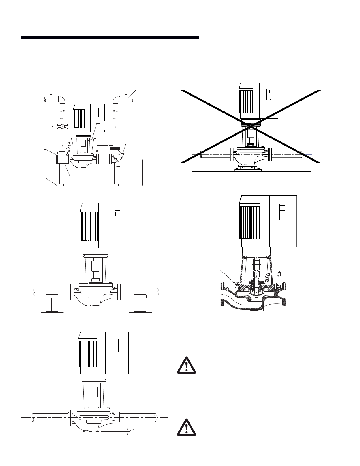
attached either to the plate or to the block. Leave a V" (3mm)
gap between pump and base. The piping must be installed in
such a manner that the pump is not used as a pipe support.
• Do not rigidly connect the pump to a permanent base (See
Fig. 2.7 on page 10) Note: if the pump must be connected to a
permanent base, the pump must be isolated from the piping
by flexible connectors and the base isolated from the building
structure on an inertia base.
• Do not install the unit with the shaft horizontal.
• Do not support the installed unit by the motor eye bolts or
by supports to any other part of the pump other than stated
above.
important
All Series 4302 ivs pumps contain a tapped hole in the motor
bracket above the discharge flange for draining the well. Pipe
this drain hole to a floor drain to avoid overflow of the cavity
caused by collecting chilled water condensate or from seal
failure.
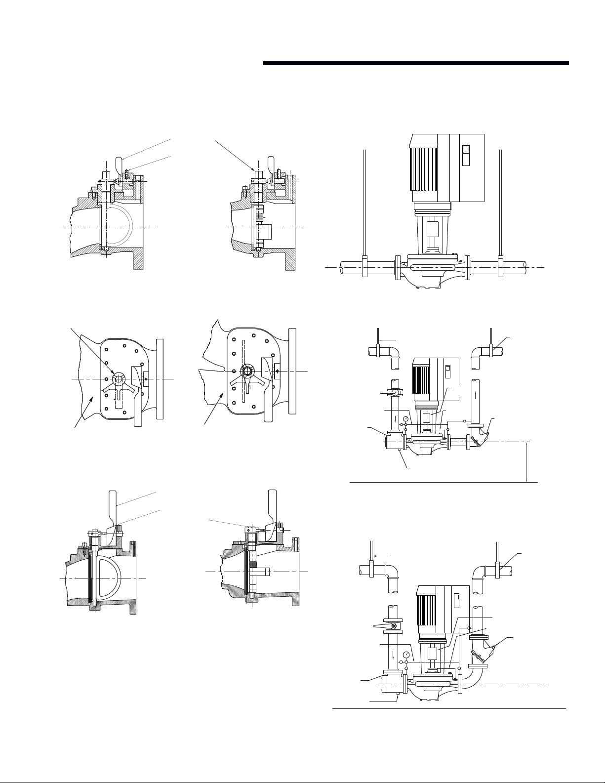
2.1.4 pump piping – general
Never connect a pump to piping, always start piping from
pump.
Use as few bends as possible and preferably long radius el-
bows.
Do not use flexible connectors on the suction or discharge.
Make sure piping exerts no strain on pump as this would distort
the casing and cause pump misalignment.
Suction and discharge pipes may be increased at pump nozzle
to suit pump capacity and particular conditions of installation.
Use eccentric reducers on suction connection.
Lay out the suction line with a continual rise towards the pump
without high points, thus eliminating possibility of air pockets
that may prevent the pump from operating.
A strainer of three or four times the area of the suction pipe,
installed in the suction line, will prevent the entrance of foreign
materials into the pump. V" (3mm) diameter perforations in
the strainer are typical.
Test suction line for air leaks before starting; this becomes
essential with long suction line or static lift.
Install, at pump suction, a straight pipe of a length equivalent to
4or 6 times its diameter; this becomes essential when handling
liquids above 120°f (49°c). Armstrong suction guides may be
used in place of the straight pipe run and in line strainer.
Install isolation valve in both suction and discharge lines on
flooded suction application; this valve is used mainly to isolate
the pump for inspection or repair.
Install a non-slam check valve in discharge line between pump
and isolation valve to protect pump from excessive back pres-
sure and to prevent water running back through the pump in
case of driver failure. Armstrong Flo-Trex valve may be used in
place of check valve and isolation valve on pump discharge.
caution
Discharge valve only must be used to reduce the
pump flow, not the suction valve.
Care must be taken in the suction line layout and
installation, as it is usually the major source of
concern in centrifugal pump applications.
important
Do not run the pump for any length of time under very low flow
conditions or with the discharge valve closed. To do so could
cause the water in the casing to reach super heated steam
conditions and will cause premature failure and could cause se-
rious and dramatic damage to the pump and surrounding area.
2.1.5 alignment
The pumping unit is accurately aligned at the factory prior to
being shipped.
Alignment on the 4302 dualArm may be verified by assuring
an equal gap between coupling halves on both sides of the
coupling.
operation
2.1.6 starting pump
The pump must be fully primed on start up. Fill the pump
casing with liquid and rotate the shaft by hand to remove any
air trapped in the impeller. Air trapped in the casing must be
removed by the manual air vent in the seal flush line. Ensure
entrained air is removed from series 4302 ivs and 4382 ivs
pumps, prior to starting, through the air vent on the seal flush
line. Open vent until clear of air.
“Bump” or energize the motor for a fraction of a second and
check that the rotation corresponds with the directional arrow
on the pump casing.
To reverse rotation of a three phase motor, interchange any two
power leads.